EP4334541B1 - Procédé de fabrication d'un élément composite et élément composite - Google Patents
Procédé de fabrication d'un élément composite et élément composite Download PDFInfo
- Publication number
- EP4334541B1 EP4334541B1 EP21726032.2A EP21726032A EP4334541B1 EP 4334541 B1 EP4334541 B1 EP 4334541B1 EP 21726032 A EP21726032 A EP 21726032A EP 4334541 B1 EP4334541 B1 EP 4334541B1
- Authority
- EP
- European Patent Office
- Prior art keywords
- recess
- reinforcement
- composite element
- composite
- concrete
- Prior art date
- Legal status (The legal status is an assumption and is not a legal conclusion. Google has not performed a legal analysis and makes no representation as to the accuracy of the status listed.)
- Active
Links
Images



Classifications
-
- E—FIXED CONSTRUCTIONS
- E04—BUILDING
- E04B—GENERAL BUILDING CONSTRUCTIONS; WALLS, e.g. PARTITIONS; ROOFS; FLOORS; CEILINGS; INSULATION OR OTHER PROTECTION OF BUILDINGS
- E04B5/00—Floors; Floor construction with regard to insulation; Connections specially adapted therefor
- E04B5/16—Load-carrying floor structures wholly or partly cast or similarly formed in situ
- E04B5/32—Floor structures wholly cast in situ with or without form units or reinforcements
- E04B5/36—Floor structures wholly cast in situ with or without form units or reinforcements with form units as part of the floor
- E04B5/38—Floor structures wholly cast in situ with or without form units or reinforcements with form units as part of the floor with slab-shaped form units acting simultaneously as reinforcement; Form slabs with reinforcements extending laterally outside the element
-
- E—FIXED CONSTRUCTIONS
- E04—BUILDING
- E04B—GENERAL BUILDING CONSTRUCTIONS; WALLS, e.g. PARTITIONS; ROOFS; FLOORS; CEILINGS; INSULATION OR OTHER PROTECTION OF BUILDINGS
- E04B5/00—Floors; Floor construction with regard to insulation; Connections specially adapted therefor
- E04B5/02—Load-carrying floor structures formed substantially of prefabricated units
-
- E—FIXED CONSTRUCTIONS
- E04—BUILDING
- E04B—GENERAL BUILDING CONSTRUCTIONS; WALLS, e.g. PARTITIONS; ROOFS; FLOORS; CEILINGS; INSULATION OR OTHER PROTECTION OF BUILDINGS
- E04B5/00—Floors; Floor construction with regard to insulation; Connections specially adapted therefor
- E04B5/16—Load-carrying floor structures wholly or partly cast or similarly formed in situ
- E04B5/17—Floor structures partly formed in situ
- E04B5/23—Floor structures partly formed in situ with stiffening ribs or other beam-like formations wholly or partly prefabricated
-
- E—FIXED CONSTRUCTIONS
- E04—BUILDING
- E04B—GENERAL BUILDING CONSTRUCTIONS; WALLS, e.g. PARTITIONS; ROOFS; FLOORS; CEILINGS; INSULATION OR OTHER PROTECTION OF BUILDINGS
- E04B5/00—Floors; Floor construction with regard to insulation; Connections specially adapted therefor
- E04B5/16—Load-carrying floor structures wholly or partly cast or similarly formed in situ
- E04B5/17—Floor structures partly formed in situ
- E04B5/23—Floor structures partly formed in situ with stiffening ribs or other beam-like formations wholly or partly prefabricated
- E04B5/26—Floor structures partly formed in situ with stiffening ribs or other beam-like formations wholly or partly prefabricated with filling members between the beams
- E04B5/261—Monolithic filling members
-
- E—FIXED CONSTRUCTIONS
- E04—BUILDING
- E04B—GENERAL BUILDING CONSTRUCTIONS; WALLS, e.g. PARTITIONS; ROOFS; FLOORS; CEILINGS; INSULATION OR OTHER PROTECTION OF BUILDINGS
- E04B5/00—Floors; Floor construction with regard to insulation; Connections specially adapted therefor
- E04B5/48—Special adaptations of floors for incorporating ducts, e.g. for heating or ventilating
-
- E—FIXED CONSTRUCTIONS
- E04—BUILDING
- E04C—STRUCTURAL ELEMENTS; BUILDING MATERIALS
- E04C3/00—Structural elongated elements designed for load-supporting
- E04C3/02—Joists; Girders, trusses, or trusslike structures, e.g. prefabricated; Lintels; Transoms; Braces
- E04C3/29—Joists; Girders, trusses, or trusslike structures, e.g. prefabricated; Lintels; Transoms; Braces built-up from parts of different material, i.e. composite structures
-
- E—FIXED CONSTRUCTIONS
- E04—BUILDING
- E04B—GENERAL BUILDING CONSTRUCTIONS; WALLS, e.g. PARTITIONS; ROOFS; FLOORS; CEILINGS; INSULATION OR OTHER PROTECTION OF BUILDINGS
- E04B5/00—Floors; Floor construction with regard to insulation; Connections specially adapted therefor
- E04B5/16—Load-carrying floor structures wholly or partly cast or similarly formed in situ
- E04B5/17—Floor structures partly formed in situ
- E04B5/23—Floor structures partly formed in situ with stiffening ribs or other beam-like formations wholly or partly prefabricated
- E04B2005/232—Floor structures partly formed in situ with stiffening ribs or other beam-like formations wholly or partly prefabricated with special provisions for connecting wooden stiffening ribs or other wooden beam-like formations to the concrete slab
- E04B2005/235—Wooden stiffening ribs or other wooden beam-like formations having a special form
-
- E—FIXED CONSTRUCTIONS
- E04—BUILDING
- E04B—GENERAL BUILDING CONSTRUCTIONS; WALLS, e.g. PARTITIONS; ROOFS; FLOORS; CEILINGS; INSULATION OR OTHER PROTECTION OF BUILDINGS
- E04B5/00—Floors; Floor construction with regard to insulation; Connections specially adapted therefor
- E04B5/16—Load-carrying floor structures wholly or partly cast or similarly formed in situ
- E04B5/17—Floor structures partly formed in situ
- E04B5/23—Floor structures partly formed in situ with stiffening ribs or other beam-like formations wholly or partly prefabricated
- E04B2005/232—Floor structures partly formed in situ with stiffening ribs or other beam-like formations wholly or partly prefabricated with special provisions for connecting wooden stiffening ribs or other wooden beam-like formations to the concrete slab
- E04B2005/237—Separate connecting elements
Definitions
- the invention relates to a method for producing a composite element.
- the invention relates to a composite element comprising a first element with a recess and at least one second element connected to the first element, which has a hardened material and a reinforcement.
- Such composite elements are used, for example, in the construction of buildings to connect elements made of different materials, for example elements made of wood with elements made of concrete.
- the disadvantage of such composite elements is that they always require concreting on a construction site, which on the one hand means that industrial production such as with a prefabricated house is not possible. On the other hand, concreting on site is also associated with a high level of time and expense.
- FR 2 780 427 A1 discloses a method according to the preamble of claim 1 and a composite element according to the preamble of claim 7.
- the object of the invention is to provide a method of the type mentioned at the beginning, which can be implemented particularly efficiently.
- an efficiently manufactured composite element of the type mentioned above is to be specified which has a high load-bearing capacity.
- the first object is achieved according to the invention by a method according to independent claim 1, in which a first element is provided with a recess, after which a reinforcement partially protruding from the recess is positioned in the recess, after which the recess is filled with hardenable material, in particular concrete, after which the hardenable material hardens in the recess to form a second element, so that the reinforcement is positively connected to the first element via the hardened material.
- a connection between the first element and the second element can also be made in advance, for example in a prefabricated component factory, so that industrial production of the composite element is possible.
- a composite element produced according to the invention thus has a first element with a recess and a second element which has a hardened material and a reinforcement usually made of steel, the first element and the second element being positively connected via the recess.
- the recess is filled with a shrinkage-compensated, hardenable material, particularly shrinkage-compensated concrete. This ensures that the form fit for force transmission is maintained even when the material hardens.
- a first element is provided with a recess, which recess extends essentially along a longitudinal direction and has a cross-section that changes along the longitudinal direction with arrow-shaped shear cams.
- the usually plate-shaped element can then be connected to the reinforcement in a shear-resistant manner along the longitudinal direction by the hardened material.
- the composite element can be used advantageously in particular as a ceiling element, especially since the element, which usually consists of wood, can absorb the tensile forces in a lower region of the composite element in the event of deflection and a concrete beam, a concrete slab or the like that is connected to the first element in a shear-resistant manner via the reinforcement can absorb compressive forces in an upper region of the composite element. This creates a lightweight and at the same time load-bearing composite element for forming ceiling elements in buildings.
- a displacement body preferably a filling material, a hollow body and/or a formwork
- hardenable material in particular fiber concrete, preferably micro fiber concrete
- the displacement body can also be a heat-insulating material, so that a heat-insulating and at the same time stable structural element is achieved.
- the displacement body itself can be a load-bearing structural element, for example a reinforced concrete element. In this case, the method according to the invention can be used to easily create a stable connection between the reinforced concrete element and the composite element.
- the hardenable material is applied in such a way that the displacement body is fixed relative to the first element by this material after the hardenable material has hardened. This enables a particularly advantageous combination of a prefabricated composite element with a wide variety of displacement bodies, so that a wide variety of components can be formed.
- the material used to fill the recess can be the same as the material used to enclose the reinforcement; however, different materials can also be used, such as concrete of different grades. Furthermore, the material used to enclose the reinforcement can be applied immediately after the recess has been filled or at a later time, for example on a construction site as in-situ concrete.
- the first element has several parallel recesses, in each of which a reinforcement is positively connected to the first element via a hardenable material. This makes it easy to create a composite element which has a high level of strength via the hardened material, which is usually made of concrete, even if the first element is not made of a high-strength material. Because the stability or strength of the composite element can be achieved via the hardened material, the first element can also be made of a material of lower strength, for example wood, plastic or the like.
- a composite element designed according to the invention can be used in a variety of ways.
- the composite element formed using the method according to the invention can be used in a particularly favorable manner, in particular as a ceiling in a building, if a first element with a recess with a cross section is used, which cross section is designed such that a positive connection of the hardened material with the first element can be loaded with a tensile force perpendicular to a surface of the first element in which the recess is arranged.
- a wooden ceiling supported by reinforced concrete beams can be achieved in a simple manner, wherein the first element designed as a wooden ceiling and arranged on an underside of the composite element is supported by the second element designed as a reinforced concrete beam and positioned on an invisible upper side via a positive connection formed by the cross section. Stability is also guaranteed if the hardened material shrinks slightly during hardening.
- Such a cross section of the recess can be achieved in a variety of ways. As a rule, a so-called dovetail-shaped cross section is used.
- the first element is formed by providing at least two partial elements which are connected to form the first element, wherein the partial elements are connected in particular via a connecting element, preferably a mandrel, which is connected at a first end to a first partial element and at a second end to a second partial element and extends through the recess.
- a connecting element preferably a mandrel
- a reinforcement is then positioned in the recess, usually adjacent to the mandrel, and the recess is filled with the hardenable material.
- the hardenable material encloses the mandrel and thus forms a connection with the first element via the mandrel, which has a high shear strength.
- a connection between the mandrel and the first element or the sub-elements forming the first element that is suitable for transmitting high forces can be made by means of a positive connection, for example by making holes in the sub-elements into which the mandrel protrudes.
- the sub-elements can also be connected only via the mandrel, so that the sub-elements are spaced apart by the recess.
- the mandrel which can also be referred to as a shear mandrel, ensures a load-bearing connection between the first element and the hardened material, both in a longitudinal direction and vertically or perpendicular to the longitudinal direction of the recess.
- the connecting element is preferably designed as a mandrel with an approximately circular cross-section and a diameter of approximately 10 mm to 20 mm, the connecting element can of course also have other shapes and cross-sections in order to form a connection between the first element and the hardened material that is load-bearing in several directions.
- the connecting element usually protrudes partially into the recess, is fixed in the first element and consists of a material with a higher strength than the material of the first element or a higher strength than wood.
- the connecting element is preferably made of a metal or a fiber composite material.
- the method according to the invention can be implemented industrially with a high degree of automation, for example in a precast plant. It is therefore advantageous in a method for producing a building if a composite element produced using a method according to the invention is used in order to achieve advantageous and process-reliable production.
- a connection of the composite element with other components of a housing can be made in a variety of ways.
- a high degree of flexibility in terms of different application and connection options is easily achieved if the recess is filled with hardenable material in a precast plant in a first step, which hardens in the recess, after which the composite element is transported to a construction site and adjacent to other components. is arranged, after which, in a second step, further hardenable material is applied to a part of the reinforcement protruding from the recess, so that when this hardenable material hardens, the composite element is connected to the other components via the second hardenable material.
- Concrete is generally used as the hardenable material. Concrete applied on site is also referred to as in-situ concrete or as concrete topping if the concrete in the second step is applied to concrete placed in the recess in the first step.
- hardenable material is introduced into the recess at the factory or in advance to connect the reinforcement to the first element, and on the construction site, the reinforcement protruding from the recess is connected to other components of the building using additional hardened material.
- the hardenable material that is introduced into the recess at the factory can correspond to that used on the construction site. However, different hardening materials can also be used.
- a connection to other components on the construction site can be made on the one hand via reinforcement, which is connected to the reinforcement of the second element using hardenable material introduced at the construction site, usually in-situ concrete.
- the connection can also be made by means of a positive fit via the in-situ concrete or topping-up concrete.
- the building can be manufactured without concreting on site if all hardenable material is applied in advance, for example in a precast plant, after which the composite element is transported to a construction site where the composite element is connected to other components of the building essentially without using a water-containing building material.
- This enables the construction of a building in which composite elements designed according to the invention are provided, for example as wood-concrete composite elements, in a dry construction process, which can thus be implemented particularly quickly and regardless of the weather.
- the further object is achieved by a composite element according to independent claim 7, in which the at least one second element protrudes at least partially from a recess of the first element and is positively connected in the recess with the first element, wherein the composite element is produced in particular using a method according to the invention.
- the positive connection between the first element and the second element which has a hardened material, enables the composite element to be prefabricated cost-effectively and reliably, for example in a precast plant.
- the composite element is highly stable and has an attractive appearance, even if the first element is not made of a high-strength material.
- the recess usually has a constant cross-section in the first element that extends along a straight line.
- a cross-section of the recess is designed in such a way that a positive connection of the hardened material with the first element can be loaded with a tensile force perpendicular to a surface of the first element in which the recess is arranged.
- the composite element can be advantageously used to form ceilings of a building if the composite element has a visually appealing first element of low strength and a supporting second element of high strength. This makes it particularly easy to form a wooden ceiling supported by one or more reinforced concrete beams.
- Such a cross-section can be designed in a variety of ways. Usually, a cross-section that can withstand a tensile force can be achieved in a simple manner if a distance between side surfaces of a cross-section of the recess increases at least in some areas with increasing distance from a surface in which the recess is arranged. This ensures a positive force transmission even if the hardened material shrinks slightly, for example during hardening.
- the recess has a dovetail cross-section. If the first element is made of wood, plastic or the like, for example, the recess can then be easily automated and formed with high precision using milling.
- the first element consists essentially of wood, in particular of several single-layer panels glued crosswise. Wood has proven to be advantageous in buildings because this material can be used to achieve an attractive appearance and a pleasant room climate.
- a wooden ceiling can be formed at the same time as the formation of a load-bearing part of the building by designing the composite elements according to the invention with a first element designed as a wooden ceiling and second elements designed as reinforced concrete beams.
- the second elements are usually elongated or in the form of a beam and with an approximately constant cross-section along a longitudinal extent.
- the first element can in particular contain one or more of the materials solid wood, glued laminated timber, board stacked timber, laminated veneer lumber, veneer plywood, construction beech, single- or multi-layer OSB boards, in particular Magnum Board, or consist of one of these materials.
- the wooden ceiling Due to the positive connection between the wooden ceiling and the reinforced concrete beam, the wooden ceiling can also take on a load-bearing function, so that the strength of the reinforced concrete beam can be reduced accordingly.
- in-situ concrete applied on site can of course also have a load-bearing effect and contribute to the strength of the building. This in turn reduces weight and thus material costs.
- the first element if the first element has several cross-glued single-layer panels or is designed as a so-called cross-laminated timber panel, the first element can achieve both an attractive appearance and a certain contribution to the overall load-bearing capacity of the composite element.
- the reinforcement In order to achieve high strength and stability, it has proven to be advantageous for the reinforcement to be designed as a lattice girder, with two lower chords and one upper chord provided and the lower chords positioned in the recess. A high area moment of inertia and thus a high strength and rigidity of the second element or the entire composite element can be achieved in a simple manner.
- the recess has a cross-section that changes along its length.
- Such composite elements can be used advantageously in particular for lightweight components that can be used to bridge large spans with little deflection, for example ceilings of halls or the like.
- the recess is usually elongated and closed off at the sides. On the one hand, this ensures that it is easy to manufacture. On the other hand, this means that several recesses can be arranged roughly parallel in a composite element, which are filled sequentially without hardenable material flowing from one recess into an adjacent recess.
- a cross-section that is discontinuous over a length of a recess that is usually elongated and closed at the sides can be formed in a variety of ways.
- the recess is designed in a plan view at least in some areas with tapered side edges in order to enable particularly good transmission of thrust forces.
- rectangular or round thrust cams can also be provided in order to enable good transmission of forces in the longitudinal direction. Two to ten thrust cams are usually provided over the length of the recess.
- the recess extends over a large part of a length of the composite element, preferably over more than 70%, in particular more than 80%. a length of the composite element.
- the recess extends essentially over the entire length of the composite element. Normally, the recess runs approximately along a straight line.
- the reinforcement has two lower chords which are positioned in the recess, whereby a distance between the lower chords is not constant along a length of the recess.
- the lower chords can then have a distance from one another which, in the case of a recess formed along a longitudinal direction with a discontinuous cross-section, increases and decreases almost synchronously with an increase and a decrease. This achieves a particularly shear-resistant connection between the hardened material and the recess.
- a distance between the lower chords is at least partially greater than a minimum distance from the side edges of the recess. This ensures in a simple way that material hardened in the recess cannot be displaced along the recess, so that a shear-resistant connection is provided.
- the lower chords are at an angle to one another at least in some areas in a plan view, in particular at an angle of 1 degree to 170 degrees, preferably 10 degrees to 45 degrees.
- the lower chords can then be designed in particular with corresponding thrust cams, so that a distance between the side edges of the recess and the lower chord closest to the respective side edge can be approximately constant. This ensures high bending strength with low weight.
- the recess has wider and narrower regions, namely shear cams, along a longitudinal direction, wherein a metal part connected to the reinforcement and formed by a steel bracket is provided in the recess, which extends into the wider regions.
- the metal part at least partially follows a contour of a side edge of the recess, namely is partially approximately parallel to the side edge of the recess.
- a steel stirrup is positioned in the recess, which is aligned at least in some areas at an angle of 45 degrees to 135 degrees, in particular 80 degrees to 100 degrees, to a longitudinal direction of the recess and is connected to the lower chords of the reinforcement.
- the steel stirrup can thus in particular ensure a distance between the lower chords, so that a local widening of the lower chords or a locally larger distance between the lower chords can be mechanically stabilized by means of the steel stirrup.
- a connecting element in particular a mandrel, is rigidly connected to the first element, which partially protrudes into the recess, wherein the connecting element is preferably connected to the first element on two sides and surrounded by the hardened material in the recess.
- the connecting element designed as a mandrel is positively connected to both the first element and the hardened material.
- the hardened material is thus positively connected to the first element via the mandrel, both in the longitudinal direction for the transmission of shear forces and in the vertical direction.
- the first element is designed as a wooden element and the hardened material is designed as a concrete support above the wooden element, this results on the one hand in a load-bearing connection in the vertical direction, wherein the wooden element is supported by the concrete support via the mandrel, and on the other hand in a composite element with high shear strength and flexural rigidity, since both the wooden element and the concrete support contribute to the rigidity.
- the composite element particularly suitable for large spans or as a self-supporting component.
- the mandrel extends through the recess and is connected to the first element at opposite ends of the recess, usually in a form-fitting manner.
- the reinforcement can basically be designed in a variety of ways, for example as a metal element, especially as a steel element.
- the reinforcement is designed as textile reinforcement, in particular with glass or carbon fibers.
- the reinforcement can be designed as a lattice-shaped textile reinforcement in order to achieve high strength with low weight.
- Such textile reinforcement is usually thin and flexible, so that even small and/or twisted composite elements with a narrow recess can be produced.
- the hardened material can basically be designed in a variety of ways. When using the composite element in buildings, it has proven particularly effective to achieve a high level of stability if the hardened material consists essentially of concrete, in particular fiber concrete, preferably micro fiber concrete.
- first element can be designed as a visually appealing element with low strength, for example as a wooden ceiling or the like.
- the recesses are approximately parallel and preferably regularly spaced. This is a simple way to avoid uneven deformations.
- a composite element according to the invention can be manufactured industrially and thus cost-effectively and with high process reliability. It is therefore advantageous in a building with a composite element if the composite element is designed according to the invention.
- the composite element according to the invention can be designed in a simple manner such that the first element is optically appealing and has a low strength, while the required strength and rigidity is provided by the second element, which essentially supports the first element. It is therefore advantageous if the first element forms a ceiling of an interior space, which in Essentially supported by at least one second element.
- the first element is then usually made of wood, preferably cross-laminated timber, in particular cross-laminated single-layer panels. In this case, the cross-laminated single-layer panels can also contribute to the stability of the building, although this is not necessary.
- the second element is positioned above the first element.
- the second element is usually designed as a load-bearing element, which is usually made of reinforced concrete.
- the first element is thus supported by the second element via the form fit or hangs from a support of the building formed by the second element.
- the at least one second element is designed in the form of an I-beam.
- a building can thus be formed in a simple manner in which load-bearing elements are formed by reinforced concrete components such as reinforced concrete beams, with a wooden ceiling hanging from reinforced concrete beams of a ceiling at a lower end, which forms a first element of a composite element according to the invention.
- At least one second element can contain a steel beam.
- reinforcement such as a lattice girder, which is enclosed in the concrete of the second element, may also be sufficient.
- the second element is connected at a lower end to the first element and at an upper end to a floor of a floor above it.
- the second element usually forms a reinforced concrete beam, from which a ceiling of a room below hangs or is connected via a form fit and on which a floor of a room above is positioned on the upper side.
- a space between the second element can be used for a heat-insulating material or for routing installation lines, for example.
- the preferably elongated second elements designed as beams perpendicular to a longitudinal extension the same openings through which cables can be routed.
- a construction method according to the invention therefore achieves increased flexibility, particularly after the completion of a building.
- the second element is usually connected to the floor via an elastic adhesive.
- pipes are positioned in the second element to enable the building to be heated or cooled by the composite element.
- the pipes can also be arranged in the second element in advance when the composite element is manufactured, so that underfloor heating and/or cooling can also be created at very low cost and with high process reliability.
- the second element is designed as a beam which is supported at the ends, preferably by side walls.
- the side walls can basically be made of a variety of materials, for example bricks or concrete. However, it can also be provided that the composite element is supported on side walls that are essentially made of wood, in particular of several cross-glued single-layer panels.
- side walls that are essentially made of wood, in particular of several cross-glued single-layer panels.
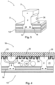
- Fig. 1 shows a composite element 1 not according to the invention in a sectional view.
- a first element 2 is formed by a cross-laminated timber panel 14, which has five cross-glued single-layer panels made of wood.
- a recess 5 is provided in the panel-shaped first element 2, wherein a cross-section of the recess 5 has side surfaces 19 in an upper region, which have an increasing distance from one another with increasing distance from a surface 10 in which the recess 5 is arranged.
- Such a cross-section is also called a dovetail cross-section and is usually introduced into the first element 2 by means of milling.
- a lattice girder 6 protruding from the recess 5 is fixed in the recess 5 by means of concrete 4 as a hardenable material, which lattice girder has two lower chords 12 and an upper chord 11.
- the Fig. 1 The composite element 1 shown can be manufactured completely in the factory or in a precast plant in an automated manner and with a high level of process reliability.
- a corresponding recess 5 is milled into the cross laminated timber panel 14 or the first element 2, after which the lattice girder 6 is positioned in the recess 5 and the recess 5 is filled with concrete 4 in order to fix the lattice girder 6 in the recess 5.
- Due to the dovetail-shaped cross section of the Recess 5 results in a positive connection between the second element 3 formed by the concrete 4 and the lattice girder 6 and the first element 2, which can also be loaded by a tensile force perpendicular to the surface 10.
- the composite element 1 according to the invention can be used, for example, to form a ceiling 13 if the second element 3 is supported at the end so that the first element 2 hangs on the second element 3.
- Fig. 2 shows a section of a ceiling 13 of a building, which is covered with a Fig. 1 illustrated composite element 1.
- the cross laminated timber panel 14 forms a wooden ceiling in which several approximately parallel and regularly spaced dovetail-shaped recesses 5 are positioned.
- a lattice girder 6 is arranged in each of the dovetail-shaped recesses 5 and is positively connected to the cross laminated timber panel 14 via concrete 4.
- the lattice girders 6 with the concrete 4 arranged in the recesses 5 thus form supports to which the cross laminated timber panel 14 is fastened via the dovetail cross section.
- Displacement bodies 30 which are U-shaped in cross section and designed as precast concrete parts 9 are positioned between the supports or the second elements 3.
- the displacement bodies 30 serve as a support surface for a floor 16 of a room arranged above. At the same time, the displacement bodies 30 form a formwork so that on a construction site, in-situ concrete or topping concrete 27 can be poured onto parts of the lattice girders 6 protruding from the recess 5 in order to connect the cross-laminated timber panel 14 to the precast concrete parts 9 via the concrete 4, the lattice girder 6 and the in-situ concrete or topping concrete 27, so that a stable ceiling 13 is formed.
- Cavities in the precast concrete elements 9 are used here for piping 18 to guide lines 29 such as installation lines.
- a Fig. 2 The ceiling 13 shown can be manufactured on a construction site with very little concreting effort, since only topping concrete 27 has to be applied to the parts of the lattice girders 6 protruding from the recess 5, while all other parts can be prefabricated. This makes it possible to manufacture a building with a very high degree of prefabrication.
- a self-supporting ceiling 13 is achieved in a simple manner, which has a visually appealing wooden underside and reinforced concrete girders.
- Fig. 3 shows a further composite element 1 not according to the invention, which is usually completely manufactured in advance in a prefabricated component factory by positioning a formwork above and to the side of the recess 5, after which the lattice girder 6 is completely cast in concrete 4.
- a composite element 1 designed in this way concreting on a construction site is no longer necessary, which is why, for example, a ceiling 13 can be manufactured entirely in a dry construction method.
- recesses 24 are provided in the concrete 4, through which cables 29 can also be guided transversely to a longitudinal extension of the beams made of concrete 4 or reinforced concrete, wherein the beams are usually elongated and protrude from one side wall 7 of a building to the next side wall 7 of the building.
- Such a ceiling 13 is for example in Fig. 4 As can be seen, even with such a ceiling 13, a cavity 21 is achieved between an upper side of a floor 16 of a storey of a building and an underside of a ceiling 13 of a storey below, in which cavity 21, for example, piping 18 can be positioned.
- a cavity 21 is achieved between an upper side of a floor 16 of a storey of a building and an underside of a ceiling 13 of a storey below, in which cavity 21, for example, piping 18 can be positioned.
- a cavity 21 is achieved between an upper side of a floor 16 of a storey of a building and an underside of a ceiling 13 of a storey below, in which cavity 21, for example, piping 18 can be positioned.
- Pipes 20 are arranged on the fiber mat 22 in order to be able to heat or cool an interior space.
- the second elements 3 made of concrete 4 or reinforced concrete, which are designed as supports, have recesses 24 here so that lines 29 can also be laid transversely or perpendicularly to a direction in which the supports run.
- the first element 2 is designed as a wooden ceiling, which consists of cross-glued single-layer panels and has a thickness of about 100 mm.
- a connection between a base 16 positioned above the second elements 3 and the second elements 3 is made via an elastic adhesive 17, which reduces vibrations. This achieves good sound insulation.
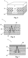
- Fig. 5 shows a further embodiment of a composite element 1 not according to the invention, wherein a thermal insulation 8 is arranged between the first element 2 and the second element 3.
- a composite element 1 is Usually manufactured by forming a composite element 1 in a first step according to Fig. 1 is formed, after which the thermal insulation 8 is positioned adjacent to the recess 5 on the first element 2, which is also designed here as a cross-laminated timber panel 14, after which topping concrete 27 is applied, which covers the reinforcement designed as a lattice girder 6 and the thermal insulation 8.
- the thermal insulation 8 is fixed in a form-fitting manner by the hardened topping concrete 27 and thus connected to the cross-laminated timber panel 14 and the second element 3 formed by concrete 4 and lattice girder 6.
- a wood-concrete composite panel formed in this way can advantageously be used as a thermally insulating ceiling 13 in a building, without the need for on-site concreting.
- Fig. 6 shows a composite element 1 according to Fig. 5 , wherein a displacement body 30 is positioned adjacent to the recess 5 on only one side and at a distance from the recess 5 on an opposite side, so that installation pipes can be arranged between the recess 5 and the insulation material, which are also enclosed in the concrete topping 27, which is applied in the second step after positioning the displacement body 30.
- the displacement body 30 can of course be designed in a variety of ways in order to achieve, for example, certain physical properties such as sound insulation, thermal insulation 8 or particularly high stability.
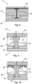
- Fig. 7 shows a further composite element 1 not according to the invention, in which an area above the first element 2, which is also designed here as a cross-laminated timber panel 14, is completely filled with concrete topping 27. Furthermore, a transverse reinforcement 28 is also provided in order to achieve a particularly high strength of the composite element 1 or a ceiling 13 of a building.
- the reinforcement can also be designed as a steel beam 15 instead of a lattice girder 6.
- a ceiling 13 of a building is in Fig. 8
- Concrete 4 is usually made of micro-fiber concrete, so that high strength and low shrinkage during hardening are achieved.
- Fig. 9 shows a further embodiment of a ceiling 13 of a building with a non-inventive composite element 1 according to Fig. 3 in sectional view.
- a floor 16 of an upper floor is formed by prefabricated panels 23, usually prefabricated concrete panels, which are connected to the second element 3 designed as a reinforced concrete beam via an elastic adhesive 17 in order to reduce vibrations.
- pipes 20 in a bulk material 31, usually a bulk material 31 available under the name Liapor Ground are arranged below the prefabricated panels 23, so that the ceiling 13 can be used for heating or cooling purposes.
- the bulk material 31 is arranged between the prefabricated panels 23 and the first element 2 designed as a cross-laminated timber panel 14 in order to achieve favorable building physics properties.
- Fig. 10 shows a section of another ceiling 13 with a composite element 1 not according to the invention.
- the ceiling 13 shown contains a second element 3 with reinforcement, which has four lower chords 12 and three upper chords 11, which are connected by steel elements (not shown) of the lattice girder 6. This achieves a very high level of strength, so that a large span can be achieved even with a low ceiling thickness.
- the ceiling 13 shown has floor elements designed as prefabricated panels 23, on which a floor covering 32 is positioned.
- a connection is made via an elastic adhesive 17 in order to reduce vibrations.
- the floor 16 of this ceiling 13 is formed by cross-glued single-layer panels or a cross-laminated timber panel 14 and a floor covering 32.
- Fig. 12 shows an area of a ceiling 13 with a composite element 1 not according to the invention, in which the composite element 1 is mounted on a side wall 7 formed by a cross-laminated timber panel 14 in a sectional view through a second element 3 designed as a support.
- the second element 3 partially protrudes into the side wall 7, so that forces from the ceiling 13 or the floor 16 can be transferred and diverted to the side wall 7 via the second element 3 designed as a support.
- the first element which is also designed as a wooden ceiling here, is supported by the second element 3 or hangs from the second element 3.
- Fig. 13 shows another section through the Fig. 12 illustrated ceiling 13 in an area between two second elements 3 or between two second elements 3. As can be seen, in this area the first element 2 designed as a wooden ceiling protrudes into the side wall 7.
- Fig. 14 shows a further ceiling 13 of a building with a composite element 1 not according to the invention.
- pipes 20 for heating or cooling are arranged above the second elements 3 in concrete slabs 33 in order to ensure efficient heat transfer.
- Fig. 15 shows an area in which a ceiling 13 of a building rests on side walls 7, the side walls 7 being formed by masonry 25 or bricks.
- the first element 2 designed as a wooden ceiling
- the second elements 3 designed as reinforced concrete beams.
- An elastic material is arranged between the ceiling 13 and the masonry 25 in order to achieve shell decoupling.
- a space between the masonry 25 and the composite element 1 is filled with a cast concrete 26.
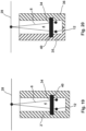
- Fig. 17 is a in Fig. 16 illustrated composite element 1 or a first element 2 of a corresponding composite element 1 in a top view.
- the six approximately arrow-shaped thrust cams 37 form positive connections between the first element 2 and the concrete 4 at several positions, so that thrust forces can be easily transmitted and high flexural rigidity and flexural strength are achieved.
- Six arrow-shaped thrust cams 37 are provided, with three thrust cams 37 oriented along the longitudinal direction and three thrust cams opposite to the longitudinal direction, so that several thrust cams 37 are arranged in opposite directions in the recess 5 in order to enable uniformly good transmission of forces along the longitudinal direction 39.
- this composite element 1 can also be used like the one in Fig. 17 shown along the longitudinal direction 39 have a plurality of arrow-shaped regions or arrow-shaped shear cams 37, in each of which a corresponding reinforcement is arranged in order to connect the concrete 4 to the first element 2 in a shear-resistant manner.
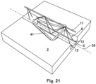
- the steel bracket 41 extends in regions along the oblique side edges 38 of the arrow-shaped region of the recess 5 and the oblique regions of the steel bracket 41 are connected by a part of the steel bracket 41 which is aligned approximately normal to a longitudinal direction 39 of the recess 5.
- a wooden ceiling in a building can be formed in a particularly cost-effective and process-reliable manner.
- visually appealing ceilings 13 can be formed at low cost and without concreting on the construction site.
Landscapes
- Engineering & Computer Science (AREA)
- Architecture (AREA)
- Civil Engineering (AREA)
- Structural Engineering (AREA)
- Physics & Mathematics (AREA)
- Electromagnetism (AREA)
- Chemical & Material Sciences (AREA)
- Composite Materials (AREA)
- Rod-Shaped Construction Members (AREA)
- Sliding-Contact Bearings (AREA)
Claims (15)
- Procédé, destiné à fabriquer un élément composite (1), caractérisé en ce que l'on met à disposition un premier élément (2) pourvu d'un évidement (5), lequel évidement (5) s'étend sensiblement le long d'une direction longitudinale (39) et comporte une section transversale variable le long de la direction longitudinale (39) avec des cames de poussée (37) en forme de flèches, lesquelles sont conçues sous la forme d'évidements dotés de zones plus larges et plus étroites le long de la direction longitudinale (39), suite à quoi, l'on positionne dans l'évidement (5) une armature saillant partiellement hors de l'évidement (5), suite à quoi, l'on remplit l'évidement (5) d'une matière durcissable, notamment de béton (4), suite à quoi la matière durcissable durcit dans l'évidement (5) en constituant un deuxième élément (3), de sorte que l'armature soit assemblée par complémentarité de forme avec le premier élément (2) par l'intermédiaire de la matière durcie, dans l'évidement (5) étant positionnée une pièce métallique constituée d'un étrier d'acier (41), laquelle est orientée au moins par endroits sous un angle de 45 degrés à 135 degrés, notamment de 80 degrés à 100 degrés, par rapport à la direction longitudinale (39) de l'évidement (5) et est assemblée avec des membrures inférieures (12) de l'armature et s'étend dans les zones les plus larges des cames de poussée (37), caractérisé en ce que qu'une pièce métallique constituée d'un étrier d'acier s'étend par endroits le long d'arêtes latérales (38) obliques des cames de poussée (37) en forme de flèches, des zones obliques de l'étrier d'acier (41) étant assemblées par une partie de l'étrier d'acier (41) orientée approximativement à la normale d'une direction longitudinale (39) de l'évidement, de telle sorte qu'un écart localement supérieur entre les membrures inférieures (12) soit mécaniquement stabilisé au moyen de l'étrier d'acier (41).
- Procédé selon la revendication 1, caractérisé en ce que l'on positionne sur le premier élément (2), de manière adjacente à l'évidement (5) un corps de refoulement (30), de préférence une matière de charge, un corps creux et / ou un coffrage, suite à quoi, l'on applique une matière durcissable, notamment du béton fibré, de préférence du béton microfibré sur la partie de l'armature qui saillit hors de l'évidement (5), de sorte que l'armature soit sensiblement enfermée dans la matière durcissable, de préférence, la matière durcissable étant appliquée de telle sorte qu'une fois que la matière durcissable a durci, le corps de refoulement (30) soit fixé par ladite matière par rapport au premier élément (2).
- Procédé selon la revendication 1 ou 2, caractérisé en ce que le premier élément (2) est constitué en ce que l'on met à disposition au moins deux éléments partiels (35, 36) que l'on assemble, un assemblage des éléments partiels (35, 36) ayant lieu notamment par l'intermédiaire d'un élément d'assemblage, de préférence un mandrin, lequel est assemblé sur une première extrémité avec un premier élément partiel (35) et sur une deuxième extrémité avec un deuxième élément partiel (36) et s'étend à travers l'évidement (5) .
- Procédé, destiné à fabriquer un bâtiment, caractérisé en ce que l'on met en oeuvre un élément composite (1) fabriqué selon l'une quelconque des revendications 1 à 3.
- Procédé selon la revendication 4, caractérisé en ce que dans une première étape, l'on remplit l'évidement (5) dans une usine de préfabrication avec une matière durcissable, laquelle durcit dans l'évidement (5), suite à quoi, l'on transporte l'élément composite (1) sur un chantier et on le place de manière adjacente à d'autres pièces de constructions, suite à quoi, dans une deuxième étape, l'on applique une matière durcissable supplémentaire sur une partie de l'armature qui saillit hors de l'évidement (5), de telle sorte que lors du durcissement de ladite matière durcissable, l'élément composite (1) soit assemblé par l'intermédiaire de la deuxième matière durcissable avec les autres pièces de construction.
- Procédé selon la revendication 4, caractérisé en ce que l'on applique préalablement l'ensemble de la matière durcissable, par exemple dans une usine de pièce finies, suite à quoi, l'on transporte l'élément composite (1) sur un chantier, sur lequel l'on assemble l'élément composite (1) avec d'autres pièces de construction du bâtiment, sensiblement sans mettre en œuvre un matériau de construction contenant de l'eau.
- Elément composite (1), comportant un premier élément (2) pourvu d'un évidement (5) doté d'une section transversale variable le long d'un direction longitudinale (39), l'évidement (5) comportant le long d'une direction longitudinale (39) des cames de poussée (37) comportant des zones plus larges et plus étroites et au moins un deuxième élément (3) assemblé avec le premier élément (2), lequel comporte une matière durcissable et une armature, l'au moins un deuxième élément (3) saillant au moins partiellement hors d'un évidement (5) du premier élément (2) et étant assemblé par complémentarité de forme dans l'évidement (5) avec le premier élément (2), l'élément composite (1) étant fabriqué notamment au cours d'un procédé selon l'une quelconque des revendications 1 à 6, dans l'évidement (5) étant positionnée une pièce métallique constituée d'un étrier d'acier (41), lequel s'étend à l'intérieur des zones plus larges et est orienté au moins par endroits sous un angle de 45 degrés à 135 degrés, notamment de 80 degrés à 100 degrés par rapport à une direction longitudinale (39) de l'évidement (5) et est assemblé avec des membrures inférieures (12) de l'armature, caractérisé en ce que la pièce métallique constituée d'un étrier d'acier est par endroits approximativement parallèle à une arête latérale (38) oblique de la cames de poussée (37) en forme de flèche de l'évidement (5), de telle sorte qu'un écart localement supérieur entre les membrures inférieures (12) soit mécaniquement stabilisé au moyen de l'étrier d'acier (41).
- Elément composite (1) selon la revendication 7, caractérisé en ce que l'armature est conçue sous la forme d'un support en treillis (6), deux membrures inférieures (12) et une membrure supérieure (11) étant prévues et les membrures inférieures (12) étant positionnées dans l'évidement (5).
- Elément composite (1) selon la revendication 7 ou 8, caractérisé en ce que l'évidement (5) est conçu au moins par endroits avec des arêtes latérales (38) effilées, dans une vue en élévation.
- Elément composite (1) selon l'une quelconque des revendications 7 à 9, caractérisé en ce que l'évidement (5) est conçu de forme allongée et est latéralement fermé.
- Elément composite (1) selon l'une quelconque des revendications 7 à 10, caractérisé en ce qu'au moins deux cames de poussée sont orientées à contresens.
- Elément composite (1) selon l'une quelconque des revendications 7 à 11, caractérisé en ce que l'armature est conçue sous la forme d'une armature textile, dotée notamment de fibres de verre et / ou de carbone.
- Bâtiment comprenant un élément composite (1), caractérisé en ce que l'élément composite (1) est conçu selon l'une quelconque des revendications 7 à 12, de préférence le premier élément (2) formant un plafond (13) d'un espace intérieur, lequel est porté sensiblement par au moins un deuxième élément (3).
- Bâtiment selon la revendication 13, caractérisé en ce que l'au moins un deuxième élément (3) est conçu sous la forme d'un support en I.
- Bâtiment selon la revendication 13 ou 14, caractérisé en ce que dans le deuxième élément (3) sont positionnés des tubes (20), pour permettre un chauffage ou un refroidissement du bâtiment par l'élément composite (1).
Priority Applications (1)
| Application Number | Priority Date | Filing Date | Title |
|---|---|---|---|
| EP24217500.8A EP4497890A3 (fr) | 2021-05-07 | 2021-05-07 | Procédé de fabrication d'un élément composite et élément composite |
Applications Claiming Priority (1)
| Application Number | Priority Date | Filing Date | Title |
|---|---|---|---|
| PCT/AT2021/060158 WO2022232851A1 (fr) | 2021-05-07 | 2021-05-07 | Procédé de fabrication d'un élément composite et élément composite |
Related Child Applications (1)
| Application Number | Title | Priority Date | Filing Date |
|---|---|---|---|
| EP24217500.8A Division EP4497890A3 (fr) | 2021-05-07 | 2021-05-07 | Procédé de fabrication d'un élément composite et élément composite |
Publications (3)
| Publication Number | Publication Date |
|---|---|
| EP4334541A1 EP4334541A1 (fr) | 2024-03-13 |
| EP4334541C0 EP4334541C0 (fr) | 2024-12-25 |
| EP4334541B1 true EP4334541B1 (fr) | 2024-12-25 |
Family
ID=75953803
Family Applications (2)
| Application Number | Title | Priority Date | Filing Date |
|---|---|---|---|
| EP24217500.8A Pending EP4497890A3 (fr) | 2021-05-07 | 2021-05-07 | Procédé de fabrication d'un élément composite et élément composite |
| EP21726032.2A Active EP4334541B1 (fr) | 2021-05-07 | 2021-05-07 | Procédé de fabrication d'un élément composite et élément composite |
Family Applications Before (1)
| Application Number | Title | Priority Date | Filing Date |
|---|---|---|---|
| EP24217500.8A Pending EP4497890A3 (fr) | 2021-05-07 | 2021-05-07 | Procédé de fabrication d'un élément composite et élément composite |
Country Status (2)
| Country | Link |
|---|---|
| EP (2) | EP4497890A3 (fr) |
| WO (1) | WO2022232851A1 (fr) |
Family Cites Families (4)
| Publication number | Priority date | Publication date | Assignee | Title |
|---|---|---|---|---|
| FR1010564A (fr) * | 1948-09-10 | 1952-06-12 | Procédé de fabrication de poutres ou de plafonds en béton et poutres ou plafonds réalisés d'après ce procédé | |
| FR2780427B1 (fr) * | 1998-06-30 | 2002-09-06 | Georges Deperraz | Poutre mixte bois-beton pour la construction et l'ouvrage d'art |
| FR2876718B1 (fr) * | 2004-10-19 | 2009-01-23 | Claude Blouet | Coffrage bois d'armature de poutre de plancher beton |
| AT518496B1 (de) * | 2016-04-13 | 2021-12-15 | Hans Ulrich Terkl | Verfahren zur Herstellung eines Verbundelementes sowie Verbundelement |
-
2021
- 2021-05-07 EP EP24217500.8A patent/EP4497890A3/fr active Pending
- 2021-05-07 WO PCT/AT2021/060158 patent/WO2022232851A1/fr not_active Ceased
- 2021-05-07 EP EP21726032.2A patent/EP4334541B1/fr active Active
Also Published As
| Publication number | Publication date |
|---|---|
| WO2022232851A1 (fr) | 2022-11-10 |
| EP4334541A1 (fr) | 2024-03-13 |
| EP4497890A3 (fr) | 2025-03-05 |
| EP4497890A2 (fr) | 2025-01-29 |
| EP4334541C0 (fr) | 2024-12-25 |
Similar Documents
| Publication | Publication Date | Title |
|---|---|---|
| AT523599B1 (de) | Verfahren zur Herstellung eines Verbundelementes sowie Verbundelement | |
| EP2787140B1 (fr) | Plafond plat en structure composite bois-béton et procédé de fabrication d'un tel plafond plat | |
| DE19818525B4 (de) | Holz-Beton-Verbundelement | |
| EP3191657B1 (fr) | Coffrage perdu en béton haute performance ou ultra haute performance | |
| EP2146017A1 (fr) | Composant pour dalles de plancher ou de toiture ainsi que procédé destiné à la fabrication d'un composant | |
| AT518496B1 (de) | Verfahren zur Herstellung eines Verbundelementes sowie Verbundelement | |
| EP0121685B1 (fr) | Elément soumis à la compression dans un élément de construction isolant pour parties de bâtiment faisant ressaut | |
| EP1482101B1 (fr) | Elément de construction, procédé pour fabriquer des éléments de construction et moyens de liaison pour élément de construction | |
| EP3296476B1 (fr) | Dispositif de liaison d'un mur de bâtiment à une dalle de sol ou de plafond et élément de moulage d'un tel système | |
| EP4334541B1 (fr) | Procédé de fabrication d'un élément composite et élément composite | |
| EP3919702A1 (fr) | Composant composite bois-béton et procédé de formation d'un composant composite bois-béton | |
| DE102015200661B4 (de) | Verbundfertigteil | |
| EP3789553B1 (fr) | Élément préfabriqué et système préfabriqué | |
| EP3296478B1 (fr) | Dispositif de liaison d'un mur de bâtiment à une dalle de sol ou de plafond et élément de moulage d'un tel système | |
| AT515862B1 (de) | Verbundelement sowie Verfahren zur Herstellung desselben | |
| EP1422356B1 (fr) | Panneau de construction préfabriqué avec de l'isolant et des tubes de chauffage noyés dans le béton et méthode de fabrication | |
| EP2063037A1 (fr) | Plafond pour une construction | |
| AT414334B (de) | Bausteinverbund | |
| DE10066165B4 (de) | Wärmedämmverbundsystem sowie bandförmiges Element für die Befestigung von Dämmstoffelementen | |
| EP3912778B1 (fr) | Procédé de fabrication à plat d'une pièce porteuse verticale préfabriquée en béton et pièce porteuse verticale préfabriquée en béton | |
| EP4707488A1 (fr) | Demi-produit, élément de construction composite bois-béton, utilisation et procédé | |
| EP3467220B1 (fr) | Partie de bâtiment et procédé de fabrication d'une telle partie de bâtiment | |
| DE20018907U1 (de) | Dämmstoffelement und Wärmedämmverbundsystem für die Dämmung von Gebäudefassaden | |
| DE102023128557A1 (de) | Deckensegment, Holzdecke, Gebäude und Verfahren | |
| DE102020007552A1 (de) | Bauelement und Verfahren zur Herstellung eines Bauelements |
Legal Events
| Date | Code | Title | Description |
|---|---|---|---|
| STAA | Information on the status of an ep patent application or granted ep patent |
Free format text: STATUS: UNKNOWN |
|
| STAA | Information on the status of an ep patent application or granted ep patent |
Free format text: STATUS: THE INTERNATIONAL PUBLICATION HAS BEEN MADE |
|
| PUAI | Public reference made under article 153(3) epc to a published international application that has entered the european phase |
Free format text: ORIGINAL CODE: 0009012 |
|
| STAA | Information on the status of an ep patent application or granted ep patent |
Free format text: STATUS: REQUEST FOR EXAMINATION WAS MADE |
|
| 17P | Request for examination filed |
Effective date: 20231025 |
|
| AK | Designated contracting states |
Kind code of ref document: A1 Designated state(s): AL AT BE BG CH CY CZ DE DK EE ES FI FR GB GR HR HU IE IS IT LI LT LU LV MC MK MT NL NO PL PT RO RS SE SI SK SM TR |
|
| DAV | Request for validation of the european patent (deleted) | ||
| DAX | Request for extension of the european patent (deleted) | ||
| GRAP | Despatch of communication of intention to grant a patent |
Free format text: ORIGINAL CODE: EPIDOSNIGR1 |
|
| STAA | Information on the status of an ep patent application or granted ep patent |
Free format text: STATUS: GRANT OF PATENT IS INTENDED |
|
| INTG | Intention to grant announced |
Effective date: 20240918 |
|
| GRAS | Grant fee paid |
Free format text: ORIGINAL CODE: EPIDOSNIGR3 |
|
| GRAA | (expected) grant |
Free format text: ORIGINAL CODE: 0009210 |
|
| STAA | Information on the status of an ep patent application or granted ep patent |
Free format text: STATUS: THE PATENT HAS BEEN GRANTED |
|
| AK | Designated contracting states |
Kind code of ref document: B1 Designated state(s): AL AT BE BG CH CY CZ DE DK EE ES FI FR GB GR HR HU IE IS IT LI LT LU LV MC MK MT NL NO PL PT RO RS SE SI SK SM TR |
|
| REG | Reference to a national code |
Ref country code: GB Ref legal event code: FG4D Free format text: NOT ENGLISH |
|
| REG | Reference to a national code |
Ref country code: CH Ref legal event code: EP |
|
| REG | Reference to a national code |
Ref country code: DE Ref legal event code: R096 Ref document number: 502021006213 Country of ref document: DE |
|
| REG | Reference to a national code |
Ref country code: IE Ref legal event code: FG4D Free format text: LANGUAGE OF EP DOCUMENT: GERMAN |
|
| U01 | Request for unitary effect filed |
Effective date: 20241231 |
|
| U07 | Unitary effect registered |
Designated state(s): AT BE BG DE DK EE FI FR IT LT LU LV MT NL PT RO SE SI Effective date: 20250114 |
|
| PG25 | Lapsed in a contracting state [announced via postgrant information from national office to epo] |
Ref country code: HR Free format text: LAPSE BECAUSE OF FAILURE TO SUBMIT A TRANSLATION OF THE DESCRIPTION OR TO PAY THE FEE WITHIN THE PRESCRIBED TIME-LIMIT Effective date: 20241225 |
|
| PG25 | Lapsed in a contracting state [announced via postgrant information from national office to epo] |
Ref country code: NO Free format text: LAPSE BECAUSE OF FAILURE TO SUBMIT A TRANSLATION OF THE DESCRIPTION OR TO PAY THE FEE WITHIN THE PRESCRIBED TIME-LIMIT Effective date: 20250325 |
|
| PG25 | Lapsed in a contracting state [announced via postgrant information from national office to epo] |
Ref country code: GR Free format text: LAPSE BECAUSE OF FAILURE TO SUBMIT A TRANSLATION OF THE DESCRIPTION OR TO PAY THE FEE WITHIN THE PRESCRIBED TIME-LIMIT Effective date: 20250326 |
|
| PG25 | Lapsed in a contracting state [announced via postgrant information from national office to epo] |
Ref country code: RS Free format text: LAPSE BECAUSE OF FAILURE TO SUBMIT A TRANSLATION OF THE DESCRIPTION OR TO PAY THE FEE WITHIN THE PRESCRIBED TIME-LIMIT Effective date: 20250325 |
|
| U20 | Renewal fee for the european patent with unitary effect paid |
Year of fee payment: 5 Effective date: 20250424 |
|
| PG25 | Lapsed in a contracting state [announced via postgrant information from national office to epo] |
Ref country code: SM Free format text: LAPSE BECAUSE OF FAILURE TO SUBMIT A TRANSLATION OF THE DESCRIPTION OR TO PAY THE FEE WITHIN THE PRESCRIBED TIME-LIMIT Effective date: 20241225 |
|
| PG25 | Lapsed in a contracting state [announced via postgrant information from national office to epo] |
Ref country code: PL Free format text: LAPSE BECAUSE OF FAILURE TO SUBMIT A TRANSLATION OF THE DESCRIPTION OR TO PAY THE FEE WITHIN THE PRESCRIBED TIME-LIMIT Effective date: 20241225 |
|
| PG25 | Lapsed in a contracting state [announced via postgrant information from national office to epo] |
Ref country code: ES Free format text: LAPSE BECAUSE OF FAILURE TO SUBMIT A TRANSLATION OF THE DESCRIPTION OR TO PAY THE FEE WITHIN THE PRESCRIBED TIME-LIMIT Effective date: 20241225 |
|
| PGFP | Annual fee paid to national office [announced via postgrant information from national office to epo] |
Ref country code: GB Payment date: 20250527 Year of fee payment: 5 |
|
| PG25 | Lapsed in a contracting state [announced via postgrant information from national office to epo] |
Ref country code: IS Free format text: LAPSE BECAUSE OF FAILURE TO SUBMIT A TRANSLATION OF THE DESCRIPTION OR TO PAY THE FEE WITHIN THE PRESCRIBED TIME-LIMIT Effective date: 20250425 |
|
| PGFP | Annual fee paid to national office [announced via postgrant information from national office to epo] |
Ref country code: CH Payment date: 20250601 Year of fee payment: 5 |
|
| PG25 | Lapsed in a contracting state [announced via postgrant information from national office to epo] |
Ref country code: SK Free format text: LAPSE BECAUSE OF FAILURE TO SUBMIT A TRANSLATION OF THE DESCRIPTION OR TO PAY THE FEE WITHIN THE PRESCRIBED TIME-LIMIT Effective date: 20241225 |
|
| PG25 | Lapsed in a contracting state [announced via postgrant information from national office to epo] |
Ref country code: CZ Free format text: LAPSE BECAUSE OF FAILURE TO SUBMIT A TRANSLATION OF THE DESCRIPTION OR TO PAY THE FEE WITHIN THE PRESCRIBED TIME-LIMIT Effective date: 20241225 |
|
| PLBE | No opposition filed within time limit |
Free format text: ORIGINAL CODE: 0009261 |
|
| STAA | Information on the status of an ep patent application or granted ep patent |
Free format text: STATUS: NO OPPOSITION FILED WITHIN TIME LIMIT |
|
| 26N | No opposition filed |
Effective date: 20250926 |
|
| PG25 | Lapsed in a contracting state [announced via postgrant information from national office to epo] |
Ref country code: MC Free format text: LAPSE BECAUSE OF FAILURE TO SUBMIT A TRANSLATION OF THE DESCRIPTION OR TO PAY THE FEE WITHIN THE PRESCRIBED TIME-LIMIT Effective date: 20241225 |
|
| PG25 | Lapsed in a contracting state [announced via postgrant information from national office to epo] |
Ref country code: IE Free format text: LAPSE BECAUSE OF NON-PAYMENT OF DUE FEES Effective date: 20250507 |