EP4334552B1 - Betätigungsvorrichtung für eine schlossvorrichtung und schlossvorrichtung - Google Patents
Betätigungsvorrichtung für eine schlossvorrichtung und schlossvorrichtung Download PDFInfo
- Publication number
- EP4334552B1 EP4334552B1 EP22723594.2A EP22723594A EP4334552B1 EP 4334552 B1 EP4334552 B1 EP 4334552B1 EP 22723594 A EP22723594 A EP 22723594A EP 4334552 B1 EP4334552 B1 EP 4334552B1
- Authority
- EP
- European Patent Office
- Prior art keywords
- wheel
- actuating
- actuating device
- transfer
- axis
- Prior art date
- Legal status (The legal status is an assumption and is not a legal conclusion. Google has not performed a legal analysis and makes no representation as to the accuracy of the status listed.)
- Active
Links
Images


Classifications
-
- E—FIXED CONSTRUCTIONS
- E05—LOCKS; KEYS; WINDOW OR DOOR FITTINGS; SAFES
- E05B—LOCKS; ACCESSORIES THEREFOR; HANDCUFFS
- E05B47/00—Operating or controlling locks or other fastening devices by electric or magnetic means
- E05B47/06—Controlling mechanically-operated bolts by electro-magnetically-operated detents
-
- E—FIXED CONSTRUCTIONS
- E05—LOCKS; KEYS; WINDOW OR DOOR FITTINGS; SAFES
- E05B—LOCKS; ACCESSORIES THEREFOR; HANDCUFFS
- E05B47/00—Operating or controlling locks or other fastening devices by electric or magnetic means
- E05B47/0001—Operating or controlling locks or other fastening devices by electric or magnetic means with electric actuators; Constructional features thereof
- E05B47/0012—Operating or controlling locks or other fastening devices by electric or magnetic means with electric actuators; Constructional features thereof with rotary electromotors
-
- E—FIXED CONSTRUCTIONS
- E05—LOCKS; KEYS; WINDOW OR DOOR FITTINGS; SAFES
- E05B—LOCKS; ACCESSORIES THEREFOR; HANDCUFFS
- E05B47/00—Operating or controlling locks or other fastening devices by electric or magnetic means
- E05B47/02—Movement of the bolt by electromagnetic means; Adaptation of locks, latches, or parts thereof, for movement of the bolt by electromagnetic means
- E05B47/023—Movement of the bolt by electromagnetic means; Adaptation of locks, latches, or parts thereof, for movement of the bolt by electromagnetic means the bolt moving pivotally or rotatively
-
- E—FIXED CONSTRUCTIONS
- E05—LOCKS; KEYS; WINDOW OR DOOR FITTINGS; SAFES
- E05B—LOCKS; ACCESSORIES THEREFOR; HANDCUFFS
- E05B47/00—Operating or controlling locks or other fastening devices by electric or magnetic means
- E05B47/06—Controlling mechanically-operated bolts by electro-magnetically-operated detents
- E05B47/0657—Controlling mechanically-operated bolts by electro-magnetically-operated detents by locking the handle, spindle, follower or the like
- E05B47/0665—Controlling mechanically-operated bolts by electro-magnetically-operated detents by locking the handle, spindle, follower or the like radially
- E05B47/0673—Controlling mechanically-operated bolts by electro-magnetically-operated detents by locking the handle, spindle, follower or the like radially with a rectilinearly moveable blocking element
-
- E—FIXED CONSTRUCTIONS
- E05—LOCKS; KEYS; WINDOW OR DOOR FITTINGS; SAFES
- E05B—LOCKS; ACCESSORIES THEREFOR; HANDCUFFS
- E05B47/00—Operating or controlling locks or other fastening devices by electric or magnetic means
- E05B47/06—Controlling mechanically-operated bolts by electro-magnetically-operated detents
- E05B47/0676—Controlling mechanically-operated bolts by electro-magnetically-operated detents by disconnecting the handle
- E05B47/068—Controlling mechanically-operated bolts by electro-magnetically-operated detents by disconnecting the handle axially, i.e. with an axially disengaging coupling element
-
- E—FIXED CONSTRUCTIONS
- E05—LOCKS; KEYS; WINDOW OR DOOR FITTINGS; SAFES
- E05B—LOCKS; ACCESSORIES THEREFOR; HANDCUFFS
- E05B1/00—Knobs or handles for wings; Knobs, handles, or press buttons for locks or latches on wings
- E05B1/0084—Handles or knobs with displays, signs, labels pictures, or the like
-
- E—FIXED CONSTRUCTIONS
- E05—LOCKS; KEYS; WINDOW OR DOOR FITTINGS; SAFES
- E05B—LOCKS; ACCESSORIES THEREFOR; HANDCUFFS
- E05B47/00—Operating or controlling locks or other fastening devices by electric or magnetic means
- E05B47/0001—Operating or controlling locks or other fastening devices by electric or magnetic means with electric actuators; Constructional features thereof
- E05B2047/0014—Constructional features of actuators or power transmissions therefor
- E05B2047/0018—Details of actuator transmissions
- E05B2047/002—Geared transmissions
-
- E—FIXED CONSTRUCTIONS
- E05—LOCKS; KEYS; WINDOW OR DOOR FITTINGS; SAFES
- E05B—LOCKS; ACCESSORIES THEREFOR; HANDCUFFS
- E05B47/00—Operating or controlling locks or other fastening devices by electric or magnetic means
- E05B47/0001—Operating or controlling locks or other fastening devices by electric or magnetic means with electric actuators; Constructional features thereof
- E05B2047/0014—Constructional features of actuators or power transmissions therefor
- E05B2047/0018—Details of actuator transmissions
- E05B2047/0026—Clutches, couplings or braking arrangements
- E05B2047/0031—Clutches, couplings or braking arrangements of the elastic type
-
- E—FIXED CONSTRUCTIONS
- E05—LOCKS; KEYS; WINDOW OR DOOR FITTINGS; SAFES
- E05B—LOCKS; ACCESSORIES THEREFOR; HANDCUFFS
- E05B47/00—Operating or controlling locks or other fastening devices by electric or magnetic means
- E05B2047/0048—Circuits, feeding, monitoring
- E05B2047/0057—Feeding
- E05B2047/0062—Feeding by generator
-
- E—FIXED CONSTRUCTIONS
- E05—LOCKS; KEYS; WINDOW OR DOOR FITTINGS; SAFES
- E05B—LOCKS; ACCESSORIES THEREFOR; HANDCUFFS
- E05B47/00—Operating or controlling locks or other fastening devices by electric or magnetic means
- E05B47/0001—Operating or controlling locks or other fastening devices by electric or magnetic means with electric actuators; Constructional features thereof
-
- E—FIXED CONSTRUCTIONS
- E05—LOCKS; KEYS; WINDOW OR DOOR FITTINGS; SAFES
- E05B—LOCKS; ACCESSORIES THEREFOR; HANDCUFFS
- E05B47/00—Operating or controlling locks or other fastening devices by electric or magnetic means
- E05B47/06—Controlling mechanically-operated bolts by electro-magnetically-operated detents
- E05B47/0611—Cylinder locks with electromagnetic control
- E05B47/0615—Cylinder locks with electromagnetic control operated by handles, e.g. by knobs
-
- G—PHYSICS
- G07—CHECKING-DEVICES
- G07C—TIME OR ATTENDANCE REGISTERS; REGISTERING OR INDICATING THE WORKING OF MACHINES; GENERATING RANDOM NUMBERS; VOTING OR LOTTERY APPARATUS; ARRANGEMENTS, SYSTEMS OR APPARATUS FOR CHECKING NOT PROVIDED FOR ELSEWHERE
- G07C9/00—Individual registration on entry or exit
- G07C9/00174—Electronically operated locks; Circuits therefor; Nonmechanical keys therefor, e.g. passive or active electrical keys or other data carriers without mechanical keys
- G07C9/00563—Electronically operated locks; Circuits therefor; Nonmechanical keys therefor, e.g. passive or active electrical keys or other data carriers without mechanical keys using personal physical data of the operator, e.g. finger prints, retinal images, voicepatterns
Definitions
- the present invention generally relates to an actuating device for a lock device.
- an actuating device comprising a manually rotatable actuating element, and a lock device comprising an actuating device, are provided.
- EP 0787874 B1 discloses an electronic door lock comprising a knob and a keypad distanced from the knob.
- EP 0962612 A2 discloses a lock cylinder comprising a cylinder housing, a knob rotatable about an axis of rotation and having an inner housing, a reader unit arranged in the inner housing, a lock member and a coupling.
- the knob further comprises an internal toothing.
- DE 102004017664 A1 discloses a mechatronic lock cylinder comprising cylinder extension, communication elements accommodated in the cylinder extension, a manual drive element rotatable about an axis of rotation and having an internal toothing, a rotatable lock bit, and an electromechanical switching element for transmitting a force from the manual drive element to a cylinder core and to the lock bit.
- a still further object of the present invention is to provide an actuating device for a lock device, which actuating device enables a user to more reliably provide a credential input.
- a still further object of the present invention is to provide an actuating device for a lock device, which actuating device solves several or all of the foregoing objects in combination.
- a still further object of the present invention is to provide a lock device comprising an actuating device, which lock device solves one, several or all of the foregoing objects.
- an actuating device for a lock device according to claim 1.
- the actuating device thus has a static credential receiver arranged at least partly inside the actuating element, such as at least partly inside a knob. This contributes to a compact design of the actuating device.
- the credential receiver remains static. The actuating device thereby also provides a consistent user experience.
- a major portion of the credential receiver may be arranged radially inside the actuating element with respect to the actuation axis.
- the credential receiver may be arranged entirely radially inside the actuating element with respect to the actuation axis.
- a major length of the credential receiver along the actuation axis may be arranged radially inside the actuating element.
- a length of the credential receiver is thus a dimension of the credential receiver along the actuation axis or parallel with the actuation axis.
- the credential receiver provides a credential interface between the user and the actuating device.
- the credential receiver may be of a wide range of types.
- the credential receiver may for example comprise a biometric sensor, a keypad, a display and/or an antenna.
- the credential input may be various types of biometric traits of a person, such as fingerprint, iris, face and/or voice.
- the credential receiver comprises a keypad or a display
- the credential input may be a code input by a person to the keypad or the display.
- the credential receiver comprises an antenna
- the credential input may be a wireless signal from a wireless key device, such as an RFID (radio-frequency identification) card or a mobile phone.
- the credential receiver may be configured to issue an access signal in response to the credential input.
- the access signal may then be evaluated by a control system of the actuating device. Due to the stationary structure inside the actuating element, the actuating device enables various types of credential receivers to be easily installed in the actuating device.
- the transfer device may comprise an input element and an output element.
- the input element may be driven to rotate by rotation of the actuating element.
- the output element may be fixed to, or integrally formed with, the locking member.
- the transfer device may for example be a coupling device or a blocking device.
- the input element may be decoupled from the output element in the disabled state and may be coupled to the output element in the enabled state.
- the actuating element can always be rotated.
- the transfer device is a blocking device
- the input element may be fixed to, or integrally formed with, the output element.
- the input element may be blocked in the disabled state and may be unblocked in the enabled state.
- the actuating element can only be rotated when the transfer device adopts the enabled state.
- the disabled state and the enabled state may alternatively be referred to as a locked state and an unlocked state, respectively.
- the actuating device may further comprise a lock cylinder.
- the lock cylinder may form part of the stationary structure.
- the transfer device may be provided in the lock cylinder.
- Static components inside the actuating element may be secured to the lock cylinder, e.g. by one or more fasteners, such as screws.
- the actuating element may comprise a cavity for accommodating the stationary structure, or a part of the stationary structure, therein.
- the actuating device further comprises a transfer wheel rotatable about a transfer axis parallel with the actuation axis.
- the transfer wheel is positioned radially inside the actuating element with respect to the actuation axis.
- the transfer wheel is arranged to drive an input element of the transfer device.
- the actuating element comprises an internal profile engaging the transfer wheel.
- the internal profile may be circular.
- a diameter of the transfer wheel may be at least 20 %, such as at least 40 %, of a diameter of the internal profile.
- the diameter of the transfer wheel may be less than 90 %, such as less than 70 %, of the diameter of the internal profile.
- stationary components such as cables and fasteners, can pass through the internal profile without interfering with the movements of the internal profile and the transfer wheel.
- the transfer wheel can transmit a movement of the actuating element to a movement of the transfer device (e.g. the input element thereof) at the same time as the stationary structure passes through the internal profile, i.e. through a space inside the internal profile.
- the internal profile may be concentric with the actuation axis.
- the transfer axis may be stationary.
- the input element may be rotatable.
- the transfer wheel may be fixed to, or integrally formed with, the input element.
- the actuating device may comprise a transmission between the transfer wheel and the input element. In this case, the input element does not have to move by rotation.
- the actuating device further comprises a second wheel rotatable about a second axis and a third wheel rotatable about a third axis.
- Each of the second axis and the third axis is parallel with the actuation axis, and each of the second wheel and the third wheel is positioned radially inside the actuating element with respect to the actuation axis.
- the internal profile engages each of the second wheel and the third wheel.
- the transfer wheel may be larger than the second wheel.
- the transfer wheel may be made as large as possible in view of the needed area for the stationary structure through the internal profile and the second wheel may be made as small as possible.
- the input element can rotate relatively slowly and the second wheel can rotate relatively fast (e.g. to drive a generator) for a given rotational speed of the actuating element.
- the actuating device comprises the three wheels, the third wheel centers the actuating element with respect to the actuation axis.
- Each of the second axis and the third axis may be stationary.
- the actuating element Since the internal profile engages each of the three wheels, the actuating element is supported by the three wheels.
- the support of the actuating element on three wheels reduces the friction counteracting the rotation of the actuating element, for example in contrast to a large support wheel having an external diameter corresponding to the internal diameter of the internal profile.
- the transfer wheel may alternatively be referred to as a first wheel.
- the first wheel, the second wheel and the third wheel may lie in a common plane perpendicular to the actuation axis.
- the first wheel, the second wheel and the third wheel may provide the only support of the actuating element in radial directions with respect to the actuation axis.
- One, several or all of the transfer wheel, the second wheel and the third wheel may be a gear wheel.
- the internal profile may comprise an internal gear meshing with the one or more gear wheels.
- the actuating device comprises a gear train.
- the one or more gear wheels and the internal gear may be spur gears.
- the teeth of the internal gear face radially inwards with respect to the actuation axis.
- the actuating element may comprise a ring gear comprising the internal profile with the internal gear.
- each wheel may be a friction wheel and the internal profile may comprise a friction surface frictionally engaging each of the one or more friction wheels.
- frictional surfaces may for example comprise rubber.
- the actuating element may comprise a knob.
- the knob may be cylindrical and/or hollow.
- the internal profile may be fixed to the knob.
- the ring gear may be fixed to the knob.
- the internal profile may be provided in a rear region of the knob, such as within 20 % of a length of the knob along the actuation axis from a rear end of the knob.
- a diameter of the internal profile may be at least 50 %, such as at least 70 %, of an external diameter of the knob.
- the actuating element may comprise a front end.
- the credential receiver may be substantially aligned with, or aligned with, the front end.
- the actuating device can provide a static front face.
- a substantial alignment may include offsetting a front side of the credential receiver less than 10 % of the length of the knob from the front end.
- the actuating device may further comprise a control system.
- the control system may be configured to issue an authorization signal to the transfer device upon presentation of a valid credential input by the user.
- the control system may be arranged in the stationary structure. In this way, the control system does not rotate together with any of the actuating element, the transfer wheel, the input element, the output element or the locking member.
- the control system may be arranged inside the actuating element.
- the transfer device may comprise an electromagnetic actuator.
- the authorization signal from the control system may be sent to the actuator.
- the control system may be configured to evaluate the access signal from the credential receiver and to issue the authorization signal based on the evaluation of the access signal. For example, in case the user presents a valid credential input, the control system may issue an authorization signal to the transfer device causing the transfer device to adopt the enabled state. In case the user presents an invalid credential input, or does not present any credential input at all, the control system may not issue the authorization signal to the transfer device. In this case, the transfer device remains in the enabled state.
- the control system may comprise at least one data processing device and at least one memory having at least one computer program stored thereon, the at least one computer program comprising program code which, when executed by the at least one data processing device, causes the at least one data processing device to perform, or command performance of, various steps as described herein.
- the at least one computer program may comprise program code which, when executed by the at least one data processing device, causes the at least one data processing device to provide an access signal from the credential receiver, evaluate the access signal, and issue the authorization signal upon concluding that the access signal represents a valid credential input.
- the actuating device may further comprise a power source.
- the transfer device may be arranged to be electrically powered by the power source.
- the actuating device may comprise one or more electrical cables interconnecting the power source and the transfer device.
- the power source may be arranged in the stationary structure.
- the power source may for example be arranged inside the actuating element.
- the power source may comprise an electric generator arranged to be driven by rotation of the actuating element to thereby generate electric energy.
- the power source may comprise a battery and/or a capacitor.
- the actuating device may comprise a speed increasing transmission between the actuating element and the generator.
- the generator may be arranged to be driven by rotation of the transfer wheel.
- the actuating element may rotate endlessly about the actuation axis for energy harvesting.
- the transfer wheel can drive both the generator and the input element.
- these wheels provide support for the actuating element.
- the generator may be arranged to be driven by rotation of the second wheel.
- the generator may comprise a generator axis.
- the generator axis may be angled 30 degrees to 150 degrees to the actuation axis.
- the generator axis may for example be angled 80 degrees to 100 degrees, such as 90 degrees, to the actuation axis.
- the generator may comprise a stator and a rotor rotatable relative to the stator about the generator axis.
- the rotor may be rotationally driven about the generator axis by the transfer wheel or by the second wheel.
- the actuating device of this variant may comprise a first bevel gear and a second bevel gear, meshing with the first bevel gear.
- the first bevel gear may be rotationally driven by the transfer wheel or by the second wheel.
- the first bevel gear may rotate about a first bevel gear axis parallel with, or concentric with, the actuation axis.
- the first bevel gear is fixed to, or integrally formed with, the transfer wheel or the second wheel.
- the second bevel gear may rotate about the generator axis.
- the first bevel gear may be larger than the second bevel gear. In this way, one example of a speed increasing transmission between the actuating element and the generator is provided.
- the power source may comprise a battery inside stationary structure, such as inside the actuating element.
- the power source may be external to the actuating device, e.g. comprising a mains power supply.
- the actuating element does not have to be configured to rotate endlessly about the actuation axis. It may in this case be sufficient if the actuating element can rotate 90 degrees or less about the actuation axis. This in turn enables more space inside the internal profile to be used for the stationary structure. As a consequence, the actuating device can be made more compact.
- the actuating element can rotate only 90 degrees about the actuation axis as mentioned above, the actuating element may comprise a 270 degrees sector (in a plane transverse to the actuation axis) that can be occupied by the stationary structure.
- the actuating element may be fixed to the input element of the transfer device. In this case, no wheels need to be used.
- the input element may then also be rotatable about the actuation axis.
- a lock device comprising an actuating device according to the first aspect.
- an access member comprising a lock device according to the second aspect.
- the access member may be a door.
- an actuating device comprising a manually rotatable actuating element, and a lock device comprising an actuating device, will be described.
- the same or similar reference numerals will be used to denote the same or similar structural features.
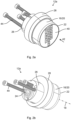
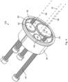
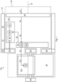
- the actuating element 16 of this example comprises a hollow cylindrical knob 20.
- the actuating element 16 further comprises a front end 22.
- the actuating device 12a of this example further comprises a lock cylinder 26.
- the locking member 24 here protrudes rearwardly from the lock cylinder 26.
- the actuating device 12a of this example further comprises a rosette 28.
- the lock cylinder 26 and the rosette 28 for part of one example of a stationary structure of the actuating device 12a.
- the actuating device 12a further comprises a ring gear 56.
- the ring gear 56 is fixed to the knob 20 and constitutes a part of the actuating element 16.
- the ring gear 56 is concentric with the actuation axis 18.
- the actuating device 12a further comprises a transfer wheel 60.
- the transfer wheel 60 may alternatively be referred to as a first wheel.
- the transfer wheel 60 is arranged inside the ring gear 56.
- the transfer wheel 60 is here a spur gear in meshing engagement with the internal profile 58.
- the actuating device 12a of this example further comprises a second wheel 62 and a third wheel 64.
- Each of the second wheel 62 and the third wheel 64 is arranged inside the ring gear 56.
- each of the second wheel 62 and the third wheel 64 is here a spur gear in meshing engagement with the internal profile 58.
- the transfer wheel 60, the second wheel 62 and the third wheel 64 provide the only support for the actuating element 16 in radial directions with respect to the actuation axis 18.
- Fig. 5 schematically represents a cross-sectional side view of the actuating device 12a.
- the ring gear 56 is fixed to a rear end (to the left in Fig. 5 ) of the knob 20.
- a diameter of the internal profile 58 is approximately 80 % of an external diameter of the knob 20.
- the locking member 24 In the disabled state of the transfer device 72a, the locking member 24 can not be rotated from the locked position to the unlocked position by means of rotation of the actuating element 16. In this example, the actuating element 16 can however be rotated for energy harvesting when the transfer device 72a adopts the disabled state. In the enabled state of the transfer device 72a, the locking member 24 can be rotated from the locked position to the unlocked position by means of rotation of the actuating element 16.
- the transfer device 72a of this example comprises an input element 74, an output element 76.
- the input element 74 is here fixed to the transfer wheel 60 and the output element 76 is here integrally formed with the locking member 24.
- the transfer device 72a further comprises an electromechanical actuator 78. By driving the actuator 78, the transfer device 72a can be switched between the disabled state and the enabled state.
- the transfer device 72a of this example comprises a coupling shaft 80 having a collar 82.
- the actuating device 12a further comprises a control system 84, here exemplified as a PCB (printed circuit board) lying in a plane transverse to the actuation axis 18.
- the control system 84 is arranged inside the actuating element 16, between the ring gear 56 and the generator 48 along the actuation axis 18.
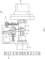
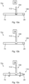
- Fig. 6 schematically represents a side view of the transfer device 72a.
- the coupling shaft 80 has a polygonal profile.
- the coupling shaft 80 is always received in the input element 74.
- the coupling shaft 80 does not engage in a corresponding polygonal opening of the output element 76.
- Rotation of the input element 74 is thereby not transmitted to a rotation of the output element 76 and the locking member 24.
- the coupling shaft 80 can be moved linearly (to the right in Fig. 6 ) into the opening of the output element 76.
- rotation of the input element 74 is transmitted by the coupling shaft 80 to a rotation of the output element 76 and the locking member 24.
- the transfer device 72a comprises a torsion spring 86 and a nut 88.
- the torsion spring 86 exerts a force on the collar 82.
- the actuator 78 can be stopped and the torsion spring 86 continues to exert a force on the coupling shaft 80 to the right.
- the torsion spring 86 forces the coupling shaft 80 into the opening.
- the transfer device 72a thereby adopts the enabled state.
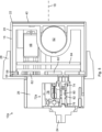
- Fig. 7 schematically represents a side view of the actuating device 12a.
- the stationary structure 90 of the actuating device 12a is shown as a volume within dashed lines.
- the stationary structure 90 is arranged partly inside the actuating element 16.
- the credential receiver 40 is here arranged entirely radially inside the knob 20 with respect to the actuation axis 18.
- an entire length of the credential receiver 40 is here arranged radially inside the knob 20 with respect to the actuation axis 18.
- the actuating element 16 When the actuating element 16 is rotated by the user, the actuating element 16 and the wheels 60, 62 and 64 rotate relative to the stationary structure 90. Rotation of the second wheel 62 drives the generator 48 to harvest electric energy. During rotation of the actuating element 16, the credential receiver 40 remains static. This provides an improved user experience and a more consistent interaction between the user and the credential receiver 40.
- the control system 84 comprises a data processing device 92 and a memory 94.
- the memory 94 has a computer program thereon.
- the computer program comprises program code which, when executed by the data processing device 92 causes the data processing device 92 to perform, or command performance of, various steps as described herein.
- the actuating device 12a comprises electrical conductors 96 connecting the control system 84 to each of the power source 46, the credential receiver 40 and the actuator 78, and an electrical conductor 96 between the power source 46 and the credential receiver 40.
- the power source 46 electrically powers the control system 84 and the credential receiver 40.
- the power source 46 here electrically powers the actuator 78 via the control system 84.
- the credential receiver 40 is configured to send an access signal 98 to the control system 84 in response to the credential input 42.
- the control system 84 is configured to evaluate the access signal 98, i.e. to determine whether the credential input 42 is valid or invalid. In case the credential input 42 is valid, the control system 84 sends an authorization signal 100 to the actuator 78 to thereby command the transfer device 72a to switch from the disabled state to the enabled state. In case the credential input 42 is invalid, the control system 84 does not issue the authorization signal 100.
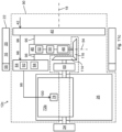
- Fig. 8 schematically represents a side view of a further example of an actuating device 12b.
- the actuating device 12b does not comprise any electric generator. Instead, the actuating device 12b is electrically powered by an external power source 46, such as a mains supply.
- an external power source 46 such as a mains supply.
- both the second wheel 62 and the third wheel 64 are support wheels for the actuating element 16.
- the actuating element 16 can be made even more compact, i.e. shorter along the actuation axis 18.
- a power source 46 comprising a battery (but no generator) may be provided in the stationary structure 90 inside the actuating element 16.
- the actuating element 16 of the actuating device 12b does not drive an electric generator, the actuating element 16 does not have to be rotated endlessly around the actuation axis 18.
- a rotation range of for example 90 degrees about the actuation axis 18 can be sufficient. In this way, more space inside the ring gear 56 can be used for the stationary structure 90.
- the actuating element 16 of the actuating device 12b when the actuating element 16 of the actuating device 12b does not drive an electric generator, the actuating element 16 can alternatively be fixed to the input element 74 of the transfer device 72a. In this way, each of the wheels 60, 62 and 64 can be omitted.
- Fig. 9a schematically represents a side view of a further example of a transfer device 72b.
- the transfer device 72b is a coupling device.
- the transfer device 72b comprises a clutch 102 controlled by the actuator 78.
- the clutch 102 is controlled by the actuator 78 to be open.
- the transfer device 72b thereby adopts a disabled state 104. In the disabled state 104, rotation of the input element 74 is not transferred to a rotation of the locking member 24.
- the locking member 24 thereby remains in a locked position 106.
- Fig. 9b schematically represents a side view of the transfer device 72b.
- the clutch 102 is controlled by the actuator 78 to be closed, e.g. in response to the authorization signal 100.
- the transfer device 72b thereby adopts an enabled state 108.
- Fig. 9c schematically represents a side view of the transfer device 72b.
- the locking member 24 can be rotated from the locked position 106 to an unlocked position 110 by rotation of the input element 74 when the transfer device 72b adopts the enabled state 108.
- Fig. 10a schematically represents a side view of a further example of a transfer device 72c. Mainly differences with respect to the transfer device 72b will be described.
- the transfer device 72c is a blocking device.
- the input element 74 is fixed to the locking member 24, here integrally formed with the locking member 24.
- the transfer device 72c comprises a blocking member 112 controlled by the actuator 78.
- the blocking member 112 is controlled by the actuator 78 to engage in a recess in the input element 74.
- the blocking member 112 blocks rotation of the input element 74 and the locking member 24.
- the transfer device 72c thereby adopts the disabled state 104.
- the actuating device 12a and 12b comprises the transfer device 72c, the actuating element 16 cannot be rotated when the transfer device 72c adopts the disabled state 104.
- Fig. 10b schematically represents a side view of the transfer device 72c.
- the blocking member 112 is controlled by the actuator 78 to be retracted from the recess in the input element 74, e.g. in response to the authorization signal 100.
- the transfer device 72c thereby adopts the enabled state 108.
- Fig. 10c schematically represents a side view of the transfer device 72c.
- the locking member 24 can be rotated from the locked position 106 to the unlocked position 110 by rotation of the input element 74 when the transfer device 72c adopts the enabled state 108.
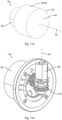
- Fig. 11a schematically represents a front perspective view of a further example of an actuating device 12c
- Fig. 11b schematically represents a partial front perspective view of the actuating device 12c
- Fig. 11c schematically represents a side view of the actuating device 12c.
- the actuating device 12c of this example comprises the transfer device 72c.
- the actuating device 12c further comprises the transfer wheel 60, but not the second wheel 62 and the third wheel 64.
- the generator 48 is here driven by the transfer wheel 60.
- the stationary structure 90 can thereby make use of more space inside the ring gear 56.
- the ring gear 56 (and the knob 20) can be made smaller in a plane transverse to the actuation axis 18.
- the first bevel gear 114 is here concentric with the transfer wheel 60.
- the second bevel gear 116 is concentric with the generator axis 54.
- a transmission (not shown) may be arranged between the transfer wheel 60 and the first bevel gear 114. Alternatively, the first bevel gear 114 may be fixed to the transfer wheel 60.
- the first bevel gear 114 lies in a plane perpendicular to the actuation axis 18 and the second bevel gear 116 lies in a plane parallel with the actuation axis 18.
- the first bevel gear 114 is larger than the second bevel gear 116.
- the first bevel gear 114 and the second bevel gear 116 thereby form a speed increasing transmission between the transfer wheel 60 and the generator 48.
Landscapes
- Physics & Mathematics (AREA)
- Electromagnetism (AREA)
- Lock And Its Accessories (AREA)
Claims (13)
- Betätigungsvorrichtung (12a, 12b, 12c) für eine Schlossvorrichtung (10), wobei die Betätigungsvorrichtung (12a, 12b, 12c) umfasst:- eine stationäre Struktur (90), die einen Berechtigungsempfänger (40) zum Empfangen einer Berechtigungseingabe (42) von einem Benutzer aufweist;- ein Betätigungselement (16), das durch direkte Manipulation durch den Benutzer in Bezug zur stationären Struktur (90) um eine Betätigungsachse (18) drehbar ist, wobei die stationäre Struktur (90) mindestens teilweise innerhalb des Betätigungselements (16) angeordnet ist;- ein Verriegelungselement (24), das zwischen einer verriegelten Position (106) und einer entriegelten Position (110) bewegbar ist; und- eine elektromechanische Übertragungsvorrichtung (72a-72c), die angeordnet ist, um basierend auf der Berechtigungseingabe (42), einen deaktivierten Zustand (104), in dem das Verriegelungselement (24) durch Drehung des Betätigungselements (16) nicht von der verriegelten Position (106) in die entriegelte Position (110) bewegt werden kann, und einen aktivierten Zustand (108) einzunehmen, in dem das Verriegelungselement (24) durch Drehung des Betätigungselements (16) von der verriegelten Position (106) in die entriegelte Position (110) bewegt werden kann;wobei der Berechtigungsempfänger (40) mindestens teilweise radial innerhalb des Betätigungselements (16) in Bezug auf die Betätigungsachse (18) angeordnet ist; wobei die Betätigungsvorrichtung (12a, 12b, 12c) weiter ein Übertragungsrad (60) umfasst, das um eine Übertragungsachse (66) parallel zu der Betätigungsachse (18) drehbar ist, wobei das Übertragungsrad (60) radial innerhalb des Betätigungselements (16) in Bezug auf die Betätigungsachse (18) positioniert ist, wobei das Übertragungsrad (60) angeordnet ist, um ein Eingabeelement (74) der Übertragungsvorrichtung (72a-72c) anzutreiben, und wobei das Betätigungselement (16) ein Innenprofil (58) umfasst, das mit dem Übertragungsrad (60) eingreift;dadurch gekennzeichnet, dass die Betätigungsvorrichtung (12a, 12b, 12c) weiter ein um eine zweite Achse (68) drehbares zweites Rad (62) und ein um eine dritte Achse (70) drehbares drittes Rad (64) umfasst, wobei jede von der zweiten Achse (68) und der dritten Achse (70) parallel zur Betätigungsachse (18) verläuft, wobei jedes von dem zweiten Rad (62) und dem dritten Rad (64) in Bezug auf die Betätigungsachse (18) radial innerhalb des Betätigungselements (16) positioniert ist, und wobei das Innenprofil (58) mit jedem von dem zweiten Rad (62) und dem dritten Rad (64) eingreift.
- Betätigungsvorrichtung (12a, 12b, 12c) nach Anspruch 1, wobei das Eingabeelement (74) drehbar ist und wobei das Übertragungsrad (60) an dem Eingabeelement (74) befestigt oder in einem Stück damit gebildet ist.
- Betätigungsvorrichtung (12a, 12b, 12c) nach einem der vorstehenden Ansprüche, wobei eines, mehrere oder alle von dem Übertragungsrad (60), dem zweiten Rad (62) und dem dritten Rad (64) ein Zahnrad ist/sind, und wobei das Innenprofil (58) eine Innenverzahnung umfasst, die mit dem einen oder mehreren Zahnrädern verzahnt ist.
- Betätigungsvorrichtung (12a, 12b, 12c) nach einem der vorstehenden Ansprüche, wobei das Betätigungselement (16) einen Knopf (20) umfasst.
- Betätigungsvorrichtung (12a, 12b, 12c) nach einem der vorstehenden Ansprüche, wobei das Betätigungselement (16) ein vorderes Ende (22) umfasst und wobei der Berechtigungsempfänger (40) im Wesentlichen mit dem vorderen Ende (22) ausgerichtet ist.
- Betätigungsvorrichtung (12a, 12b, 12c) nach einem der vorstehenden Ansprüche, die weiter ein Steuersystem (84) umfasst, das konfiguriert ist, um bei Vorlage einer gültigen Berechtigungseingabe (42) durch den Benutzer, ein Autorisierungssignal (100) an die Übertragungsvorrichtung (72a-72c) herauszugeben, und wobei das Steuersystem (84) in der stationären Struktur (90) angeordnet ist.
- Betätigungsvorrichtung (12a, 12b, 12c) nach einem der vorstehenden Ansprüche, die weiter eine Leistungsquelle (46) umfasst.
- Betätigungsvorrichtung (12a, 12b, 12c) nach Anspruch 7, wobei die Übertragungsvorrichtung (72a-72c) angeordnet ist, um von der Leistungsquelle (46) elektrisch versorgt zu werden.
- Betätigungsvorrichtung (12a, 12b, 12c) nach Anspruch 7 oder 8, wobei die Leistungsquelle (46) in der stationären Struktur (90) angeordnet ist.
- Betätigungsvorrichtung (12a, 12b, 12c) nach einem der Ansprüche 7 bis 9, wobei die Leistungsquelle (46) einen elektrischen Generator (48) umfasst, der angeordnet ist, um durch Drehung des Betätigungselements (16) angetrieben zu werden, um dadurch elektrische Leistung zu erzeugen.
- Betätigungsvorrichtung (12c) nach Anspruch 10, wenn von Anspruch 2 abhängig, wobei der Generator (48) angeordnet ist, um durch Drehung des Übertragungsrades (60) angetrieben zu werden.
- Betätigungsvorrichtung (12a, 12b, 12c) nach Anspruch 10 oder 11, wobei der Generator (48) eine Generatorachse (54) umfasst und wobei die Generatorachse (54) um 30 Grad bis 150 Grad zur Betätigungsachse (18) abgewinkelt ist.
- Schlossvorrichtung (10), die eine Betätigungsvorrichtung (12a, 12b, 12c) nach einem der vorstehenden Ansprüche umfasst.
Applications Claiming Priority (2)
| Application Number | Priority Date | Filing Date | Title |
|---|---|---|---|
| SE2150566A SE545233C2 (en) | 2021-05-04 | 2021-05-04 | Actuating device for lock device, and lock device |
| PCT/EP2022/060265 WO2022233568A1 (en) | 2021-05-04 | 2022-04-19 | Actuating device for lock device, and lock device |
Publications (2)
| Publication Number | Publication Date |
|---|---|
| EP4334552A1 EP4334552A1 (de) | 2024-03-13 |
| EP4334552B1 true EP4334552B1 (de) | 2025-03-12 |
Family
ID=81654696
Family Applications (1)
| Application Number | Title | Priority Date | Filing Date |
|---|---|---|---|
| EP22723594.2A Active EP4334552B1 (de) | 2021-05-04 | 2022-04-19 | Betätigungsvorrichtung für eine schlossvorrichtung und schlossvorrichtung |
Country Status (6)
| Country | Link |
|---|---|
| US (1) | US12467282B2 (de) |
| EP (1) | EP4334552B1 (de) |
| ES (1) | ES3020657T3 (de) |
| FI (1) | FI4334552T3 (de) |
| SE (1) | SE545233C2 (de) |
| WO (1) | WO2022233568A1 (de) |
Families Citing this family (3)
| Publication number | Priority date | Publication date | Assignee | Title |
|---|---|---|---|---|
| WO2022068481A1 (zh) * | 2020-09-30 | 2022-04-07 | 深圳市凯迪仕智能科技有限公司 | 用于门锁的驱动机构、门锁 |
| SE545233C2 (en) | 2021-05-04 | 2023-05-30 | Assa Abloy Ab | Actuating device for lock device, and lock device |
| EP4502323A1 (de) * | 2023-08-04 | 2025-02-05 | Nuki Home Solutions GmbH | Vorrichtung und verfahren zur betätigung eines schlosses |
Family Cites Families (15)
| Publication number | Priority date | Publication date | Assignee | Title |
|---|---|---|---|---|
| DE19919283A1 (de) * | 1998-06-03 | 1999-12-09 | Dom Sicherheitstechnik | Schließzylinder |
| EP0962612A3 (de) * | 1998-06-03 | 2002-10-16 | DOM Sicherheitstechnik GmbH | Schliesszylinder |
| DE19824713A1 (de) * | 1998-06-03 | 1999-12-16 | Dom Sicherheitstechnik | Schließzylinder |
| DE102004017664A1 (de) | 2004-04-05 | 2005-10-20 | Oliver Rein | Mechatronischer Schließzylinder mit manuellem Antriebselement |
| US8272240B1 (en) * | 2006-10-11 | 2012-09-25 | Schilens James A | Remote control marine lock system |
| US7908896B1 (en) * | 2006-10-23 | 2011-03-22 | Olson Timothy L | Biometric deadbolt lock assembly |
| GB0803281D0 (en) * | 2008-02-22 | 2008-04-02 | Mccormack Scott A | Locks and inserts therefor |
| EP2365475B1 (de) * | 2010-03-12 | 2013-05-08 | DESI Alarm ve Güvenlik Sistemleri Sanayi ve Ticaret Ltd. Sti. | Elektrisches Zylinderschloss |
| DK177991B1 (en) * | 2013-10-07 | 2015-02-16 | Poly Care Aps | Motorised door lock actuator |
| DK179566B1 (en) * | 2015-12-29 | 2019-02-19 | Danalock Ivs | Electromechanical door lock actuation device and method for operating it |
| CN206360487U (zh) * | 2016-12-23 | 2017-07-28 | 深圳诺托智能科技有限公司 | 一种适用于自动门锁的动力传输装置 |
| CN107905668B (zh) * | 2017-12-08 | 2023-08-29 | 泉州施米德智能科技有限公司 | 一种内嵌式智能门开关装置 |
| EP3693526B1 (de) * | 2019-02-08 | 2026-04-15 | Assa Abloy AB | Betätigungsvorrichtung für eine verriegelungsvorrichtung und verriegelungssystem mit einer solchen betätigungsvorrichtung |
| CN110017064A (zh) * | 2019-05-13 | 2019-07-16 | 安徽安思恒信息科技有限公司 | 一种电动机械门锁传动装置 |
| SE545233C2 (en) | 2021-05-04 | 2023-05-30 | Assa Abloy Ab | Actuating device for lock device, and lock device |
-
2021
- 2021-05-04 SE SE2150566A patent/SE545233C2/en unknown
-
2022
- 2022-04-19 WO PCT/EP2022/060265 patent/WO2022233568A1/en not_active Ceased
- 2022-04-19 FI FIEP22723594.2T patent/FI4334552T3/fi active
- 2022-04-19 US US18/558,585 patent/US12467282B2/en active Active
- 2022-04-19 ES ES22723594T patent/ES3020657T3/es active Active
- 2022-04-19 EP EP22723594.2A patent/EP4334552B1/de active Active
Also Published As
| Publication number | Publication date |
|---|---|
| US12467282B2 (en) | 2025-11-11 |
| SE545233C2 (en) | 2023-05-30 |
| US20240218702A1 (en) | 2024-07-04 |
| SE2150566A1 (en) | 2022-11-05 |
| FI4334552T3 (fi) | 2025-04-30 |
| ES3020657T3 (en) | 2025-05-23 |
| WO2022233568A1 (en) | 2022-11-10 |
| EP4334552A1 (de) | 2024-03-13 |
Similar Documents
| Publication | Publication Date | Title |
|---|---|---|
| EP4334552B1 (de) | Betätigungsvorrichtung für eine schlossvorrichtung und schlossvorrichtung | |
| EP4261369B1 (de) | Elektronisch betätigter schliesszylinder | |
| CA3111502C (en) | MODULAR CLUTCH MECHANISM | |
| RU2337220C2 (ru) | Цилиндровый дверной замок | |
| EP3168393B1 (de) | Anordnung für ein elektronisches verriegelungssystem und elektronisches verriegelungssystem mit der anordnung | |
| CN101918661B (zh) | 闩锁促动器和使用该闩锁促动器的闩锁 | |
| EP1402139A2 (de) | Verriegelungsvorrichtung | |
| US20180266146A1 (en) | Electric lock and clutch mechanism thereof | |
| WO2015065944A1 (en) | Electromechanical lock cylinder | |
| CN113167086B (zh) | 具有钥匙式机械优先的机电式把手锁定的凸轮锁 | |
| WO2022044025A1 (en) | Mechanical muti-point lock with an electro-mechanical unit for remote operation | |
| CN211473702U (zh) | 基于槽轮传动的智能门锁 | |
| CN112252851A (zh) | 智能锁芯 | |
| EP4263982B1 (de) | Kupplungsanordnung für eine verriegelungsvorrichtung und verriegelungsvorrichtung | |
| CN213927892U (zh) | 多功能锁芯 | |
| CN210918550U (zh) | 锁具及电动车 | |
| EP3263810B1 (de) | Verlaufsverwaltungssystem für elektronische verriegelungsvorrichtung | |
| US11555333B2 (en) | Electronic lock having dislocated transmission mechanism inside | |
| CN112796578A (zh) | 一种基于槽轮传动的智能门锁 | |
| JP7519086B2 (ja) | 電気錠 | |
| WO2025093974A1 (en) | Electronic lock cylinder including a motorized electric unit and a power and control unit | |
| EP4713553A1 (de) | Vorhängeschloss | |
| CN112282518A (zh) | 便捷锁芯 | |
| JP2020051187A (ja) | 鍵機構 | |
| KR20040004776A (ko) | 도어 잠금 장치 |
Legal Events
| Date | Code | Title | Description |
|---|---|---|---|
| STAA | Information on the status of an ep patent application or granted ep patent |
Free format text: STATUS: UNKNOWN |
|
| STAA | Information on the status of an ep patent application or granted ep patent |
Free format text: STATUS: THE INTERNATIONAL PUBLICATION HAS BEEN MADE |
|
| PUAI | Public reference made under article 153(3) epc to a published international application that has entered the european phase |
Free format text: ORIGINAL CODE: 0009012 |
|
| STAA | Information on the status of an ep patent application or granted ep patent |
Free format text: STATUS: REQUEST FOR EXAMINATION WAS MADE |
|
| 17P | Request for examination filed |
Effective date: 20231124 |
|
| AK | Designated contracting states |
Kind code of ref document: A1 Designated state(s): AL AT BE BG CH CY CZ DE DK EE ES FI FR GB GR HR HU IE IS IT LI LT LU LV MC MK MT NL NO PL PT RO RS SE SI SK SM TR |
|
| DAV | Request for validation of the european patent (deleted) | ||
| DAX | Request for extension of the european patent (deleted) | ||
| GRAP | Despatch of communication of intention to grant a patent |
Free format text: ORIGINAL CODE: EPIDOSNIGR1 |
|
| STAA | Information on the status of an ep patent application or granted ep patent |
Free format text: STATUS: GRANT OF PATENT IS INTENDED |
|
| INTG | Intention to grant announced |
Effective date: 20241212 |
|
| GRAS | Grant fee paid |
Free format text: ORIGINAL CODE: EPIDOSNIGR3 |
|
| GRAA | (expected) grant |
Free format text: ORIGINAL CODE: 0009210 |
|
| STAA | Information on the status of an ep patent application or granted ep patent |
Free format text: STATUS: THE PATENT HAS BEEN GRANTED |
|
| AK | Designated contracting states |
Kind code of ref document: B1 Designated state(s): AL AT BE BG CH CY CZ DE DK EE ES FI FR GB GR HR HU IE IS IT LI LT LU LV MC MK MT NL NO PL PT RO RS SE SI SK SM TR |
|
| REG | Reference to a national code |
Ref country code: GB Ref legal event code: FG4D |
|
| REG | Reference to a national code |
Ref country code: CH Ref legal event code: EP |
|
| REG | Reference to a national code |
Ref country code: DE Ref legal event code: R096 Ref document number: 602022011744 Country of ref document: DE |
|
| REG | Reference to a national code |
Ref country code: IE Ref legal event code: FG4D |
|
| REG | Reference to a national code |
Ref country code: FI Ref legal event code: FGE |
|
| REG | Reference to a national code |
Ref country code: ES Ref legal event code: FG2A Ref document number: 3020657 Country of ref document: ES Kind code of ref document: T3 Effective date: 20250523 |
|
| PG25 | Lapsed in a contracting state [announced via postgrant information from national office to epo] |
Ref country code: RS Free format text: LAPSE BECAUSE OF FAILURE TO SUBMIT A TRANSLATION OF THE DESCRIPTION OR TO PAY THE FEE WITHIN THE PRESCRIBED TIME-LIMIT Effective date: 20250612 |
|
| PGFP | Annual fee paid to national office [announced via postgrant information from national office to epo] |
Ref country code: FI Payment date: 20250421 Year of fee payment: 4 |
|
| PGFP | Annual fee paid to national office [announced via postgrant information from national office to epo] |
Ref country code: DE Payment date: 20250408 Year of fee payment: 4 |
|
| PGFP | Annual fee paid to national office [announced via postgrant information from national office to epo] |
Ref country code: ES Payment date: 20250509 Year of fee payment: 4 |
|
| REG | Reference to a national code |
Ref country code: LT Ref legal event code: MG9D |
|
| PG25 | Lapsed in a contracting state [announced via postgrant information from national office to epo] |
Ref country code: NO Free format text: LAPSE BECAUSE OF FAILURE TO SUBMIT A TRANSLATION OF THE DESCRIPTION OR TO PAY THE FEE WITHIN THE PRESCRIBED TIME-LIMIT Effective date: 20250612 |
|
| PG25 | Lapsed in a contracting state [announced via postgrant information from national office to epo] |
Ref country code: HR Free format text: LAPSE BECAUSE OF FAILURE TO SUBMIT A TRANSLATION OF THE DESCRIPTION OR TO PAY THE FEE WITHIN THE PRESCRIBED TIME-LIMIT Effective date: 20250312 |
|
| REG | Reference to a national code |
Ref country code: NL Ref legal event code: MP Effective date: 20250312 |
|
| PG25 | Lapsed in a contracting state [announced via postgrant information from national office to epo] |
Ref country code: LV Free format text: LAPSE BECAUSE OF FAILURE TO SUBMIT A TRANSLATION OF THE DESCRIPTION OR TO PAY THE FEE WITHIN THE PRESCRIBED TIME-LIMIT Effective date: 20250312 |
|
| PG25 | Lapsed in a contracting state [announced via postgrant information from national office to epo] |
Ref country code: BG Free format text: LAPSE BECAUSE OF FAILURE TO SUBMIT A TRANSLATION OF THE DESCRIPTION OR TO PAY THE FEE WITHIN THE PRESCRIBED TIME-LIMIT Effective date: 20250312 Ref country code: GR Free format text: LAPSE BECAUSE OF FAILURE TO SUBMIT A TRANSLATION OF THE DESCRIPTION OR TO PAY THE FEE WITHIN THE PRESCRIBED TIME-LIMIT Effective date: 20250613 |
|
| REG | Reference to a national code |
Ref country code: AT Ref legal event code: MK05 Ref document number: 1775120 Country of ref document: AT Kind code of ref document: T Effective date: 20250312 |
|
| PG25 | Lapsed in a contracting state [announced via postgrant information from national office to epo] |
Ref country code: NL Free format text: LAPSE BECAUSE OF FAILURE TO SUBMIT A TRANSLATION OF THE DESCRIPTION OR TO PAY THE FEE WITHIN THE PRESCRIBED TIME-LIMIT Effective date: 20250312 |
|
| PG25 | Lapsed in a contracting state [announced via postgrant information from national office to epo] |
Ref country code: SE Free format text: LAPSE BECAUSE OF FAILURE TO SUBMIT A TRANSLATION OF THE DESCRIPTION OR TO PAY THE FEE WITHIN THE PRESCRIBED TIME-LIMIT Effective date: 20250312 |
|
| PG25 | Lapsed in a contracting state [announced via postgrant information from national office to epo] |
Ref country code: SM Free format text: LAPSE BECAUSE OF FAILURE TO SUBMIT A TRANSLATION OF THE DESCRIPTION OR TO PAY THE FEE WITHIN THE PRESCRIBED TIME-LIMIT Effective date: 20250312 |
|
| PG25 | Lapsed in a contracting state [announced via postgrant information from national office to epo] |
Ref country code: PT Free format text: LAPSE BECAUSE OF FAILURE TO SUBMIT A TRANSLATION OF THE DESCRIPTION OR TO PAY THE FEE WITHIN THE PRESCRIBED TIME-LIMIT Effective date: 20250714 |
|
| PG25 | Lapsed in a contracting state [announced via postgrant information from national office to epo] |
Ref country code: PL Free format text: LAPSE BECAUSE OF FAILURE TO SUBMIT A TRANSLATION OF THE DESCRIPTION OR TO PAY THE FEE WITHIN THE PRESCRIBED TIME-LIMIT Effective date: 20250312 Ref country code: IT Free format text: LAPSE BECAUSE OF FAILURE TO SUBMIT A TRANSLATION OF THE DESCRIPTION OR TO PAY THE FEE WITHIN THE PRESCRIBED TIME-LIMIT Effective date: 20250312 |
|
| PG25 | Lapsed in a contracting state [announced via postgrant information from national office to epo] |
Ref country code: AT Free format text: LAPSE BECAUSE OF FAILURE TO SUBMIT A TRANSLATION OF THE DESCRIPTION OR TO PAY THE FEE WITHIN THE PRESCRIBED TIME-LIMIT Effective date: 20250312 |
|
| PG25 | Lapsed in a contracting state [announced via postgrant information from national office to epo] |
Ref country code: EE Free format text: LAPSE BECAUSE OF FAILURE TO SUBMIT A TRANSLATION OF THE DESCRIPTION OR TO PAY THE FEE WITHIN THE PRESCRIBED TIME-LIMIT Effective date: 20250312 Ref country code: CZ Free format text: LAPSE BECAUSE OF FAILURE TO SUBMIT A TRANSLATION OF THE DESCRIPTION OR TO PAY THE FEE WITHIN THE PRESCRIBED TIME-LIMIT Effective date: 20250312 |
|
| PG25 | Lapsed in a contracting state [announced via postgrant information from national office to epo] |
Ref country code: RO Free format text: LAPSE BECAUSE OF FAILURE TO SUBMIT A TRANSLATION OF THE DESCRIPTION OR TO PAY THE FEE WITHIN THE PRESCRIBED TIME-LIMIT Effective date: 20250312 |
|
| PG25 | Lapsed in a contracting state [announced via postgrant information from national office to epo] |
Ref country code: SK Free format text: LAPSE BECAUSE OF FAILURE TO SUBMIT A TRANSLATION OF THE DESCRIPTION OR TO PAY THE FEE WITHIN THE PRESCRIBED TIME-LIMIT Effective date: 20250312 |
|
| PG25 | Lapsed in a contracting state [announced via postgrant information from national office to epo] |
Ref country code: IS Free format text: LAPSE BECAUSE OF FAILURE TO SUBMIT A TRANSLATION OF THE DESCRIPTION OR TO PAY THE FEE WITHIN THE PRESCRIBED TIME-LIMIT Effective date: 20250712 |
|
| REG | Reference to a national code |
Ref country code: CH Ref legal event code: H13 Free format text: ST27 STATUS EVENT CODE: U-0-0-H10-H13 (AS PROVIDED BY THE NATIONAL OFFICE) Effective date: 20251125 |
|
| PG25 | Lapsed in a contracting state [announced via postgrant information from national office to epo] |
Ref country code: LU Free format text: LAPSE BECAUSE OF NON-PAYMENT OF DUE FEES Effective date: 20250419 |
|
| REG | Reference to a national code |
Ref country code: DE Ref legal event code: R097 Ref document number: 602022011744 Country of ref document: DE |
|
| PG25 | Lapsed in a contracting state [announced via postgrant information from national office to epo] |
Ref country code: MC Free format text: LAPSE BECAUSE OF FAILURE TO SUBMIT A TRANSLATION OF THE DESCRIPTION OR TO PAY THE FEE WITHIN THE PRESCRIBED TIME-LIMIT Effective date: 20250312 |
|
| REG | Reference to a national code |
Ref country code: BE Ref legal event code: MM Effective date: 20250430 |
|
| PG25 | Lapsed in a contracting state [announced via postgrant information from national office to epo] |
Ref country code: DK Free format text: LAPSE BECAUSE OF FAILURE TO SUBMIT A TRANSLATION OF THE DESCRIPTION OR TO PAY THE FEE WITHIN THE PRESCRIBED TIME-LIMIT Effective date: 20250312 |
|
| PG25 | Lapsed in a contracting state [announced via postgrant information from national office to epo] |
Ref country code: BE Free format text: LAPSE BECAUSE OF NON-PAYMENT OF DUE FEES Effective date: 20250430 |
|
| PLBE | No opposition filed within time limit |
Free format text: ORIGINAL CODE: 0009261 |
|
| STAA | Information on the status of an ep patent application or granted ep patent |
Free format text: STATUS: NO OPPOSITION FILED WITHIN TIME LIMIT |
|
| PG25 | Lapsed in a contracting state [announced via postgrant information from national office to epo] |
Ref country code: CH Free format text: LAPSE BECAUSE OF NON-PAYMENT OF DUE FEES Effective date: 20250430 |
|
| REG | Reference to a national code |
Ref country code: CH Ref legal event code: L10 Free format text: ST27 STATUS EVENT CODE: U-0-0-L10-L00 (AS PROVIDED BY THE NATIONAL OFFICE) Effective date: 20260121 |
|
| 26N | No opposition filed |
Effective date: 20251215 |
|
| PGFP | Annual fee paid to national office [announced via postgrant information from national office to epo] |
Ref country code: GB Payment date: 20260303 Year of fee payment: 5 |
|
| PG25 | Lapsed in a contracting state [announced via postgrant information from national office to epo] |
Ref country code: IE Free format text: LAPSE BECAUSE OF NON-PAYMENT OF DUE FEES Effective date: 20250419 |
|
| PG25 | Lapsed in a contracting state [announced via postgrant information from national office to epo] |
Ref country code: FR Free format text: LAPSE BECAUSE OF NON-PAYMENT OF DUE FEES Effective date: 20250512 |