EP4335280A1 - Dispositif de mesure d'une machine de travail agricole autopropulsée - Google Patents
Dispositif de mesure d'une machine de travail agricole autopropulsée Download PDFInfo
- Publication number
- EP4335280A1 EP4335280A1 EP23179456.1A EP23179456A EP4335280A1 EP 4335280 A1 EP4335280 A1 EP 4335280A1 EP 23179456 A EP23179456 A EP 23179456A EP 4335280 A1 EP4335280 A1 EP 4335280A1
- Authority
- EP
- European Patent Office
- Prior art keywords
- self
- agricultural machine
- propelled agricultural
- crop
- measuring device
- Prior art date
- Legal status (The legal status is an assumption and is not a legal conclusion. Google has not performed a legal analysis and makes no representation as to the accuracy of the status listed.)
- Granted
Links
Images

Classifications
-
- A—HUMAN NECESSITIES
- A01—AGRICULTURE; FORESTRY; ANIMAL HUSBANDRY; HUNTING; TRAPPING; FISHING
- A01D—HARVESTING; MOWING
- A01D41/00—Combines, i.e. harvesters or mowers combined with threshing devices
- A01D41/12—Details of combines
- A01D41/127—Control or measuring arrangements specially adapted for combines
- A01D41/1271—Control or measuring arrangements specially adapted for combines for measuring crop flow
-
- A—HUMAN NECESSITIES
- A01—AGRICULTURE; FORESTRY; ANIMAL HUSBANDRY; HUNTING; TRAPPING; FISHING
- A01D—HARVESTING; MOWING
- A01D41/00—Combines, i.e. harvesters or mowers combined with threshing devices
- A01D41/12—Details of combines
- A01D41/127—Control or measuring arrangements specially adapted for combines
- A01D41/1277—Control or measuring arrangements specially adapted for combines for measuring grain quality
Definitions
- the present invention relates to a self-propelled agricultural machine for picking up crops and for processing and conveying a stream of crops formed from the picked-up crop, and a measuring device for this self-propelled agricultural machine.
- Self-propelled agricultural machines which include combine harvesters and forage harvesters, pick up crops from the field and process them with a series of implements in order to be able to skim off the largest possible grain yield into the harvesting machine's grain tank.
- These implements can be controlled, and in particular their parameters - i.e. operating parameters of the implements - can be adjusted and, depending on the setting of these parameters and the prevailing boundary conditions, the result is a higher or lower quality of the harvested crop.
- modern harvesting machines regularly have control and regulating devices, which in turn can be operated by the driver from his driver's cab.
- these implements include the threshing mechanism, which regularly contains a threshing concave and a plurality of threshing elements as well as a cleaning device with a fan and several sieves, which is arranged downstream of the threshing mechanism in the direction of movement of the crop flow.
- a measuring arrangement for the spectroscopic examination and throughput recording of a crop stream includes a spectrometer, a light source, a window, a dispersive element and a detector, the light source illuminating and illuminating the crop flow through the window during operation
- Light reflected from the crop flow falls through the window onto the dispersive element, which deflects it onto the detector in different directions depending on the wavelength.
- the measuring arrangement has a throughput determining device with a baffle plate that interacts with the crop flow.
- the window is located in the area below the maximum curvature of the baffle plate and is firmly mounted on the baffle plate in a corresponding cutout thereof. This window protrudes into the flow area of the crop stream and disrupts the flow of the crop stream, so that, for example, undesirable turbulence arises.
- a spectrometer cannot produce a series of images of the crop flow.
- the present invention is based on the object of specifying an improved or at least an alternative embodiment of a measuring device for a self-propelled agricultural machine, in particular the positioning and/or the design of the components of the measuring device with respect to the crop flow being provided in such a way that a more compact and/or More cost-effective construction of the measuring device is made possible.
- the present invention is based on the general idea that a camera device is at least partially arranged in and/or on a baffle plate against which the stream of crop material impacts during operation of the self-propelled agricultural machine.
- the self-propelled agricultural machine according to the invention for picking up crops and for processing and conveying a stream of crops formed from the picked up crops can be designed as a combine harvester and forage harvester.
- the self-propelled agricultural machine has a measuring device for measuring the crop flow.
- the measuring device has a camera device for recording a series of images of the crop stream and a throughput measuring device for measuring the throughput of the crop stream.
- the measuring device includes a baffle plate against which the stream of crop material impacts during operation of the self-propelled agricultural machine. The position of the baffle plate depends on the throughput of the crop flow and is recorded using the throughput measuring device.
- the measuring device can be arranged at the outlet of a grain elevator of the self-propelled agricultural machine, which conveys the crop upwards from cleaning.
- the throughput measuring device for throughput measurement can be designed as a load cell, in particular as a load cell and/or as a platform load cell.
- the camera device is at least partially arranged in and/or on the baffle plate.
- This has the particular advantage that the camera device as well as the baffle plate are positioned at a point in relation to the crop flow where the crop of the crop flow is not segregated. This ensures that the crop rests against the camera device in such a way that optimal, in particular high-contrast, images of the crop can be generated and at the same time the baffle plate is positioned at the point at which a maximum of the crop of the crop stream flows and is deflected.
- the force when diverting the crop flow is the measure of the grain throughput and thus the yield.
- the throughput measuring device is connected to the baffle plate via the camera device.
- the flow measuring device is connected to the camera device while the camera device is connected to the baffle plate.
- the camera device has an optically transparent housing piece, the camera device being arranged in and/or on the baffle plate in such a way that this optically transparent housing piece, in addition to the baffle plate, forms a baffle area against which the crop flow during during the operation of the self-propelled agricultural machine.
- the baffle plate can be made of an optically non-transparent material and/or material.
- the optically transparent housing piece can be, for example, a pane, in particular a glass pane.
- the optically transparent housing piece can form a lens.
- the optically transparent housing piece can be made of a material that is sufficiently transparent to visible light. This results in a more compact and cost-effective design of the measuring device.
- the baffle plate has a curved baffle surface against which the flow of crop material bounces during operation of the self-propelled agricultural machine, with the transparent housing piece of the camera device also having a curved housing piece surface against which the flow of crop material bounces during operation of the self-propelled agricultural machine.
- the curved housing piece surface can form the transparent housing piece into a lens of the camera device.
- the curved housing piece surface and the curved impact surface are each designed to be concavely curved.
- the curved housing piece surface and the curved impact surface can each be concavely curved, viewed from the crop flow and / or from a chain wheel of a grain elevator of the self-propelled agricultural machine.
- the transparent housing piece and the baffle plate are designed in such a way, in particular shaped and/or aligned and/or positioned, that the housing piece surface is arranged neither in front nor recessed with respect to the baffle surface.
- the camera device has at least one image sensor for recording two-dimensional images of the crop flow.
- a two-dimensional image of the crop flow forms a two-dimensional image, in particular a digital two-dimensional image, of the crop flow.
- broken grains and non-grains in the crop flow can be determined.
- the measuring device for measuring the crop flow is arranged at the upper end of a grain elevator of the self-propelled agricultural machine.
- the measuring device can be arranged at the outlet of the grain elevator, in particular at the outlet of the upwardly conveying grain elevator.
- the measuring device has a moisture sensor for measuring the moisture of the crop stream.
- the moisture sensor is arranged on and/or in the baffle plate.
- the self-propelled agricultural machine has an evaluation device for determining the crop parameter "broken grain fraction" (BKA) of the crop stream and/or the crop parameter "non-grain fraction” (NKA) of the crop stream based on an image analysis of the recorded image series .
- broken grain share or “non-grain share” means the proportion of broken grains in all grains in the crop flow on the one hand and the proportion of material in the crop flow that is not grain in the sense of the crop on the other hand. Material that actually represents grain, but is not grain of the currently harvested crop, can also be included in the non-grain portion.
- This broken grain or non-grain portion can relate to the image area currently captured by the corresponding image series or to a specific, just captured partial volume of the crop flow. However, it is preferred that the broken grain portion and/or the non-grain portion is related to a throughput of the main crop stream, i.e. to the entirety of the main crop stream as it is passed through the harvester and especially the combine harvester.
- the determined fraction of broken grain and/or non-grain fraction can be based on a single image of the image series, on the entire image series or on a special selection of one or more images of the image series.
- One or more images can be selected from the image series, which represent the best image according to a quality criterion.
- a quality criterion can be a particularly suitable brightness, contour or contrast distribution.
- the evaluation device basically carries out an image analysis of the image series or a part of the image series, in which preferably first broken grains and non-grains in the image are recognized using suitable algorithms. The area occupied by the broken grains and non-grains on the two-dimensional image is then calculated as an area ratio and this area ratio is extrapolated to a volume fraction using a suitable extrapolation function.
- the invention further relates to the measuring device for a self-propelled agricultural machine, with reference being made to the previous and following explanations regarding the measuring device with regard to the design of the measuring device.
- the Fig. 1 shows a self-propelled agricultural machine 1 for picking up crop 2 and for processing and conveying a crop stream 3 formed from the picked up crop 2, the crop stream 3 being in the Fig. 2 is shown.
- a driver who is in a driver's cab 22 drives the self-propelled agricultural machine Working machine 1 through a crop stock and picks up the crop 2 with a cutting unit 24. With an inclined conveyor 25, this crop 2 is conveyed to the threshing unit, which has threshing elements 27 and threshing baskets 26.
- the crop stream reaches the separating device 33, which is designed here as a separating rotor, in which freely movable grains of the crop stream are separated into a lower area.
- the crop flow reaches a cleaning device 30 via the return floor 32, which consists of several sieve levels 31 and a blower 28, as shown here.
- a grain elevator 13 finally leads the crop flow to the grain tank 35.
- the previously listed components of the self-propelled agricultural machine 1 represent controllable working devices 29 of the self-propelled agricultural machine 1, which can be controlled and/or regulated by means of an evaluation device 14 and/or a control device 23.
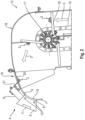
- the evaluation device 14 and/or a control device 23 can access information from a measuring device 4, which is in the Fig. 2 is shown.
- the measuring device 4 for measuring the crop flow 3 is arranged at the upper end of a grain elevator 13 of the self-propelled agricultural machine 1.
- the grain elevator 13 has a conveyor chain 15 on which conveyor elements 16 are designed to convey the crop 2, the conveyor chain 15 being driven by at least one chain wheel 17.
- the grain elevator 13 has a cover section 18 and a guide section 19 releasably attached thereto with a guide surface 20, the measuring device 4 being releasably attached to the guide section 19 by means of a holder 21.
- the measuring device 4 is arranged at the outlet of the upward conveying grain elevator 13.
- the measuring device 4 has a camera device 5 for recording a series of images of the crop stream 3 and a throughput measuring device 6 for measuring the throughput of the crop stream 3.
- the measuring device 4 includes a baffle plate 7 against which the crop stream 3 impacts during operation of the self-propelled agricultural machine 1. The position of the baffle plate 7 depends on the throughput of the crop stream 3 and is detected by the throughput measuring device 6.
- the throughput measuring device 6 for throughput measurement can be designed as a load cell, in particular as a load cell and/or as a platform load cell.
- the camera device 5 is at least partially arranged in and/or on the baffle plate 7. This has the particular advantage that the camera device 5 as well as the baffle plate 7 are positioned at a point relative to the crop stream 3 where the crop 2 of the crop stream 3 is not segregated. This ensures that the crop 2 rests against the camera device 5 in such a way that optimal, in particular high-contrast, images of the crop 2 can be generated and at the same time the baffle plate 7 is positioned at the point at which a maximum of the crop 2 of the crop stream 3 flows and is redirected.
- the force when diverting the crop 2 of the crop stream 3 is the measure of the grain throughput and thus the yield.
- the throughput measuring device 6 is connected to the baffle plate 7 via the camera device 5.
- the flow measuring device 6 is connected to the camera device 5, while the camera device 5 is connected to the baffle plate 6.
- the camera device 5 has an optically transparent housing piece 8, the camera device 5 being arranged in and/or on the baffle plate 7 in such a way that this optically transparent housing piece 8, in addition to the baffle plate 7, forms a baffle area against which the crop stream 3 is exposed during operation self-propelled agricultural machine 1 crashes.
- the optically transparent housing piece 8 can be, for example, a pane, in particular a glass pane, and can form, for example, an optical lens.
- the baffle plate 7 has a curved baffle surface 9, against which the crop stream 3 bounces during the operation of the self-propelled agricultural machine 1, the transparent housing piece 8 of the camera device also having a curved housing piece surface 10, against which the crop stream 3 during the operation of the self-propelled agricultural machine Work machine 1 crashes.
- the curved housing piece surface 10 can form the transparent housing piece 8 into a lens of the camera device 5.
- the curved housing piece surface 10 and the curved baffle surface 9 are each designed to be concavely curved.
- the curved housing piece surface 10 and the curved baffle surface 9 can be based on the crop stream 3 and/or based on viewed from the chain wheel 17 of the grain elevator 13 of the self-propelled agricultural machine 1, each be concavely curved.
- the transparent housing piece 8 and the baffle plate 7 are designed in such a way, in particular shaped and/or aligned and/or positioned, that the housing piece surface 10 is arranged neither in front nor recessed with respect to the baffle surface 9.
- Such an arrangement has the advantage that the transparent housing piece 8 of the camera device 5 can not only be arranged particularly close to the crop stream 3 and its presence influences the guidance of the crop stream 3 on the crop transport path as little as possible, but it also causes the components of the Crop stream 3 itself causes its cleaning by hitting the transparent housing piece 8. This effectively prevents dust from gathering.
- the camera device 5 has an image sensor 11 for recording two-dimensional images of the crop stream 3. Such a two-dimensional image of the crop stream 3 forms a two-dimensional image, in particular a digital two-dimensional image, of the crop stream 3. Using such a two-dimensional image, broken grains and non-grains in the crop stream 3 can be determined. Furthermore, the camera device 5 has at least one lighting device 12.
- measuring device 4 can have a moisture sensor, not shown, for measuring the moisture of the crop stream 3.
- This moisture sensor can be arranged on and/or in the baffle plate 7.
- the evaluation device 14 of the self-propelled agricultural machine 1 is designed and/or programmed to determine the crop parameter “broken grain fraction” (BKA) of the crop stream and/or the crop parameter “non-grain fraction” (NKA) of the crop stream based on an image analysis of the recorded image series.
- the determined fraction of broken grain and/or non-grain fraction can be based on a single image of the image series, on the entire image series or on a special selection of one or more images of the image series.
- One or more images can be selected from the image series, which represent the best image according to a quality criterion.
- a quality criterion can be a particularly suitable brightness, contour or contrast distribution.
- the evaluation device 14 basically carries out an image analysis of the image series or a part of the image series, in which preferably first broken grains and non-grains in the image can be recognized using suitable algorithms.
- the area occupied by the broken grains and non-grains on the two-dimensional image is then calculated as an area ratio and this area ratio is extrapolated to a volume fraction using a suitable extrapolation function.
- the control device 23 can receive evaluation data from the evaluation device 14 and/or throughput measurement values from the throughput measuring device 6 and control and/or regulate the controllable implements 29 of the self-propelled agricultural machine 1 based on these evaluation data and/or throughput measurement values.
- the control device 23 can be communicatively connected to the evaluation device 14 and/or to the measuring device 4.
- the evaluation device 14 can be connected to the measuring device 4 in a communicative manner.
Landscapes
- Life Sciences & Earth Sciences (AREA)
- Environmental Sciences (AREA)
- Investigating Materials By The Use Of Optical Means Adapted For Particular Applications (AREA)
- Combines (AREA)
Applications Claiming Priority (1)
| Application Number | Priority Date | Filing Date | Title |
|---|---|---|---|
| DE102022121838.4A DE102022121838A1 (de) | 2022-08-30 | 2022-08-30 | Messvorrichtung einer selbstfahrenden landwirtschaftlichen Arbeitsmaschine |
Publications (2)
| Publication Number | Publication Date |
|---|---|
| EP4335280A1 true EP4335280A1 (fr) | 2024-03-13 |
| EP4335280B1 EP4335280B1 (fr) | 2026-04-08 |
Family
ID=86851736
Family Applications (1)
| Application Number | Title | Priority Date | Filing Date |
|---|---|---|---|
| EP23179456.1A Active EP4335280B1 (fr) | 2022-08-30 | 2023-06-15 | Machine de travail agricole autopropulsée avec un dispositif de mesure |
Country Status (2)
| Country | Link |
|---|---|
| EP (1) | EP4335280B1 (fr) |
| DE (1) | DE102022121838A1 (fr) |
Citations (5)
| Publication number | Priority date | Publication date | Assignee | Title |
|---|---|---|---|---|
| EP1305994A1 (fr) * | 2001-10-25 | 2003-05-02 | Deere & Company | Capteur d'humidité de grain |
| EP2189781A2 (fr) | 2008-10-31 | 2010-05-26 | Deere & Company | Agencement de mesure pour l'examen spectroscopique et l'établissement d'une moyenne d'un flux de récoltes |
| EP2401906A1 (fr) * | 2010-07-01 | 2012-01-04 | CLAAS Selbstfahrende Erntemaschinen GmbH | Dispositif de détection et de détermination de la composition de matières en vrac |
| EP2826356A1 (fr) * | 2013-07-08 | 2015-01-21 | CLAAS Selbstfahrende Erntemaschinen GmbH | Moissonneuse |
| EP3301408A1 (fr) * | 2016-09-29 | 2018-04-04 | CLAAS Selbstfahrende Erntemaschinen GmbH | Système de dispositif de mesure d'un débit massique constitué de produit en vrac |
-
2022
- 2022-08-30 DE DE102022121838.4A patent/DE102022121838A1/de active Pending
-
2023
- 2023-06-15 EP EP23179456.1A patent/EP4335280B1/fr active Active
Patent Citations (5)
| Publication number | Priority date | Publication date | Assignee | Title |
|---|---|---|---|---|
| EP1305994A1 (fr) * | 2001-10-25 | 2003-05-02 | Deere & Company | Capteur d'humidité de grain |
| EP2189781A2 (fr) | 2008-10-31 | 2010-05-26 | Deere & Company | Agencement de mesure pour l'examen spectroscopique et l'établissement d'une moyenne d'un flux de récoltes |
| EP2401906A1 (fr) * | 2010-07-01 | 2012-01-04 | CLAAS Selbstfahrende Erntemaschinen GmbH | Dispositif de détection et de détermination de la composition de matières en vrac |
| EP2826356A1 (fr) * | 2013-07-08 | 2015-01-21 | CLAAS Selbstfahrende Erntemaschinen GmbH | Moissonneuse |
| EP3301408A1 (fr) * | 2016-09-29 | 2018-04-04 | CLAAS Selbstfahrende Erntemaschinen GmbH | Système de dispositif de mesure d'un débit massique constitué de produit en vrac |
Also Published As
| Publication number | Publication date |
|---|---|
| EP4335280B1 (fr) | 2026-04-08 |
| DE102022121838A1 (de) | 2024-02-29 |
Similar Documents
| Publication | Publication Date | Title |
|---|---|---|
| EP2401906B1 (fr) | Dispositif de détection et de détermination de la composition de matières en vrac | |
| DE102008043377A1 (de) | Messanordnung zur spektroskopischen Untersuchung und Durchsatzerfassung eines Erntegutstroms | |
| EP2845461B1 (fr) | Agencement de mesure de perte dans une moissonneuse-batteuse | |
| DE102008001783A1 (de) | Messanordnung zur Bestimmung der Inhaltsstoffe einer aus einem Erntegutstrom entnommenen Probe | |
| DE10130652A1 (de) | Mähdrescher mit Wurfgebläse | |
| EP1038429A1 (fr) | Dispositif pour mesurer la quantité des grains dans le dispositif de renvoi de résidus d'une moissonneuse-batteuse | |
| EP3959958A1 (fr) | Ensileuse | |
| EP4008171A1 (fr) | Procédé de fonctionnement d'une moissonneuse-batteuse | |
| EP3622800A1 (fr) | Engin d'abattage-façonnage agricole | |
| EP3959957A1 (fr) | Ensileuse | |
| DE3834102A1 (de) | Maehdrescher | |
| DE102018212075A1 (de) | Mähdrescher mit einem Schrägförderer mit aktorisch verstellbarer, unterer Umlenkwalze | |
| DE102005027741A1 (de) | Sieb für eine Reinigungseinrichtung eines Mähdreschers | |
| EP0727135A1 (fr) | Moissonneuse-batteuse | |
| EP4335280B1 (fr) | Machine de travail agricole autopropulsée avec un dispositif de mesure | |
| EP1321024B2 (fr) | Procédé et dispositif d'optimisation du fonctionnement d'un véhicule agricole | |
| EP1754407B1 (fr) | Machine de récolte agricole | |
| DE102013218618A1 (de) | Reinigungseinrichtung für einen Mähdrescher | |
| DE102007007385A1 (de) | Mähdrescher | |
| EP4268570B1 (fr) | Moissonneuse-batteuse automotrice | |
| DE102023114272A1 (de) | Selbstfahrender Mähdrescher mit einem Vorsatzgerät | |
| DE102023116408A1 (de) | Kamerasystem für einen selbstfahrenden Feldhäcksler | |
| DE102021110556A1 (de) | Mähdrescher sowie Verfahren zum Betreiben eines Mähdreschers | |
| DE102023135458A1 (de) | Selbstfahrende Erntemaschine | |
| EP4677990A1 (fr) | Moissonneuse-batteuse et procédé de fonctionnement d'une moissonneuse-batteuse |
Legal Events
| Date | Code | Title | Description |
|---|---|---|---|
| PUAI | Public reference made under article 153(3) epc to a published international application that has entered the european phase |
Free format text: ORIGINAL CODE: 0009012 |
|
| STAA | Information on the status of an ep patent application or granted ep patent |
Free format text: STATUS: THE APPLICATION HAS BEEN PUBLISHED |
|
| AK | Designated contracting states |
Kind code of ref document: A1 Designated state(s): AL AT BE BG CH CY CZ DE DK EE ES FI FR GB GR HR HU IE IS IT LI LT LU LV MC ME MK MT NL NO PL PT RO RS SE SI SK SM TR |
|
| P01 | Opt-out of the competence of the unified patent court (upc) registered |
Effective date: 20240313 |
|
| STAA | Information on the status of an ep patent application or granted ep patent |
Free format text: STATUS: REQUEST FOR EXAMINATION WAS MADE |
|
| 17P | Request for examination filed |
Effective date: 20240913 |
|
| RBV | Designated contracting states (corrected) |
Designated state(s): AL AT BE BG CH CY CZ DE DK EE ES FI FR GB GR HR HU IE IS IT LI LT LU LV MC ME MK MT NL NO PL PT RO RS SE SI SK SM TR |
|
| GRAP | Despatch of communication of intention to grant a patent |
Free format text: ORIGINAL CODE: EPIDOSNIGR1 |
|
| STAA | Information on the status of an ep patent application or granted ep patent |
Free format text: STATUS: GRANT OF PATENT IS INTENDED |
|
| RIC1 | Information provided on ipc code assigned before grant |
Ipc: A01D 41/127 20060101AFI20251030BHEP |
|
| INTG | Intention to grant announced |
Effective date: 20251114 |
|
| GRAS | Grant fee paid |
Free format text: ORIGINAL CODE: EPIDOSNIGR3 |
|
| GRAA | (expected) grant |
Free format text: ORIGINAL CODE: 0009210 |
|
| STAA | Information on the status of an ep patent application or granted ep patent |
Free format text: STATUS: THE PATENT HAS BEEN GRANTED |
|
| AK | Designated contracting states |
Kind code of ref document: B1 Designated state(s): AL AT BE BG CH CY CZ DE DK EE ES FI FR GB GR HR HU IE IS IT LI LT LU LV MC ME MK MT NL NO PL PT RO RS SE SI SK SM TR |
|
| REG | Reference to a national code |
Ref country code: CH Ref legal event code: F10 Free format text: ST27 STATUS EVENT CODE: U-0-0-F10-F00 (AS PROVIDED BY THE NATIONAL OFFICE) Effective date: 20260408 Ref country code: GB Ref legal event code: FG4D Free format text: NOT ENGLISH |
|
| REG | Reference to a national code |
Ref country code: DE Ref legal event code: R096 Ref document number: 502023003646 Country of ref document: DE |