EP4335550A1 - Broyeur avec un carter en plusieurs parties - Google Patents
Broyeur avec un carter en plusieurs parties Download PDFInfo
- Publication number
- EP4335550A1 EP4335550A1 EP23192948.0A EP23192948A EP4335550A1 EP 4335550 A1 EP4335550 A1 EP 4335550A1 EP 23192948 A EP23192948 A EP 23192948A EP 4335550 A1 EP4335550 A1 EP 4335550A1
- Authority
- EP
- European Patent Office
- Prior art keywords
- cutting
- housing
- drive shaft
- product
- longitudinal axis
- Prior art date
- Legal status (The legal status is an assumption and is not a legal conclusion. Google has not performed a legal analysis and makes no representation as to the accuracy of the status listed.)
- Withdrawn
Links
- 239000012530 fluid Substances 0.000 claims description 77
- 239000007788 liquid Substances 0.000 claims description 14
- 238000007789 sealing Methods 0.000 claims description 5
- 238000007599 discharging Methods 0.000 claims description 2
- 238000013459 approach Methods 0.000 claims 1
- 239000000047 product Substances 0.000 description 97
- 239000007789 gas Substances 0.000 description 17
- 238000007872 degassing Methods 0.000 description 5
- 238000001816 cooling Methods 0.000 description 4
- 238000006073 displacement reaction Methods 0.000 description 4
- QVGXLLKOCUKJST-UHFFFAOYSA-N atomic oxygen Chemical compound [O] QVGXLLKOCUKJST-UHFFFAOYSA-N 0.000 description 3
- 238000004140 cleaning Methods 0.000 description 3
- 239000001301 oxygen Substances 0.000 description 3
- 229910052760 oxygen Inorganic materials 0.000 description 3
- 230000002349 favourable effect Effects 0.000 description 2
- 235000013372 meat Nutrition 0.000 description 2
- 238000000034 method Methods 0.000 description 2
- 239000002245 particle Substances 0.000 description 2
- 230000008092 positive effect Effects 0.000 description 2
- 239000000126 substance Substances 0.000 description 2
- 241000251468 Actinopterygii Species 0.000 description 1
- 241000283690 Bos taurus Species 0.000 description 1
- 241001465754 Metazoa Species 0.000 description 1
- 238000009825 accumulation Methods 0.000 description 1
- 230000009286 beneficial effect Effects 0.000 description 1
- 230000015572 biosynthetic process Effects 0.000 description 1
- 210000000988 bone and bone Anatomy 0.000 description 1
- 239000006227 byproduct Substances 0.000 description 1
- 230000006866 deterioration Effects 0.000 description 1
- 230000000694 effects Effects 0.000 description 1
- 238000000605 extraction Methods 0.000 description 1
- 239000006260 foam Substances 0.000 description 1
- 235000013305 food Nutrition 0.000 description 1
- 239000002994 raw material Substances 0.000 description 1
- 235000013580 sausages Nutrition 0.000 description 1
- 238000000926 separation method Methods 0.000 description 1
- 230000011664 signaling Effects 0.000 description 1
- 238000011144 upstream manufacturing Methods 0.000 description 1
- 235000013311 vegetables Nutrition 0.000 description 1
Images


Classifications
-
- B—PERFORMING OPERATIONS; TRANSPORTING
- B02—CRUSHING, PULVERISING, OR DISINTEGRATING; PREPARATORY TREATMENT OF GRAIN FOR MILLING
- B02C—CRUSHING, PULVERISING, OR DISINTEGRATING IN GENERAL; MILLING GRAIN
- B02C18/00—Disintegrating by knives or other cutting or tearing members which chop material into fragments
- B02C18/30—Mincing machines with perforated discs and feeding worms
- B02C18/301—Mincing machines with perforated discs and feeding worms with horizontal axis
- B02C18/304—Mincing machines with perforated discs and feeding worms with horizontal axis with several axially aligned knife-perforated disc units
-
- B—PERFORMING OPERATIONS; TRANSPORTING
- B02—CRUSHING, PULVERISING, OR DISINTEGRATING; PREPARATORY TREATMENT OF GRAIN FOR MILLING
- B02C—CRUSHING, PULVERISING, OR DISINTEGRATING IN GENERAL; MILLING GRAIN
- B02C18/00—Disintegrating by knives or other cutting or tearing members which chop material into fragments
- B02C18/30—Mincing machines with perforated discs and feeding worms
- B02C18/305—Details
- B02C2018/307—Cooling arrangements in mincing machines
Definitions
- the present invention relates to a shredding machine for shredding a product, comprising: a cutting device for shredding the product, which has at least two cutting sets, a drive shaft for driving the cutting sets, and a housing in which the cutting sets are arranged one behind the other along a longitudinal axis of the drive shaft.
- Such a shredding machine is, for example, from EP 2 987 557 B1 known.
- the shredding machine has a cutting set housing in which several cutting sets or a cutting set with several cutting stages is accommodated. Different types of cutting sets can be inserted into the cutting set housing, for example cutting sets in which stationary perforated plates interact with rotating cutting heads, cutting sets in which stationary perforated plates interact with rotating perforated plates, cutting sets that are based on the rotor-stator principle, etc.
- a shredding machine that has a closed machine stand in which a 3-, 5- or 7-piece cutting set can be arranged is offered by Seydelmann Maschinenfabrik KG under the product name Konti-Kutter KK 140 AC-6 (see " www.seydelmann.com/wpcontent/uploads/2015/2017150529-_-Datenblatt-KK-140-DE. pdf").
- the product that is shredded in the shredding machine can in principle be any product to be shredded.
- the product to be shredded can be a food product or a product from the chemical industry.
- the cutting sets When assembling such a shredding machine for shredding a specific product, the cutting sets are inserted one after the other along the longitudinal axis of the drive shaft through an opening in the housing. During dismantling or cleaning, the cutting sets or their components are pulled out of the housing through the opening. This can cause the components to tilt. Removal can also be made difficult by product residue remaining in the housing. Cleaning such a housing when it is arranged horizontally and stationary is also more difficult.
- a shredding machine of the type mentioned at the outset in which the housing has at least two, preferably at least three housing parts, in each of which at least one of the cutting sets is accommodated, the housing parts preferably abutting against one another in a sealing manner along the longitudinal axis of the drive shaft.
- the housing in which the cutting sets are arranged or accommodated consists of at least two, preferably at least three, four, five or more housing parts, i.e. the housing parts are not accommodated in a larger, one-piece housing.
- the cutting sets are not accommodated in a one-piece, closed housing as in conventional shredding machines, but in a housing that has several (at least two) housing parts.
- the multi-part, modular structure of the housing of the shredding machine according to the invention makes its handling much easier: When assembling the shredding machine, the housing parts with the cutting sets can be pushed together one after the other. The housing parts in which the cutting sets are housed can be pulled apart just as easily during disassembly or cleaning.
- the modular design also allows the length of the housing to be changed in the direction of the longitudinal axis of the drive shaft: the number of housing parts or cutting sets used to shred the product can therefore be easily adjusted depending on the type of product to be shredded be adjusted.
- the housing parts can have a substantially annular geometry, but this is not absolutely necessary.
- the housing parts lie against each other in a sealing manner along the longitudinal axis of the drive shaft.
- the housing parts lie directly against one another and are connected to the
- the shredding device has a clamping device for clamping the at least two housing parts along the longitudinal axis of the drive shaft.
- the tensioning device can be designed hydraulically or mechanically. As described above, the housing parts are pushed onto the drive shaft during assembly and brought into contact with one another. In order to ensure that the housing parts fit together in a sealing manner even under pressure, it is typically necessary to brace them in the longitudinal direction of the drive shaft, i.e. to press them against each other in the longitudinal direction of the drive shaft. There are various options for bracing the housing parts.
- the clamping device is designed to be hydraulic, it typically has at least one hydraulic cylinder for applying the clamping pressure.
- the hydraulic cylinder can be a double-acting cylinder, the piston rod of which can be extended with the help of a hydraulic fluid in order to press the housing parts against one another in the longitudinal direction of the drive shaft and to brace them.
- At least one of the housing parts has at least one guide element for cooperation with a linear guide, in particular a guide rod, for guidance along the longitudinal axis of the drive shaft during assembly and disassembly.
- a linear guide in particular a guide rod
- the housing parts can be moved along linear guides, for example along one or more guide rods, guide rails or guide profiles, when they are plugged onto the drive shaft.
- the tensioning device can engage the linear guides in order to clamp the housing parts along the longitudinal axis of the drive shaft, which corresponds to the direction of the linear guides.
- the guide element can, for example, have an opening extending along the longitudinal axis of the drive shaft, into which the linear guide, for example
- the opening(s) for engagement of the linear guide(s) can be formed on projections which protrude in the radial direction beyond the outer circumference of the, for example, annular housing parts.
- the linear guides it is also possible for the linear guides to be designed in the form of guide grooves or the like, in which the housing parts are guided along the longitudinal axis of the drive shaft.
- one of the housing parts in which a cutting set is accommodated forms an outlet housing for discharging the shredded product.
- the cutting set is typically accommodated or attached to the front end of the outlet housing in the conveying direction of the product.
- An ejector can be arranged in the outlet housing. The ejector serves to centrifugally accelerate the shredded product before the shredded product is discharged from the shredding machine via an outlet, for example in the form of an outlet nozzle.
- Linear guides e.g. in the form of guide rods, can be attached to the outlet housing.
- the outlet housing is not displaceable relative to the guide rods along the longitudinal direction of the drive shaft, but rather fixes the guide rods along the longitudinal axis of the drive shaft.
- the outlet housing can also be mounted so that it can move along the linear guide.
- the linear guides e.g. the guide rods, are attached to the housing part that is closest to the drive unit (motor) of the shredder, which drives the drive shaft.
- the shredding machine comprises an inlet housing for feeding a product to be shredded to the cutting device.
- the inlet housing can also have at least one guide element for cooperation with a linear guide, in particular with a guide rod of a guide profile, etc., for guidance along the longitudinal axis of the drive shaft.
- the inlet housing like the housing parts, which each accommodate a cutting set, can be moved along the linear guide and clamped together with the housing parts along the longitudinal axis of the drive shaft.
- the cutting set is typically arranged at the rear end of the inlet housing in the conveying direction of the product.
- the inlet housing can also serve to supply a fluid, for example a gas, to the supplied product, as described in more detail below.
- At least one cutting set has a stationary perforated plate which interacts with a rotating cutting head to shred the product. It is possible for all cutting sets of the shredding machine to have a stationary perforated plate and a rotating cutting head, but this is not mandatory.
- the cutting set(s) of the shredding machine can also be designed in a different way, for example a cutting set based on the rotor-stator principle can be used.
- the rotor of such a cutting set is typically arranged radially on the inside and surrounded by the annular stator located radially on the outside.
- the rotor has knife blades which interact with cutting gaps in the stator or with holes in the stator (perforated drum) to shred the product in the manner of a scissor cut.
- the cutting heads of at least two cutting sets have a different diameter and/or the perforated plates of at least two cutting sets have a different diameter.
- the diameters of the perforated plates are also the same size in this case.
- this rule is deviated from, ie two or more cutting sets are used to shred the product, the cutting head diameter and/or the perforated plate diameter of which differ from one another.
- the diameters of the cutting heads and/or the diameters of the perforated plates increase in the conveying direction of the product. It has proven to be advantageous if the cutting head diameter of the cutting heads increases in the conveying direction of the product, since the product is shredded more and more in the conveying direction.
- the cutting speed also increases, so that with the help of the different diameters of the cutting heads or the perforated plates, the cutting stages can have different cutting speeds at the same speed.
- the increase in the diameter of the perforated plates can also have a positive effect with smaller diameters of the holes in the perforated plates and “harder particles” present in the product.
- a distance between the cutting head and the stationary perforated plate is preferably adjustable in the longitudinal direction or along the longitudinal axis of the drive shaft.
- the stationary perforated plate and/or the cutting head can be moved in the axial direction.
- the displacement of the stationary perforated plate in the axial direction can take place, for example, in that an adjusting body, against which the stationary perforated plate of the cutting set is brought into contact, is displaced in the axial direction within the housing part, while the drive shaft with the cutting head remains stationary in the axial direction.
- the adjusting body can, for example, be designed as a sleeve which is rotatably mounted with an external thread in a corresponding internal thread of the housing part.
- the drive shaft is mounted so that it can move in the longitudinal direction.
- the axial displacement of the drive shaft can also take place during the rotational movement of the drive shaft.
- the distance over which the axial distance can be varied is usually a few millimeters.
- At least one cutting set has a stationary perforated plate, which is connected to a rotating perforated plate for shredding the Product interacts.
- a cutting set With such a cutting set, the product is smashed and squashed rather than cut and therefore appears creamier than is the case when shredded using a cutting set in which a cutting head interacts with a stationary perforated plate.
- the shredding machine is designed to supply a fluid, in particular a liquid gas, into at least one intermediate space which is formed in the housing between two cutting sets adjacent along the longitudinal axis of the drive shaft.
- a fluid i.e. a liquid or a gas
- a fluid is introduced directly into the product between two adjacent cutting sets or cutting stages. It has been shown that the supply of a liquid or a gas is also possible in a closed system, i.e. between two axially, i.e. along the longitudinal axis of the drive shaft, adjacent cutting sets, without this causing critical pressures that lead to a deterioration of the quality of the product or damage to the shredding machine. This also applies in the event that the drive shaft, which is driven by a motor, rotates at high speeds of more than, for example, 3000 revolutions/min.
- the fluid can be used, for example, to inert, that is, to increase the shelf life by displacing atmospheric oxygen and/or to control the temperature, for example to cool, the product.
- a liquid gas for example liquid N 2 or CO 2
- the product is cooled directly at the location where heat is generated by the shredding of the product using a respective cutting set.
- the cooling is therefore particularly efficient; In addition, only a small portion of the energy used for cooling is released into the environment.
- the addition of gases or liquid gases to the product also has the advantage that they are removed from the product without leaving any residue when the product leaves the shredding machine, whereas this is the case when adding liquids is not the case.
- the degassing of the product can be carried out in the outlet area.
- the degassing of the product (“deareation”) can also be carried out using a degassing system.
- An effective degassing or suction system (degasser or deaerator) can be designed, for example, in the form of a hollow cylinder similar to a cyclone. On the input side of such an extraction system, a large surface can be created using a “baffle plate”. In this way, the “head” in the cylinder can be used well for degassing.
- the gas can also remain bound in the product, for example to "foam" the product and to improve the conveying behavior of the cutting device in certain shredding processes or products to be shredded.
- a gaseous medium can be advantageous, for example, if the product tends to stick or clump, as is the case with certain products from the chemical industry.
- a feed container upstream of the cutting device can be placed under vacuum so that the vacuum-packed product is fed to the cutting device.
- a fluid, in particular a gas, is then supplied to the vacuum-packed product in the cutting device. In this way, the oxygen present in the product is exchanged by the supplied fluid or gas in a two-stage process.
- the fluid can be supplied to each of the gaps.
- the fluid it is also possible for the fluid to be supplied to only one of the gaps or two or more, but not all of the gaps. There are various options for supplying the fluid to a respective intermediate space.
- the shredding machine has at least one nozzle for exiting the fluid into the intermediate space, which is formed at one end of a feed channel, which preferably runs in a housing part of the housing.
- the nozzle influences the flow of the fluid when it passes over or when Exit from the feed channel into the gap.
- the feed channel is usually formed in one of the housing parts that accommodate a respective cutting set.
- the feed channel can be formed on another component of the shredding machine.
- the feed channel can run in or along the drive shaft and possibly in components connected to the drive shaft in a rotationally fixed manner.
- One or more nozzles or supply channels for a fluid can also be formed on the inlet housing in order to supply a fluid to the product to be shredded in the conveying direction in front of the first cutting set.
- the feed channel runs in the housing part, it typically has a first end that opens into the gap at the nozzle, and a second end that opens on the outside of the housing part.
- the supply channel is usually connected to a supply line for the fluid.
- the feed channel is preferably a single, for example radial, bore in the housing part. It is also possible for a supply channel to branch out from the second end on the outside of the housing part and to have a plurality of ends at which nozzles are formed which open into the intermediate space. There is a risk of product entering the nozzles and clogging them.
- the nozzle more precisely the inside of the nozzle, can have a constant cross section, but it is also possible for the nozzle cross section to increase or decrease in the direction of the outlet opening of the nozzle.
- the inside of the nozzle can be conical, for example.
- the nozzle can be designed to exit the fluid essentially tangentially with respect to the longitudinal axis of the drive shaft. It has proven to be advantageous if the fluid flows essentially tangentially into the gap. Substantially tangential is understood to mean that the nozzle or its longitudinal axis is in an angular range between approximately 50° and approximately 130°, preferably between approximately 70° and approximately 110°, to the radial direction in relation to the longitudinal axis of the drive shaft is aligned.
- the nozzle can be designed or aligned to allow the fluid to emerge in a plane perpendicular to the longitudinal axis of the drive shaft, but it is also possible for the longitudinal axis of the nozzle not to run in a plane perpendicular to the longitudinal axis of the drive shaft, but rather to be inclined to this plane is aligned.
- the nozzle may be oriented at a (non-zero) angle with respect to a plane perpendicular to the longitudinal axis of the drive shaft.
- the angle can, for example, be between approximately 10° and approximately 50°.
- the alignment at an angle with respect to the plane perpendicular to the drive shaft is particularly favorable if one of the cutting sets has a rotating cutting head. In this case, the angle is typically chosen so that the nozzle is inclined towards the rotating cutting head.
- the nozzle can be designed to exit the fluid in the direction of rotation of the drive shaft (during the comminution of the product). It is advantageous if the direction of flow of the fluid as it exits the nozzle approximately corresponds to the direction of flow of the product at the location of the nozzle. In particular, the fluid flowing out of the nozzle should have the same direction of rotation (clockwise or counterclockwise) as the drive shaft.
- the nozzle is formed in a projection of the housing part, which projects into the intermediate space, the projection preferably running radially in the direction of the longitudinal axis of the drive shaft.
- the projection can, for example, be designed in the manner of a finger or the like, which tapers in the radial direction towards the longitudinal axis of the drive shaft.
- the task of such a projection is to jam the product against rotation.
- the accumulation increases the conveying behavior of the cutting set and reduces the temperature input.
- the projections or jam fingers typically form part of the cutting device anyway and, due to their geometry, are particularly well suited for the introduction of the fluid into the product.
- the nozzle is preferably located in a direction facing away from the direction of rotation of the drive shaft side of the projection ("leeward side").
- Such an arrangement of the nozzle has proven to be advantageous for entraining the fluid emerging from the nozzle through the product. This applies in particular if one of the cutting sets has a cutting head that is arranged in the intermediate space or projects into it. In this case, a negative pressure is generated on the back of a respective rotating cutting knife or knife wing of the cutting head, which promotes the entrainment of the fluid emerging from the nozzle when the fluid exits on the leeward side of the projection.
- the nozzle is arranged at a radial distance from the longitudinal axis of the drive shaft, which is less than 80%, preferably less than 60%, particularly preferably less than 40% of a maximum radius of the gap between two adjacent cutting sets.
- the maximum radius of the gap is understood to mean a maximum extent of the gap in the radial direction starting from the longitudinal axis of the drive shaft.
- the nozzle Due to components protruding into the gap or due to the radial extent of the drive shaft, it is generally not possible to arrange the nozzle directly in the vicinity of the longitudinal axis of the drive shaft. However, arranging the nozzle at a distance that is less than 80%, possibly less than 60% or less than 40% of the maximum radius of the gap in the housing part is generally possible and usually sufficient so that the pressure generated by the rotation of the product is less than the pressure of the fluid exiting the nozzle.
- the shredding machine preferably has at least two nozzles for exiting the fluid into the intermediate space.
- the fluid is supplied via more than one nozzle, for example via two, three, four or more nozzles.
- the nozzles are arranged evenly distributed over the gap in the circumferential direction, that is, if they are at the same distance from one another in the circumferential direction. It is generally also advantageous if the fluid that is supplied to the intermediate space exits at the same pressure at each nozzle.
- the shredding machine preferably comprises at least one controllable valve for the controlled supply of the fluid into the intermediate space.
- the valve has an open and a closed switching state in order to release or block the supply of the fluid.
- the shredding machine has a control device, for example in the form of a control computer, which also takes over the control of other functions of the shredding machine.
- the fluid is usually provided to the controllable valve at a predetermined, constant pressure using a fluid supply.
- the fluid is advantageously supplied to a respective nozzle via a feed channel using its own controllable valve assigned to the nozzle.
- the cross section of the feed channel is usually larger than the outlet cross section of the outlet opening of the nozzle.
- the fluid can be supplied to all nozzles that are assigned to an intermediate space via a common controllable valve, or for the fluid to be supplied to all nozzles of the shredding machine via a single switchable valve.
- the shredding machine has additional components that are not described above.
- an ejector mounted on the drive shaft and driven by it is typically attached.
- the ejector serves to centrifugally accelerate the product before it is conveyed out of the shredding machine through an outlet or an outlet housing.
- the promotion of the Product can be supported by suction from the outlet side.
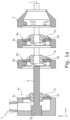
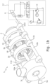
- Fig. 1a , b and Fig. 2a , b show a shredding machine 1, which has an inlet housing 2 for feeding a product to be shredded, for example meat (roast meat), raw materials of plant or animal origin (fish, vegetables), bones, boiled sausage, rinds, ....
- the inlet housing 2 is followed downstream in the conveying direction of the product by a housing 3, in which a cutting device 4 is accommodated, which is mounted on a horizontally mounted shaft 5 (drive shaft) driven by a motor 5a.
- the cutting device 4 is used to (finely) shred the product.
- the motor 5a can also be attached to the inlet end of the drive shaft 5 or to the inlet housing 2.
- the housing 3 has three housing parts 3a-c, in each of which a cutting set 4a-c of the cutting device 4 is accommodated.
- a first housing part 3a in the conveying direction of the product has a first cutting set 4a, which has a first perforated disk 6a and a first cutting head 7a, which cooperates with the first perforated disk 6a to shred the product.
- the first cutting head 7a protrudes into the inlet housing 2.
- the first housing part 3a of the housing 3 has a circular cylindrical shape on its outside and is essentially disk-shaped.
- a second housing part 3b adjoins the first housing part 3a in the conveying direction of the product or along a longitudinal axis L of the drive shaft 5.
- the second housing part 3b accommodates a second cutting set 4b.
- the third housing part 3c which accommodates a third cutting set 4c, forms an outlet housing to discharge the shredded product.
- the third housing part 3c in the form of the outlet housing has an outlet connection 8 in order to discharge the product from the third housing part 3c or from the shredding machine 1.
- the first, second and third perforated disks 6a, 6b, 6c are stationary, ie they are attached to the first, second and third housing part 3a, 3b, 3c and rotate not with the drive shaft 5.
- the first, second and third cutting heads 7a, 7b, 7c are mounted in a rotationally fixed manner via a form fit, in the example shown with the aid of grooves attached to the drive shaft 5, and are driven by it.
- a respective cutting head 7a, 7b, 7c exerts a centrifugal force on the product, so that accumulated foreign bodies in particular are carried outwards in the radial direction, where they can be removed via a separation valve.
- the cutting device 4 is completed by an ejector, not shown, which is mounted on the drive shaft 5 and which is arranged in the third housing part 3c in the form of the outlet housing.
- the ejector serves to centrifugally accelerate the shredded product before it is removed from the shredding machine 1 via the outlet housing 3c.
- the housing 3, in which the cutting device 4 or the cutting sets 4a-c are arranged is constructed in several parts, in contrast to conventional (fine) shredding machines.
- the second housing part 3b, the first housing part 3a and the inlet housing 2 are pushed onto the drive shaft 5 from the free end of the drive shaft 5 along its longitudinal axis L until the three housing parts 3a, 3b, 3c and the inlet housing 2 abut one another in a sealing manner along the longitudinal axis L, as shown in Fig. 2a ,b is shown.
- additional seals between the three housing parts 3a, 3b, 3c have not been shown.
- the shredding machine 1 has two linear guides in the form of two guide rods 10a, 10b, which extend along the longitudinal axis L of the shredding machine 1.
- the two guide rods 10a, 10b are rigidly connected to the third housing part 3c and engage in two guide elements 11a, 11b, which are designed in the form of projections.
- the guide elements 11a, 11b are formed on two diametrically opposite sides of the three housing parts 3a-c and the inlet housing 2.
- the guide elements 11a, b in shape of the projections protrude radially beyond the essentially cylindrical outer sides of the three housing parts 3a-c and the inlet housing 2 and each have an opening which extends in the direction of the longitudinal axis L of the drive shaft 5.
- One of the two guide rods 10a, b is inserted through the opening of a respective guide element 11a, b.
- the housing 3, in which the cutting sets 4a-c are accommodated, consists of the in Fig. 1a , b and Fig. 2a , b shown shredding machine 1 from the three housing parts 3a-c.
- the shredding machine 1 therefore has no additional housing in which the three housing parts 3a-c are encapsulated.
- the shredding machine 1 has a clamping device 12.
- the clamping device 12 clamps the three housing parts 3a-c, each of which has a cutting set 4a-c, and the inlet housing 2 along the longitudinal axis L of the drive shaft 5 in order to seal them and prevent the product from escaping from the multi-part housing 3.
- the tensioning device 12 can be designed hydraulically or mechanically. In the latter case, the clamping device 12 can comprise, for example, a thread or an electric cylinder or a toggle lever.
- FIG. 1b An example of a hydraulic tensioning device 12 is in Fig. 1b shown.
- the tensioning device 12 has a double-acting hydraulic cylinder 9, the piston rod of which is displaceable in the direction of the longitudinal axis L of the drive shaft 5 in order to clamp the three housing parts 3a-c, ie to press them together in the direction of the longitudinal axis L of the drive shaft 5.
- the piston rod of the hydraulic cylinder 9 pulls the three housing parts 3a-c together and presses them against the inlet housing 2, which in this case is arranged in a stationary manner.
- the hydraulic cylinder 9 it is possible for the hydraulic cylinder 9 to be on the in Fig.
- the third housing part 3c can also be arranged in a stationary manner and the hydraulic cylinder 9 can be designed to press the first and second housing parts 3a, 3b as well as the inlet housing 2 in the direction of the stationary third housing part 3c and thereby push them together when it is as shown in Fig. 1b shown on the right side of the two guide rods 10a, 10b is arranged.
- the hydraulic cylinder 9 it is possible for the hydraulic cylinder 9 to be on the in Fig. 1b Left side of the two guide rods 10a, 10b is arranged and the piston rod pulls the first housing part 3a, the second housing part 3b and the inlet housing 2 together and presses them against the third, stationary housing part 3c.
- the clamping device 12 has a hydraulic circuit with several hydraulic components.
- the supply and removal of a hydraulic fluid to or from the two chambers of the hydraulic cylinder 9 is controlled using a valve V.
- the valve V has a first switching position, which is used to move the piston rod in the direction of the three housing parts 3a-c in order to brace them in the longitudinal direction L of the drive shaft 5.
- a second switching position the supply and removal of the hydraulic fluid to and from the hydraulic cylinder 9 is blocked in order to fix the piston rod in a predetermined position in the direction of the longitudinal axis L of the drive shaft 5.
- a third switching position of the valve V is used to move the piston rod in the direction of the longitudinal axis L of the drive shaft 5 away from the three housing parts 3a-c in order to release the tension.
- the hydraulic circuit of the clamping device 12 has a hydraulic pump H, which is driven by an electric motor M.
- the hydraulic pump H delivers the hydraulic fluid from a fluid container and supplies it to the valve V along a first hydraulic line.
- a pressure gauge and a pressure limiter valve With the help of a pressure gauge and a pressure limiter valve, the pressure in the first hydraulic line is limited or adjusted.
- a second hydraulic line is used to return the hydraulic fluid from the hydraulic cylinder 9 into the fluid container.
- a controllable check valve is arranged in the hydraulic circuit between the hydraulic cylinder 9 and the valve V, which serves to protect against the escape of hydraulic fluid.
- the axial distance A - shown as an example for the first cutting set 4a - between the front of the respective stationary perforated plate 6a, 6b, 6c and the cutting head 7a, 7b, 7c which interacts with it to shred the product can be adjusted within certain limits , because in this way the The degree of comminution of the product as well as the throughput and heat input into the product can be influenced. It can also be advantageous if the respective cutting head 7a, 7b, 7c, more precisely its knife blades, can be brought into contact with the associated stationary perforated plate 6a, 6b, 6c during the rotational movement in order to re-sharpen them if necessary. For the purposes mentioned, a maximum variation of the distance A of a few millimeters, usually only one or several tenths of a millimeter, is sufficient.
- the drive shaft 5 is displaced in the axial direction or along its longitudinal axis L.
- the axial displacement of the drive shaft 5 can be carried out, for example, by means of a handwheel or by means of a control device, even during operation of the shredding machine 1, in order to set the desired distance A between the respective stationary perforated plate 6a, 6b, 6c and the associated cutting head 7a, 7b, 7c.
- the distance A can also be achieved by displacing the perforated plates 6a, 6b, 6c relative to the housing 3, more precisely to a respective housing part 3a-c, and to a drive shaft that is stationary in the axial direction, as is the case for example in the DE 199 60 409 A1 is described.
- each of the housing parts 3a-c accommodates exactly one cutting set 4a-c, in which a stationary and a rotating component work together to shred the product.
- a housing part 3a-c it is also possible for a housing part 3a-c to accommodate two or more cutting sets 4a-c.
- the cutting device 4 or the cutting sets 4a-c are not accommodated in a one-piece housing, but rather at least two of the cutting sets 4a-c are accommodated in at least two different housing parts 3a-c.
- the housing 3 can be dimensioned larger or smaller in the axial direction than in Fig. 1a , b and in Fig. 2a , b is shown.
- Fig. 3 shows a shredding machine 1, which differs from that in Fig. 1a , b and Fig. 2a , b
- the shredding machine 1 shown essentially differs in that each of the three cutting sets 4a-c each has a perforated plate 6a-c, which differ from one another in diameter D1, D2, D3, and that each of the three cutting sets 4a-c each has a cutting head 7a- c, which differ from each other in diameter d1, d2, d3.
- Both the diameters D1, D2, D3 of the perforated plates 6a-c and the diameters d1, d2, d3 of the cutting heads 7a-c increase in the conveying direction of the product, ie as the product becomes increasingly finely chopped.
- FIG. 4a -c show three different types of first cutting sets 4a, which are accommodated in a first housing part 3a, but which can of course also be used as a second or third cutting set 4b, 4c in a corresponding second or third housing part 3b, 3c of the shredding machine 1.
- Fig. 4a shows a first housing part 3a with a first cutting set 4a, which is like that in Fig. 2a or in Fig. 3 cutting sets 4a shown and which has a stationary perforated plate 6a and a rotating cutting head 7a, which work together to shred the product.
- Fig. 4b shows a first housing part 3a with a first cutting set 4a, which has a stationary perforated plate 6a, which cooperates with a rotating perforated plate 14a for shredding the product, as for example in the one cited at the beginning EP 2 987 557 B1 is described.
- the rotating perforated plate 14a is shown in Fig. 4b largely covered by the stationary perforated plate 6a.
- Cutting set 4a the product is smashed and squashed rather than cut and therefore appears creamier than is the case when shredded using a cutting set 4a, in which a cutting head 7a interacts with a stationary perforated plate 6a, as shown in Fig. 4a is the case, or as is the case with a cutting set that has a centrifugal cutting ring (rotor-stator principle).
- the one in Fig. 4c First housing part 3a shown has a cutting set 4a, in which, as in Fig. 4a Cutting set 4a shown, a stationary perforated plate 6a interact with a cutting head 7a to shred the product.
- the in Fig. 4c Housing part 3a shown makes it possible to have a first gap 13a (cf. Fig. 2a ) to supply a fluid between the first cutting set 4a and the second cutting set 4b, as described in more detail below.
- An identical second housing part 3b makes it possible to supply a fluid to a second intermediate space 13b, which is formed in the second housing part 3b.
- the first and second gaps 13a, 13b extend along the longitudinal axis L of the drive shaft 5 between the two facing sides of the stationary perforated plates 6a, 6b or 6b, 6c.
- the second and third cutting heads 7b, 7c protrude into the respective gap 13a, 13b.
- the shredding machine 1 is designed to supply a fluid to both the first gap 13a and the second gap 13b.
- the housing 3 more precisely in the in Fig. 4c shown first housing part 3a and in the correspondingly designed second housing part 3b a plurality of, for example, five supply channels 14 for the fluid are formed, which extend from a radially outer side of the housing part 3a, 3b into the respective intermediate space 13a, 13b.
- a respective feed channel 14 has a section in the form of a radial bore which tapers in the radial direction towards the longitudinal axis L of the drive shaft 5 and to which there is a section in the tangential direction in relation to the longitudinal axis L of the drive shaft 5 running section, also designed as a bore, which forms a nozzle 15 for the essentially tangential exit of the fluid into the intermediate space 11b.
- a respective nozzle 15 is designed or aligned to allow the fluid to exit into the intermediate space 13a in the same direction of rotation as the drive shaft 5.
- the nozzle 15 or its outlet opening does not run in the XZ plane, but is inclined towards the second cutting head 7b.
- the nozzle 15, which forms the tangentially extending section of the feed channel 14, and a radially inner part of the radially extending section of the feed channel 14 are formed in a projection 16 of the first housing part 3a, which is in the first gap 13a projects in the radial direction.
- the projection 16 is designed like a finger and tapers in the direction of the longitudinal axis L of the drive shaft 5.
- the provision of the projections 16 on the housing part 3a or 3b is favorable for the following reason:
- the fluid should, if possible, be supplied to the product at a location where the pressure or . the force of the fluid as it exits the respective nozzle 15 is greater than the centrifugal force exerted on the product by the cutting head 7b or 7c. Since the centrifugal force increases with increasing distance from the longitudinal axis L of the drive shaft 5, the The fluid is supplied near the longitudinal axis L of the drive shaft 5.
- a respective nozzle 15, more precisely its outlet opening is arranged at a radial distance R from the longitudinal axis L of the drive shaft 5, which is less than 80% of a maximum radius R M of the first or second gap 13a, 13b in the Housing 3 is located.
- the distance R between the nozzle 15 and the longitudinal axis L of the drive shaft can also be less than 60% or possibly less than 40% of the maximum radius R M of the respective gap 13a, 13b.
- the nozzle 15 is formed on a side of a respective projection 16 facing away from the direction of rotation of the drive shaft 5.
- the respective nozzle 15 or its outlet opening is therefore on the leeward side. In this way, when the fluid exits the nozzle 15, it can be used that a reduced pressure is generated on the back of a respective cutting blade of the cutting head 7b compared to the front of the cutting blade and the fluid is taken along when it exits the nozzle 15.
- the shredding machine 1 shown as an example has five nozzles 15, which are arranged evenly distributed in the circumferential direction or are arranged at equal distances from one another in the circumferential direction. In this way, the fluid can be supplied homogeneously to the respective intermediate space 13a, 13b. It goes without saying that more or fewer than five nozzles 15 can also be provided in order to supply the fluid to the intermediate space 13a, 13b. Due to the fact that the projections 16 on which the nozzles 15 are formed protrude in the radial direction into the respective gap 13a, 13b.
- the comminution device 1 can have a controllable valve, which is in signaling connection with a control device in order to supply the fluid - depending on the switching state of the valve - to the first or second gap 13a, 13b to enable or prevent.
- the fluid is removed from a fluid reservoir and fed to the controllable valve via a supply line.
- the reservoir can be, for example, a compressed gas bottle.
- the fluid is fed to the second to fifth nozzle 15 via additional valves, also not shown in the picture.
- Further controllable valves are used to control the supply of fluid to the nozzles which are formed in the second housing part 3b and which open into the second intermediate space 13b. It goes without saying that the assignment of the nozzles 15 to the controllable valve or valves can also be done in another way.
- the respective gap 13a, 13b does not necessarily have to be supplied with a fluid in the form of a liquid gas for cooling the product.
- a gas can also be supplied to a respective gap 13a, 13b, which can serve, for example, to inert the product or which can support the conveying effect of the cutting device 4 if the product tends to stick or lump, or a liquid, for example, to add a dye or the like to the product, or steam to heat the product.
- a fluid can also be supplied to the product in the inlet housing 2 by acting on corresponding projections 16 (cf. e.g Fig. 1b ) a nozzle 15 is attached.
Landscapes
- Engineering & Computer Science (AREA)
- Food Science & Technology (AREA)
- Crushing And Pulverization Processes (AREA)
Applications Claiming Priority (1)
| Application Number | Priority Date | Filing Date | Title |
|---|---|---|---|
| DE102022122711.1A DE102022122711B3 (de) | 2022-09-07 | 2022-09-07 | Zerkleinerungsmaschine mit einem mehrteiligen Gehäuse |
Publications (1)
| Publication Number | Publication Date |
|---|---|
| EP4335550A1 true EP4335550A1 (fr) | 2024-03-13 |
Family
ID=87762489
Family Applications (1)
| Application Number | Title | Priority Date | Filing Date |
|---|---|---|---|
| EP23192948.0A Withdrawn EP4335550A1 (fr) | 2022-09-07 | 2023-08-23 | Broyeur avec un carter en plusieurs parties |
Country Status (2)
| Country | Link |
|---|---|
| EP (1) | EP4335550A1 (fr) |
| DE (1) | DE102022122711B3 (fr) |
Citations (5)
| Publication number | Priority date | Publication date | Assignee | Title |
|---|---|---|---|---|
| DE814262C (de) * | 1944-10-25 | 1951-09-20 | Martin Michael Peter Jorgensen | Fleischwolf |
| DE29910128U1 (de) * | 1998-06-17 | 1999-08-12 | Bacher, Helmut, St. Florian | Einwellenzerkleinerer, z.B. für Kunststoff oder Holz |
| DE19960409A1 (de) | 1999-12-15 | 2001-06-21 | Inotec Gmbh Maschinenentwicklu | Vorrichtung zum Zerkleinern eines Zerkleinerungsgutes |
| DE10237220C1 (de) * | 2002-08-14 | 2003-11-27 | Oliver Haack | Kassetten-Schneidsatz |
| EP2987557B1 (fr) | 2014-08-22 | 2017-05-03 | Karl Schnell GmbH & Co. KG | Machine de broyage d'un produit |
Family Cites Families (3)
| Publication number | Priority date | Publication date | Assignee | Title |
|---|---|---|---|---|
| DE603536C (de) * | 1933-03-22 | 1934-10-08 | Josef Scholtes | Vorrichtung zum Schneiden von Nahrungsmitteln, insbesondere Fleisch |
| AT504854B1 (de) * | 2007-02-15 | 2012-08-15 | Erema | Verfahren und vorrichtung zur aufbereitung eines materials |
| DE102012005394A1 (de) | 2012-03-14 | 2013-09-19 | Inofex Fleisch-, Lebensmitteltechnik Und -Technologie Gmbh | "Zwischenlager-Schneidsatz für Zerkleinerungsmaschinen, insbesondere Fleischwölfe" |
-
2022
- 2022-09-07 DE DE102022122711.1A patent/DE102022122711B3/de active Active
-
2023
- 2023-08-23 EP EP23192948.0A patent/EP4335550A1/fr not_active Withdrawn
Patent Citations (5)
| Publication number | Priority date | Publication date | Assignee | Title |
|---|---|---|---|---|
| DE814262C (de) * | 1944-10-25 | 1951-09-20 | Martin Michael Peter Jorgensen | Fleischwolf |
| DE29910128U1 (de) * | 1998-06-17 | 1999-08-12 | Bacher, Helmut, St. Florian | Einwellenzerkleinerer, z.B. für Kunststoff oder Holz |
| DE19960409A1 (de) | 1999-12-15 | 2001-06-21 | Inotec Gmbh Maschinenentwicklu | Vorrichtung zum Zerkleinern eines Zerkleinerungsgutes |
| DE10237220C1 (de) * | 2002-08-14 | 2003-11-27 | Oliver Haack | Kassetten-Schneidsatz |
| EP2987557B1 (fr) | 2014-08-22 | 2017-05-03 | Karl Schnell GmbH & Co. KG | Machine de broyage d'un produit |
Also Published As
| Publication number | Publication date |
|---|---|
| DE102022122711B3 (de) | 2024-03-07 |
Similar Documents
| Publication | Publication Date | Title |
|---|---|---|
| DE2600648C2 (de) | Pelletpresse | |
| DE69524814T2 (de) | Kontinuierlicher Mischer und Apparat zum Entfernen von Rotorsegmenten für diesen Mischer | |
| EP2987557B1 (fr) | Machine de broyage d'un produit | |
| EP3019276A1 (fr) | Broyeur à boulets à agitateur, muni de canaux axiaux | |
| EP0813908B1 (fr) | Système de coupe et/ou de support pour hachoirs de produits alimentaires | |
| DE3208973C2 (de) | Vorrichtung zum Bearbeiten von viskosen Stoffen bzw. Stoffen, die bei der Bearbeitung viskos werden | |
| EP1237656B1 (fr) | Dispositif de broyage d'un materiau a broyer | |
| EP4286056A1 (fr) | Dispositif de broyage pour broyer un milieu contenant des matières solides et procédé de commande d'un dispositif de broyage | |
| EP3711862A1 (fr) | Dispositif de coupe, séparateur, procédé de séparation des ingrédients alimentaires au moyen d'un séparateur | |
| EP1364713A2 (fr) | Broyeur a lames pour le broyage de matière plastique et procédé d'operation correspondant | |
| EP2683487B1 (fr) | Broyeur à billes agité | |
| EP0743148A2 (fr) | Dispositif et procédé pour changement automatique de couteaux en forme de couronne sur des machines à broyer, en particulier pour couronnes à trancher pour déchiqueteur à bois | |
| DE19508093A1 (de) | Fleischwolf | |
| DE102008049339A1 (de) | Vorrichtung zum Bearbeiten von Aufgabegut | |
| EP2251085A2 (fr) | Dispositif de traitement de matériaux de chargement à l'aide d'un système rotor-stator | |
| DE102022122711B3 (de) | Zerkleinerungsmaschine mit einem mehrteiligen Gehäuse | |
| WO2024052124A1 (fr) | Machine de broyage et procédé de broyage d'un produit tout en alimentant un fluide | |
| DE10026825C2 (de) | Zerkleinerungsvorrichtung | |
| EP0637497A1 (fr) | Soudeuse pour matières thermoplastiques | |
| EP0253139B1 (fr) | Mélangeur de type rotor-stator | |
| WO2004089588A1 (fr) | Unite d'entrainement pour un granulateur | |
| EP3020974B1 (fr) | Systeme de transport de milieux visqueux, procede de fonctionnement d'un tel systeme et unite de transport correspondante | |
| CH415334A (de) | Zerkleinerungsmaschine für Fleisch oder andere zerkleinerungsfähige Nahrungsmittel und Genussmittel | |
| EP1606055B1 (fr) | Procede pour separer et evacuer des matieres premieres | |
| EP1021247B1 (fr) | Hachoir |
Legal Events
| Date | Code | Title | Description |
|---|---|---|---|
| PUAI | Public reference made under article 153(3) epc to a published international application that has entered the european phase |
Free format text: ORIGINAL CODE: 0009012 |
|
| STAA | Information on the status of an ep patent application or granted ep patent |
Free format text: STATUS: THE APPLICATION HAS BEEN PUBLISHED |
|
| AK | Designated contracting states |
Kind code of ref document: A1 Designated state(s): AL AT BE BG CH CY CZ DE DK EE ES FI FR GB GR HR HU IE IS IT LI LT LU LV MC ME MK MT NL NO PL PT RO RS SE SI SK SM TR |
|
| STAA | Information on the status of an ep patent application or granted ep patent |
Free format text: STATUS: THE APPLICATION IS DEEMED TO BE WITHDRAWN |
|
| 18D | Application deemed to be withdrawn |
Effective date: 20240914 |