EP4335573A1 - Fabrication adaptative utilisant des données de lumière structurée - Google Patents
Fabrication adaptative utilisant des données de lumière structurée Download PDFInfo
- Publication number
- EP4335573A1 EP4335573A1 EP23196313.3A EP23196313A EP4335573A1 EP 4335573 A1 EP4335573 A1 EP 4335573A1 EP 23196313 A EP23196313 A EP 23196313A EP 4335573 A1 EP4335573 A1 EP 4335573A1
- Authority
- EP
- European Patent Office
- Prior art keywords
- substrate
- braze
- data
- powder
- sintered
- Prior art date
- Legal status (The legal status is an assumption and is not a legal conclusion. Google has not performed a legal analysis and makes no representation as to the accuracy of the status listed.)
- Pending
Links
Images

Classifications
-
- B—PERFORMING OPERATIONS; TRANSPORTING
- B23—MACHINE TOOLS; METAL-WORKING NOT OTHERWISE PROVIDED FOR
- B23K—SOLDERING OR UNSOLDERING; WELDING; CLADDING OR PLATING BY SOLDERING OR WELDING; CUTTING BY APPLYING HEAT LOCALLY, e.g. FLAME CUTTING; WORKING BY LASER BEAM
- B23K35/00—Rods, electrodes, materials, or media, for use in soldering, welding, or cutting
- B23K35/02—Rods, electrodes, materials, or media, for use in soldering, welding, or cutting characterised by mechanical features, e.g. shape
- B23K35/0222—Rods, electrodes, materials, or media, for use in soldering, welding, or cutting characterised by mechanical features, e.g. shape for use in soldering or brazing
- B23K35/0244—Powders, particles or spheres; Preforms made therefrom
-
- B—PERFORMING OPERATIONS; TRANSPORTING
- B29—WORKING OF PLASTICS; WORKING OF SUBSTANCES IN A PLASTIC STATE IN GENERAL
- B29C—SHAPING OR JOINING OF PLASTICS; SHAPING OF MATERIAL IN A PLASTIC STATE, NOT OTHERWISE PROVIDED FOR; AFTER-TREATMENT OF THE SHAPED PRODUCTS, e.g. REPAIRING
- B29C64/00—Additive manufacturing, i.e. manufacturing of three-dimensional [3D] objects by additive deposition, additive agglomeration or additive layering, e.g. by 3D printing, stereolithography or selective laser sintering
- B29C64/30—Auxiliary operations or equipment
- B29C64/386—Data acquisition or data processing for additive manufacturing
- B29C64/393—Data acquisition or data processing for additive manufacturing for controlling or regulating additive manufacturing processes
-
- B—PERFORMING OPERATIONS; TRANSPORTING
- B22—CASTING; POWDER METALLURGY
- B22F—WORKING METALLIC POWDER; MANUFACTURE OF ARTICLES FROM METALLIC POWDER; MAKING METALLIC POWDER; APPARATUS OR DEVICES SPECIALLY ADAPTED FOR METALLIC POWDER
- B22F10/00—Additive manufacturing of workpieces or articles from metallic powder
- B22F10/20—Direct sintering or melting
- B22F10/25—Direct deposition of metal particles, e.g. direct metal deposition [DMD] or laser engineered net shaping [LENS]
-
- B—PERFORMING OPERATIONS; TRANSPORTING
- B22—CASTING; POWDER METALLURGY
- B22F—WORKING METALLIC POWDER; MANUFACTURE OF ARTICLES FROM METALLIC POWDER; MAKING METALLIC POWDER; APPARATUS OR DEVICES SPECIALLY ADAPTED FOR METALLIC POWDER
- B22F10/00—Additive manufacturing of workpieces or articles from metallic powder
- B22F10/60—Treatment of workpieces or articles after build-up
- B22F10/64—Treatment of workpieces or articles after build-up by thermal means
-
- B—PERFORMING OPERATIONS; TRANSPORTING
- B22—CASTING; POWDER METALLURGY
- B22F—WORKING METALLIC POWDER; MANUFACTURE OF ARTICLES FROM METALLIC POWDER; MAKING METALLIC POWDER; APPARATUS OR DEVICES SPECIALLY ADAPTED FOR METALLIC POWDER
- B22F3/00—Manufacture of workpieces or articles from metallic powder characterised by the manner of compacting or sintering; Apparatus specially adapted therefor ; Presses and furnaces
- B22F3/24—After-treatment of workpieces or articles
-
- B—PERFORMING OPERATIONS; TRANSPORTING
- B22—CASTING; POWDER METALLURGY
- B22F—WORKING METALLIC POWDER; MANUFACTURE OF ARTICLES FROM METALLIC POWDER; MAKING METALLIC POWDER; APPARATUS OR DEVICES SPECIALLY ADAPTED FOR METALLIC POWDER
- B22F7/00—Manufacture of composite layers, workpieces, or articles, comprising metallic powder, by sintering the powder, with or without compacting wherein at least one part is obtained by sintering or compression
- B22F7/06—Manufacture of composite layers, workpieces, or articles, comprising metallic powder, by sintering the powder, with or without compacting wherein at least one part is obtained by sintering or compression of composite workpieces or articles from parts, e.g. to form tipped tools
-
- B—PERFORMING OPERATIONS; TRANSPORTING
- B23—MACHINE TOOLS; METAL-WORKING NOT OTHERWISE PROVIDED FOR
- B23K—SOLDERING OR UNSOLDERING; WELDING; CLADDING OR PLATING BY SOLDERING OR WELDING; CUTTING BY APPLYING HEAT LOCALLY, e.g. FLAME CUTTING; WORKING BY LASER BEAM
- B23K1/00—Soldering, e.g. brazing, or unsoldering
- B23K1/0008—Soldering, e.g. brazing, or unsoldering specially adapted for particular articles or work
- B23K1/0018—Brazing of turbine parts
-
- B—PERFORMING OPERATIONS; TRANSPORTING
- B23—MACHINE TOOLS; METAL-WORKING NOT OTHERWISE PROVIDED FOR
- B23K—SOLDERING OR UNSOLDERING; WELDING; CLADDING OR PLATING BY SOLDERING OR WELDING; CUTTING BY APPLYING HEAT LOCALLY, e.g. FLAME CUTTING; WORKING BY LASER BEAM
- B23K1/00—Soldering, e.g. brazing, or unsoldering
- B23K1/005—Soldering by means of radiant energy
- B23K1/0056—Soldering by means of radiant energy soldering by means of beams, e.g. lasers, electron beams [EB]
-
- B—PERFORMING OPERATIONS; TRANSPORTING
- B23—MACHINE TOOLS; METAL-WORKING NOT OTHERWISE PROVIDED FOR
- B23K—SOLDERING OR UNSOLDERING; WELDING; CLADDING OR PLATING BY SOLDERING OR WELDING; CUTTING BY APPLYING HEAT LOCALLY, e.g. FLAME CUTTING; WORKING BY LASER BEAM
- B23K1/00—Soldering, e.g. brazing, or unsoldering
- B23K1/008—Soldering within a furnace
-
- B—PERFORMING OPERATIONS; TRANSPORTING
- B23—MACHINE TOOLS; METAL-WORKING NOT OTHERWISE PROVIDED FOR
- B23K—SOLDERING OR UNSOLDERING; WELDING; CLADDING OR PLATING BY SOLDERING OR WELDING; CUTTING BY APPLYING HEAT LOCALLY, e.g. FLAME CUTTING; WORKING BY LASER BEAM
- B23K1/00—Soldering, e.g. brazing, or unsoldering
- B23K1/20—Preliminary treatment of work or areas to be soldered, e.g. in respect of a galvanic coating
-
- B—PERFORMING OPERATIONS; TRANSPORTING
- B23—MACHINE TOOLS; METAL-WORKING NOT OTHERWISE PROVIDED FOR
- B23K—SOLDERING OR UNSOLDERING; WELDING; CLADDING OR PLATING BY SOLDERING OR WELDING; CUTTING BY APPLYING HEAT LOCALLY, e.g. FLAME CUTTING; WORKING BY LASER BEAM
- B23K26/00—Working by laser beam, e.g. welding, cutting or boring
- B23K26/0093—Working by laser beam, e.g. welding, cutting or boring combined with mechanical machining or metal-working covered by other subclasses than B23K
-
- B—PERFORMING OPERATIONS; TRANSPORTING
- B23—MACHINE TOOLS; METAL-WORKING NOT OTHERWISE PROVIDED FOR
- B23K—SOLDERING OR UNSOLDERING; WELDING; CLADDING OR PLATING BY SOLDERING OR WELDING; CUTTING BY APPLYING HEAT LOCALLY, e.g. FLAME CUTTING; WORKING BY LASER BEAM
- B23K26/00—Working by laser beam, e.g. welding, cutting or boring
- B23K26/02—Positioning or observing the workpiece, e.g. with respect to the point of impact; Aligning, aiming or focusing the laser beam
- B23K26/03—Observing, e.g. monitoring, the workpiece
- B23K26/032—Observing, e.g. monitoring, the workpiece using optical means
-
- B—PERFORMING OPERATIONS; TRANSPORTING
- B23—MACHINE TOOLS; METAL-WORKING NOT OTHERWISE PROVIDED FOR
- B23P—METAL-WORKING NOT OTHERWISE PROVIDED FOR; COMBINED OPERATIONS; UNIVERSAL MACHINE TOOLS
- B23P6/00—Restoring or reconditioning objects
- B23P6/002—Repairing turbine components, e.g. moving or stationary blades, rotors
- B23P6/007—Repairing turbine components, e.g. moving or stationary blades, rotors using only additive methods, e.g. build-up welding
-
- B—PERFORMING OPERATIONS; TRANSPORTING
- B29—WORKING OF PLASTICS; WORKING OF SUBSTANCES IN A PLASTIC STATE IN GENERAL
- B29C—SHAPING OR JOINING OF PLASTICS; SHAPING OF MATERIAL IN A PLASTIC STATE, NOT OTHERWISE PROVIDED FOR; AFTER-TREATMENT OF THE SHAPED PRODUCTS, e.g. REPAIRING
- B29C64/00—Additive manufacturing, i.e. manufacturing of three-dimensional [3D] objects by additive deposition, additive agglomeration or additive layering, e.g. by 3D printing, stereolithography or selective laser sintering
- B29C64/10—Processes of additive manufacturing
- B29C64/141—Processes of additive manufacturing using only solid materials
- B29C64/153—Processes of additive manufacturing using only solid materials using layers of powder being selectively joined, e.g. by selective laser sintering or melting
-
- B—PERFORMING OPERATIONS; TRANSPORTING
- B29—WORKING OF PLASTICS; WORKING OF SUBSTANCES IN A PLASTIC STATE IN GENERAL
- B29C—SHAPING OR JOINING OF PLASTICS; SHAPING OF MATERIAL IN A PLASTIC STATE, NOT OTHERWISE PROVIDED FOR; AFTER-TREATMENT OF THE SHAPED PRODUCTS, e.g. REPAIRING
- B29C64/00—Additive manufacturing, i.e. manufacturing of three-dimensional [3D] objects by additive deposition, additive agglomeration or additive layering, e.g. by 3D printing, stereolithography or selective laser sintering
- B29C64/20—Apparatus for additive manufacturing; Details thereof or accessories therefor
- B29C64/205—Means for applying layers
- B29C64/209—Heads; Nozzles
-
- B—PERFORMING OPERATIONS; TRANSPORTING
- B33—ADDITIVE MANUFACTURING TECHNOLOGY
- B33Y—ADDITIVE MANUFACTURING, i.e. MANUFACTURING OF THREE-DIMENSIONAL [3D] OBJECTS BY ADDITIVE DEPOSITION, ADDITIVE AGGLOMERATION OR ADDITIVE LAYERING, e.g. BY 3D PRINTING, STEREOLITHOGRAPHY OR SELECTIVE LASER SINTERING
- B33Y10/00—Processes of additive manufacturing
-
- B—PERFORMING OPERATIONS; TRANSPORTING
- B33—ADDITIVE MANUFACTURING TECHNOLOGY
- B33Y—ADDITIVE MANUFACTURING, i.e. MANUFACTURING OF THREE-DIMENSIONAL [3D] OBJECTS BY ADDITIVE DEPOSITION, ADDITIVE AGGLOMERATION OR ADDITIVE LAYERING, e.g. BY 3D PRINTING, STEREOLITHOGRAPHY OR SELECTIVE LASER SINTERING
- B33Y40/00—Auxiliary operations or equipment, e.g. for material handling
- B33Y40/10—Pre-treatment
-
- B—PERFORMING OPERATIONS; TRANSPORTING
- B33—ADDITIVE MANUFACTURING TECHNOLOGY
- B33Y—ADDITIVE MANUFACTURING, i.e. MANUFACTURING OF THREE-DIMENSIONAL [3D] OBJECTS BY ADDITIVE DEPOSITION, ADDITIVE AGGLOMERATION OR ADDITIVE LAYERING, e.g. BY 3D PRINTING, STEREOLITHOGRAPHY OR SELECTIVE LASER SINTERING
- B33Y40/00—Auxiliary operations or equipment, e.g. for material handling
- B33Y40/20—Post-treatment, e.g. curing, coating or polishing
-
- B—PERFORMING OPERATIONS; TRANSPORTING
- B33—ADDITIVE MANUFACTURING TECHNOLOGY
- B33Y—ADDITIVE MANUFACTURING, i.e. MANUFACTURING OF THREE-DIMENSIONAL [3D] OBJECTS BY ADDITIVE DEPOSITION, ADDITIVE AGGLOMERATION OR ADDITIVE LAYERING, e.g. BY 3D PRINTING, STEREOLITHOGRAPHY OR SELECTIVE LASER SINTERING
- B33Y50/00—Data acquisition or data processing for additive manufacturing
- B33Y50/02—Data acquisition or data processing for additive manufacturing for controlling or regulating additive manufacturing processes
-
- F—MECHANICAL ENGINEERING; LIGHTING; HEATING; WEAPONS; BLASTING
- F01—MACHINES OR ENGINES IN GENERAL; ENGINE PLANTS IN GENERAL; STEAM ENGINES
- F01D—NON-POSITIVE DISPLACEMENT MACHINES OR ENGINES, e.g. STEAM TURBINES
- F01D5/00—Blades; Blade-carrying members; Heating, heat-insulating, cooling or antivibration means on the blades or the members
- F01D5/005—Repairing methods or devices
-
- B—PERFORMING OPERATIONS; TRANSPORTING
- B22—CASTING; POWDER METALLURGY
- B22F—WORKING METALLIC POWDER; MANUFACTURE OF ARTICLES FROM METALLIC POWDER; MAKING METALLIC POWDER; APPARATUS OR DEVICES SPECIALLY ADAPTED FOR METALLIC POWDER
- B22F3/00—Manufacture of workpieces or articles from metallic powder characterised by the manner of compacting or sintering; Apparatus specially adapted therefor ; Presses and furnaces
- B22F3/24—After-treatment of workpieces or articles
- B22F2003/247—Removing material: carving, cleaning, grinding, hobbing, honing, lapping, polishing, milling, shaving, skiving, turning the surface
-
- B—PERFORMING OPERATIONS; TRANSPORTING
- B22—CASTING; POWDER METALLURGY
- B22F—WORKING METALLIC POWDER; MANUFACTURE OF ARTICLES FROM METALLIC POWDER; MAKING METALLIC POWDER; APPARATUS OR DEVICES SPECIALLY ADAPTED FOR METALLIC POWDER
- B22F7/00—Manufacture of composite layers, workpieces, or articles, comprising metallic powder, by sintering the powder, with or without compacting wherein at least one part is obtained by sintering or compression
- B22F7/06—Manufacture of composite layers, workpieces, or articles, comprising metallic powder, by sintering the powder, with or without compacting wherein at least one part is obtained by sintering or compression of composite workpieces or articles from parts, e.g. to form tipped tools
- B22F7/062—Manufacture of composite layers, workpieces, or articles, comprising metallic powder, by sintering the powder, with or without compacting wherein at least one part is obtained by sintering or compression of composite workpieces or articles from parts, e.g. to form tipped tools involving the connection or repairing of preformed parts
- B22F2007/068—Manufacture of composite layers, workpieces, or articles, comprising metallic powder, by sintering the powder, with or without compacting wherein at least one part is obtained by sintering or compression of composite workpieces or articles from parts, e.g. to form tipped tools involving the connection or repairing of preformed parts repairing articles
-
- B—PERFORMING OPERATIONS; TRANSPORTING
- B23—MACHINE TOOLS; METAL-WORKING NOT OTHERWISE PROVIDED FOR
- B23K—SOLDERING OR UNSOLDERING; WELDING; CLADDING OR PLATING BY SOLDERING OR WELDING; CUTTING BY APPLYING HEAT LOCALLY, e.g. FLAME CUTTING; WORKING BY LASER BEAM
- B23K2101/00—Articles made by soldering, welding or cutting
- B23K2101/001—Turbines
-
- F—MECHANICAL ENGINEERING; LIGHTING; HEATING; WEAPONS; BLASTING
- F05—INDEXING SCHEMES RELATING TO ENGINES OR PUMPS IN VARIOUS SUBCLASSES OF CLASSES F01-F04
- F05D—INDEXING SCHEME FOR ASPECTS RELATING TO NON-POSITIVE-DISPLACEMENT MACHINES OR ENGINES, GAS-TURBINES OR JET-PROPULSION PLANTS
- F05D2230/00—Manufacture
- F05D2230/20—Manufacture essentially without removing material
- F05D2230/23—Manufacture essentially without removing material by permanently joining parts together
- F05D2230/232—Manufacture essentially without removing material by permanently joining parts together by welding
- F05D2230/233—Electron beam welding
-
- F—MECHANICAL ENGINEERING; LIGHTING; HEATING; WEAPONS; BLASTING
- F05—INDEXING SCHEMES RELATING TO ENGINES OR PUMPS IN VARIOUS SUBCLASSES OF CLASSES F01-F04
- F05D—INDEXING SCHEME FOR ASPECTS RELATING TO NON-POSITIVE-DISPLACEMENT MACHINES OR ENGINES, GAS-TURBINES OR JET-PROPULSION PLANTS
- F05D2230/00—Manufacture
- F05D2230/20—Manufacture essentially without removing material
- F05D2230/23—Manufacture essentially without removing material by permanently joining parts together
- F05D2230/232—Manufacture essentially without removing material by permanently joining parts together by welding
- F05D2230/237—Brazing
-
- F—MECHANICAL ENGINEERING; LIGHTING; HEATING; WEAPONS; BLASTING
- F05—INDEXING SCHEMES RELATING TO ENGINES OR PUMPS IN VARIOUS SUBCLASSES OF CLASSES F01-F04
- F05D—INDEXING SCHEME FOR ASPECTS RELATING TO NON-POSITIVE-DISPLACEMENT MACHINES OR ENGINES, GAS-TURBINES OR JET-PROPULSION PLANTS
- F05D2230/00—Manufacture
- F05D2230/30—Manufacture with deposition of material
-
- F—MECHANICAL ENGINEERING; LIGHTING; HEATING; WEAPONS; BLASTING
- F05—INDEXING SCHEMES RELATING TO ENGINES OR PUMPS IN VARIOUS SUBCLASSES OF CLASSES F01-F04
- F05D—INDEXING SCHEME FOR ASPECTS RELATING TO NON-POSITIVE-DISPLACEMENT MACHINES OR ENGINES, GAS-TURBINES OR JET-PROPULSION PLANTS
- F05D2230/00—Manufacture
- F05D2230/72—Maintenance
-
- F—MECHANICAL ENGINEERING; LIGHTING; HEATING; WEAPONS; BLASTING
- F05—INDEXING SCHEMES RELATING TO ENGINES OR PUMPS IN VARIOUS SUBCLASSES OF CLASSES F01-F04
- F05D—INDEXING SCHEME FOR ASPECTS RELATING TO NON-POSITIVE-DISPLACEMENT MACHINES OR ENGINES, GAS-TURBINES OR JET-PROPULSION PLANTS
- F05D2230/00—Manufacture
- F05D2230/80—Repairing, retrofitting or upgrading methods
Definitions
- This disclosure relates generally to manufacturing a component using additive manufacturing.
- Defects in a component may be overhauled using braze filler material or weld filler.
- Various processes are known in the art for applying braze filler material and for welding filler material to a component. While these known processes have various advantages, there is still room in the art for improvement. In particular, there is a need in the art for overhaul processes which can reduce material waste and/or decrease formation of secondary (process related) defects in a substrate of the component.
- a method for providing a component.
- braze powder is additively deposited with a substrate.
- the braze powder is sintered together during the depositing of the braze powder to provide the substrate with sintered braze material.
- the sintered braze material is heated to melt the sintered braze material and to diffusion bond the sintered braze material to the substrate to provide braze filler material.
- a first object is scanned using structured light to provide first object scan data.
- the first object includes the substrate and the braze filler material diffusion bonded to the substrate.
- the first object scan data is compared to first object reference data to provide machining data.
- the first object is machined using the machining data to provide a second object.
- a substrate is scanned using a structured light device to provide substrate scan data.
- the substrate scan data is compared to substrate reference data to provide additive manufacturing data.
- Braze powder is deposited with the substrate using an additive manufacturing device based on the additive manufacturing data.
- the braze powder is sintered to provide the substrate with sintered braze material.
- the sintered braze material is heated to melt the sintered braze material and to diffusion bond the sintered braze material to the substrate to provide braze filler material.
- a first object is scanned using the structured light device to provide first object scan data.
- the first object includes the substrate and the braze filler material diffusion bonded to the substrate.
- the first object scan data is compared to first object reference data to provide machining data.
- the first object is machined using the machining data to provide a second object.
- a system for providing a component that includes a substrate.
- the system includes a scanning device, a controller, an additive manufacturing device, a furnace and a machining device.
- the scanning device is configured to scan the substrate using structured light to provide substrate scan data indicative of one or more characteristics of the substrate.
- the scanning device is also configured to scan a first object using the structured light to provide first object scan data indicative of one or more characteristics of the first object.
- the controller is configured to compare the substrate scan data to substrate reference data to provide additive manufacturing data.
- the controller is configured to compare the first object scan data to first object reference data to provide machining data.
- the additive manufacturing device is configured to deposit braze powder with the substrate based on the additive manufacturing data.
- the braze powder is sintered using a laser of the additive manufacturing device during the depositing of the braze powder to provide the substrate with sintered braze material.
- the furnace is configured to melt the sintered braze material to facilitate diffusion bonding of the sintered braze material to the substrate to provide the first object.
- the machining device is configured to machine the first object based on the machining data.
- the substrate reference data may be or otherwise include data from a specification for the component.
- the first object reference data may be or otherwise include the substrate scan data.
- the structured light may be structured white light.
- the structures light may be structured blue light.
- the braze powder may be deposited using an additive manufacturing device.
- the method may also include: scanning the substrate using structured light to provide substrate scan data; and comparing the substrate scan data to substrate reference data to provide additive manufacturing data.
- the braze powder may be deposited with the substrate based on the additive manufacturing data.
- the substrate reference data may be or otherwise include data from a design specification for the component.
- the depositing of the braze powder may include: directing the braze powder towards the substrate through a nozzle; and sintering the braze powder using a laser beam.
- the laser beam may be directed towards the substrate through an inner bore of the nozzle.
- the machining may remove some of the braze filler material diffusion bonded to the substrate.
- the braze powder may include metal alloy powder and braze material powder with a lower melting point than the metal alloy powder.
- the metal alloy powder and the substrate may be configured from or otherwise include a common metal alloy.
- the heating of the sintered braze material may be performed in a vacuum furnace subsequent to the depositing of the braze powder.
- the braze powder may be deposited with the substrate to form a cladding over the substrate.
- the method may also include receiving a damaged component previously installed within an engine.
- the depositing, the heating and the machining may be performed to repair the damaged component to provide the component.
- the method may also include depositing a coating on the second object.
- the present disclosure may include any one or more of the individual features disclosed above and/or below alone or in any combination thereof.
- the present disclosure includes systems and methods for adaptively manufacturing or otherwise providing a component.
- the term “manufacturing” may describe a process for forming the component; e.g., creating a brand new component.
- the term “manufacturing” may also or alternatively describe a process for overhauling (e.g., repairing) the component; e.g., restoring one or more features of a previously formed component to brand new condition, similar to brand new condition or better than brand new condition.
- the component for example, may be overhauled to fix one or more defects (e.g., cracks, wear and/or other damage) imparted during previous use of the component.
- the component may also or alternatively be overhauled to fix one or more defects imparted during the initial formation of the component.
- the manufacturing systems and methods may be described below with respect to overhauling the component.
- the component may be any stationary component within a hot section of the gas turbine engine; e.g., a combustor section, a turbine section or an exhaust section.
- the stationary component include, but are not limited to, a vane, a platform, a gas path wall, a liner and a shroud.
- the present disclosure is not limited to stationary component applications.
- the engine component for example, may alternatively be a rotor blade; e.g., a turbine blade.
- the present disclosure is also not limited to hot section engine components. For ease of description, however, the manufacturing systems and methods may be described below with respect to overhauling a gas turbine engine component such as a turbine vane or other stators within the turbine section.
- the component may be included in various gas turbine engines.
- the component for example, may be included in a geared gas turbine engine where a gear train connects one or more shafts to one or more rotors in a fan section, a compressor section and/or any other engine section.
- the component may be included in a direct-drive gas turbine engine configured without a gear train.
- the component may be included in a gas turbine engine configured with a single spool, with two spools, or with more than two spools.
- the gas turbine engine may be configured as a turbofan engine, a turbojet engine, a turboprop engine, a turboshaft engine, a propfan engine, a pusher fan engine or any other type of gas turbine engine.
- the gas turbine engine may alternatively be configured as an auxiliary power unit (APU) or an industrial gas turbine engine.
- APU auxiliary power unit
- the present disclosure therefore is not limited to any particular types or configurations of gas turbine engines.
- the manufacturing systems and methods of the present disclosure may alternatively be used to manufacture component(s) for non-gas turbine engine applications; e.g., for reciprocating piston internal combustion engine applications, for rotary internal combustion engine applications, etc.
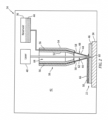
- FIG. 1 schematically illustrates an exemplary system 20 for adaptively manufacturing (e.g., overhauling or forming) the component 22.
- This manufacturing system 20 includes an automated additive manufacturing (AM) device 24 (e.g., a three-dimensional (3D) printer), a furnace 26, an automated machining device 28 (e.g., a computer numerical control (CNC) machining device) and a scanning device 30.
- the manufacturing system 20 of FIG. 1 also includes a controller 32 in signal communication (e.g., hardwired and/or wirelessly coupled) with one or more or all of the other manufacturing system components 24, 26, 28 and 30.
- AM automated additive manufacturing
- CNC computer numerical control
- the additive manufacturing device 24 may be configured as a laser material deposition device. More particularly, the additive manufacturing device 24 may be configured as a direct laser braze cladding (DLBC) device.
- the additive manufacturing device 24 of FIG. 2 includes a component support 34, a material reservoir 36, a nozzle 38 and a laser 40.
- the component support 34 is located within an internal build chamber 42 of the additive manufacturing device 24. This component support 34 is configured to support the component 22 within the build chamber 42.
- the component 22, for example, may be placed on top of the component support 34.
- the component 22 may also or alternatively be mounted to the component support 34 via a fixture, which fixture may arrange the component 22 in a fixed position and/or in a known spatial orientation within the build chamber 42.
- the material reservoir 36 is configured to store a quantity of braze powder 44 formed from braze material. This material reservoir 36 is also configured to supply the braze powder 44 to the nozzle 38 during additive manufacturing device operation. Examples of the material reservoir 36 include, but are not limited to, a tank, a hopper and a bin.
- the nozzle 38 is configured to deliver the braze powder 44 received from the material reservoir 36 to a substrate 46 of the component 22 during additive manufacturing device operation. More particularly, the nozzle 38 is configured to direct a (e.g., annular, conical) stream 48 of the braze powder 44 towards (e.g., to) a surface 50 of the substrate 46.
- the nozzle 38 of FIG. 2 for example, includes a tubular inner sidewall 52 and a tubular outer sidewall 54.
- the outer sidewall 54 extends axially along and circumscribes the inner sidewall 52 so as to form a passage 56 (e.g., an annulus) between the inner sidewall 52 and the outer sidewall 54.
- This passage 56 is fluidly coupled with an outlet from the material reservoir 36, and the passage 56 extends axially within the nozzle 38 to a (e.g., annular) nozzle orifice 58.
- a distal end portion of the nozzle 38 and its inner sidewall 52 and its outer sidewall 54 may radially taper inwards as the nozzle 38 extends axially towards (e.g., to) the nozzle orifice 58.
- the nozzle 38 may focus the braze powder 44 to, around or about a target point 60 on, slightly above or slightly below the substrate surface 50.
- the nozzle 38 may be configured to deliver the braze powder 44 through an internal bore rather than an annulus.
- the laser 40 is configured to generate a laser beam 62 for sintering the braze powder 44 delivered by the nozzle 38 together and to the substrate 46.
- the term "sintering” may describe a process for coalescing powder particles together into a (e.g., porous) mass by heating without (e.g., partial or complete) liquification of the powder. This is in contrast to, for example, a powder laser welding process where powder is melted to a liquid state (e.g., in a melt pool) by a laser beam and then solidified as a solid mass.
- the laser beam 62 of FIG. 2 is configured to direct the laser beam 62 to or about the target point 60, where the laser beam 62 may be incident with and is operable to heat up the braze powder 44 for sintering.
- the laser beam 62 of FIG. 2 is directed through an (e.g., central) internal bore 64 of the nozzle 38, which internal nozzle bore 64 may be formed by the inner sidewall 52.
- the laser 40 may be configured to direct the laser beam 62 outside of the nozzle 38 or along another path through the nozzle 38.
- the furnace 26 is configured to receive the substrate 46 with the sintered braze material 66 within an internal treatment chamber 68 of the furnace 26.
- the furnace 26 is further configured to subject the substrate 46 and the sintered braze material 66 to a heat cycle, for example under vacuum and/or in a partial pressure inert gas (e.g., argon (Ar) gas) environment.
- a partial pressure inert gas e.g., argon (Ar) gas
- the sintered braze material 66 may melt and diffusion bond to the substrate 46.
- An example of the furnace 26 is a vacuum furnace.
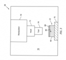
- the machining device 28 includes a manipulator 70, a head 72 and at least one machining tool 74 mated with the head 72.
- the machining device 28 of FIG. 3 also includes a component support 76, which may be the same as or similar to the component support 34 of FIG. 2 .
- the manipulator 70 is configured to move the head 72 and the machining tool 74 within an internal machining chamber 78 of the machining device 28 relative to the component 22.
- the manipulator 70 for example, may be a multi-axis (e.g., 3-axis, 5-axis, 7-axis, etc.) manipulator such as, but not limited to, a robotic arm and/or a gantry system.
- the head 72 is configured to hold the machining tool 74.
- the head 72 is also configured to facilitate actuation of the machining tool 74; e.g., rotate the machining tool 74 about an axis.
- the machining tool 74 is configured to machine the component 22; e.g., remove material from the component 22.
- Examples of the machining tool 74 include, but are not limited to, a drill bit, a milling bit, a milling cutter, a grinding bit, a sanding bit and a polishing bit.
- the machining tool 74 may be a lathe bit where, for example, the component 22 is moved (e.g., rotated) relative to the machining tool 74.
- the present disclosure is not limited to such an exemplary machining device with one or more machining tools; e.g., rotatable bits.
- the machining device 28 may also or alternatively include a laser to laser machine the component 22 within the machining chamber 78 and/or an electrical discharge machining (EDM) device to machine the component 22 within the machining chamber 78.
- EDM electrical discharge machining
- the scanning device 30 of FIG. 1 is configured to map a surface geometry of, one or more dimensions of and/or one or more spatial coordinates for a portion (or multiple portions) of or an entirety of an exterior of the component 22.
- the term "map" may describe a process of determining (e.g., measuring) and collecting certain information.
- the scanning device 30 may also be configured to map a geometry of, one or more dimensions of and/or one or more spatial coordinates for a feature (or multiple features) projecting into the component 22; e.g., an opening to a void 80 such as, but not limited to, a crack, a fracture, a slice, a gouge, a dimple, etc.
- This scanning device 30 is configured as a structured light scanning device; e.g., a structured white light scanning device or a structured blue light scanning device.
- This scanning device 30 is configured to project a pattern of light (e.g., structured white light, structured blue light) onto the component 22 using one or more light projectors, which pattern of light may be formed by white light (e.g., with a wavelength between 400-700nm) or blue light (e.g., with a wavelength between 450-495nm).
- the scanning device 30 is configured to pick up (e.g., image, capture, detect, etc.) distortions in the pattern of light against the exterior of the component 22 using one or more imaging devices; e.g., cameras.
- the scanning device 30 is further configured to map the component 22 based on the distortions in the pattern of light.
- the controller 32 may be implemented with a combination of hardware and software.
- the hardware may include at least one processing device 82 and a memory 84, which processing device 82 may include one or more single-core and/or multi-core processors.
- the hardware may also or alternatively include analog and/or digital circuitry other than that described above.
- the memory 84 is configured to store software (e.g., program instructions) for execution by the processing device 82, which software execution may control and/or facilitate performance of one or more operations such as those described below.
- the memory 84 may be a non-transitory computer readable medium.
- the memory 84 may be configured as or include a volatile memory and/or a nonvolatile memory.
- Examples of a volatile memory may include a random access memory (RAM) such as a dynamic random access memory (DRAM), a static random access memory (SRAM), a synchronous dynamic random access memory (SDRAM), a video random access memory (VRAM), etc.
- RAM random access memory
- DRAM dynamic random access memory
- SRAM static random access memory
- SDRAM synchronous dynamic random access memory
- VRAM video random access memory
- Examples of a nonvolatile memory may include a read only memory (ROM), an electrically erasable programmable read-only memory (EEPROM), a computer hard drive, etc.
- ROM read only memory
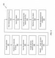
- FIG. 4 is a flow diagram of an exemplary adaptive method 400 for manufacturing (e.g., overhauling or forming) the component 22.
- the manufacturing method 400 is described with respect to the manufacturing system 20 and overhauling the component 22.
- the manufacturing method 400 is not limited to any particular manufacturing system types or configurations.
- some or all of the method steps may alternatively be performed to form a new component.
- the substrate 46 is provided.
- this substrate 46 is described as part of a damaged component; e.g., a worn and/or cracked component previously installed within an engine.
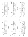
- the component 22 of FIG. 5 includes at least one void 80.
- This void 80 projects partially into the component 22 and its substrate 46 from the exterior of the component 22.
- the component 22 of FIG. 5 also includes a wear region 86 where a portion of the component 22 and its substrate 46 has been worn away due to, for example, erosion, rubbing and/or otherwise.
- the component 22 may include multiple voids 80, multiple wear regions 86, the void(s) 80 without any wear region, the wear region(s) 86 without any void, and/or one or more other substrate defects.
- the substrate 46 is prepared for the braze powder 44.
- a coating 88 (see FIG. 5 ) over at least a portion or an entirety of the substrate 46, for example, may be removed to expose the underlying substrate 46 and its substrate surface 50.
- the coating 88 may be removed using various techniques such as, but not limited to, chemical stripping, abrasive blasting, waterjet blasting and/or machining.
- the void 80 may be machined (e.g., enlarged, smoothed, etc.), cleaned out and/or otherwise processed.
- This preparation step 404 may be performed by the machining device 28 and/or other devices part of or discrete from the manufacturing system 20.
- the substrate 46 is scanned using structured light; e.g., structured white or blue light.
- the scanning device 30 of FIG. 1 scans the substrate 46 of FIG. 6 to map one or more exterior characteristics of the substrate 46 and/or one or more interior characteristic of the substrate 46.
- the exterior substrate characteristics include, but are not limited to, a surface geometry of, one or more dimensions of and/or one or more spatial coordinates for a portion (or multiple portions) of or an entirety of an exterior of the substrate 46.
- the interior substrate characteristics include, but are not limited to, a geometry of, one or more dimensions of and/or one or more spatial coordinates for a feature (or multiple features) projecting into the substrate 46; e.g., the opening to the void 80.
- the scanning device 30 then provides substrate scan data to the controller 32 indicative of the one or more mapped substrate characteristics.
- the substrate scan data may be in the form of a computer aided design (CAD) model file; e.g., a stereolithography (STL) model file.
- CAD computer aided design
- STL stereolithography
- the substrate scan data is processed to provide additive manufacturing (AM) data.
- the controller 32 of FIG. 1 may compare (e.g., align) the one or more mapped substrate 46 characteristics from the substrate scan data with respective characteristics from substrate reference data.
- This substrate reference data may be data input from (or derived from) a (e.g., original equipment manufacturer (OEM)) design specification for the component 22.
- OEM original equipment manufacturer
- the controller 32 may compare the one or more mapped characteristics for the substrate 46 being worked on (e.g., overhauled) to one or more corresponding characteristics of a (e.g., theoretical) design space component; e.g., a component formed according to the design specification.
- the controller 32 may generate a solid model of the scanned substrate 46 to compare to a solid model of the design space component.
- the controller 32 may thereby evaluate the current state / condition of the substrate 46, and determine what additive operations may be performed (e.g., determine amount(s) of the braze powder to deposit, determine where to deposit the braze powder, determine path(s) to follow for the depositing of the braze powder, etc.) to place the substrate 46 of FIG. 6 into like new (or new) condition; e.g., to have the same (or similar) characteristics as the design space component.
- the controller 32 may identify material deficits between the solid model of the scanned substrate 46 and the solid model of the design space component, and determine how to fill those material deficits with the braze powder.
- the additive manufacturing data may include one or more commands for the additive manufacturing device 24 to place the substrate 46 of FIG. 6 into the like new (or new) condition.
- the braze powder is deposited with the substrate 46 using the additive manufacturing device 24.
- the additive manufacturing device 24 may deposit the braze powder 44 onto the substrate surface 50 at or about the target point 60.
- the laser 40 may concurrently sinter this braze powder 44 at the target point 60 together and/or to the underlying substrate 46.
- the additive manufacturing device 24 may be positioned and operated to provide the sintered braze material 66 within the void 80; e.g., to partially or completely fill the void 80.
- the additive manufacturing device 24 may also or alternatively be positioned and operated to provide a cladding (e.g., a layer or multiple layers) of the sintered braze material 66 over the wear region 86; e.g., to build back worn away substrate material.
- the additive manufacturing device 24 may selectively deposit the braze powder over the substrate 46 such that (e.g., only) areas which need repair (and optionally areas adjacent and/or surrounding those areas) are filled with the sintered braze material 66 and/or coated with the sintered braze material 66.
- the braze powder may be deposited over an entirety of the substrate 46 where excess material may later be removed.
- the braze powder may be deposited (e.g., built up) as one or more layers during the step 410.
- the braze powder 44 may include a mixture of metal alloy powder (e.g., substrate powder) and braze material powder.
- the metal alloy powder may be selected to have a relatively high melting point and common (the same) or similar material properties as the substrate 46.
- the metal alloy powder for example, may be made from a common (or a similar) material as the underlying substrate 46; e.g., an aluminum (Al) superalloy, a nickel (Ni) superalloy, a titanium (Ti) superalloy, etc.
- the braze material powder on the other hand, may be selected to have a relatively low melting point, which is lower than the melting point of the metal alloy powder.
- the braze material powder may include a common or similar base element as the substrate 46 and/or the metal alloy powder (e.g., aluminum (Al), nickel (Ni) or titanium (Ti)) without the super alloying elements.
- the brazing powder may also include boron (B), silicon (Si) and/or other melting point suppressants which may help facilitate melting and diffusion of the metal alloy powder with the substrate 46.
- B boron
- Si silicon
- the present disclosure is not limited to the foregoing exemplary braze materials.
- the braze powder 44 may include various proportions of the metal alloy powder and the braze material powder.
- the braze powder 44 may include more of the braze material powder than the metal alloy powder to fill voids within the substrate 46; e.g., to increase wettability, flowability and/or capillary penetration of the braze powder.
- the braze powder 44 may include more of the metal alloy powder than the braze material powder to form a cladding over the substrate 46.
- the braze powder 44 may include the same amount of the metal alloy powder as the braze material powder.
- the substrate 46 and the sintered braze material 66 are heated.
- the substrate 46 with the sintered braze material 66 may be arranged within the treatment chamber 68 of the furnace 26 of FIG. 1 .
- the furnace 26 may subject the substrate 46 with the sintered braze material 66 to a heat cycle. More particularly, the substrate 46 with the sintered braze material 66 may be heated to an elevated temperature within a partial pressure inert gas environment. The elevated temperature is selected such that the sintered braze material 66 melts and flows into defects of the substrate 46 by capillary action. Once the sintered braze material has melted, a relatively lower temperature may be selected and held in the same heat cycle for a duration.
- This sustained temperature may facilitate diffusion of the melting point suppressant material.
- This diffusion of the melting point suppressant material may facilitate athermal solidification, resulting in a braze diffusion bond of the sintered material to the substrate 46.
- the athermal solidification may describe solidification of the melted sintered braze material under, for example, a constant temperature.
- the diffusion duration may be between four (4) hours and twelve (12) hours, but may be much shorter or longer depending on materials being diffusion brazed and/or desired material properties and diffusion bonds to the substrate 46.
- This elevated temperature is less than a melting point temperature of the substrate material.
- the elevated temperature for the braze melt for example, may be between 1,500°F (816°C) and 2,500°F (1371°C).
- the elevated temperature for the braze diffusion may be between 1,000°F (538°C) and 2,400°F (1316°C).
- the inert gas environment may have a vacuum pressure range between, for example, 0.5 microns and 0.1 microns.
- the present disclosure is not limited to the foregoing exemplary heat cycle parameters, and the foregoing heat cycle parameters may vary depending upon the specific material composition of the substrate 46 and the braze material, dimensions (e.g., thickness) of the sintered brazed powder, etc.
- braze filler material 88 (e.g., diffusion bonded braze material) of FIG. 8 may heal the void 80.
- the braze filler material 88 may partially or completely fill the void 80.
- the braze filler material 88 may also or alternatively provide a cladding over the substrate 46 to restore a dimensional parameter of and/or reinforce the wear region 86.
- the braze filler material 88 may buildup the wear region 86 back to or above a dimensional parameter specified therefor by a design specification or an overhaul specification for the component 22.
- a first object 90 (e.g., the substrate 46 with the braze filler material 88) is scanned using structured light.
- the scanning device 30 of FIG. 1 scans the first object 90 of FIG. 8 to map one or more exterior characteristics of the first object 90 and/or one or more interior characteristic of the first object 90.
- the exterior first object characteristics include, but are not limited to, a surface geometry of, one or more dimensions of and/or one or more spatial coordinates for a portion (or multiple portions) of or an entirety of an exterior of the first object 90.
- the interior first object characteristics include, but are not limited to, a geometry of, one or more dimensions of and/or one or more spatial coordinates for a feature (or multiple features) projecting into the first object 90; e.g., a void.
- the scanning device 30 then provides first object scan data to the controller 32 indicative of the one or more mapped first object characteristics.
- the first object scan data may be in the form of a computer aided design (CAD) model file; e.g., a stereolithography (STL) model file.
- CAD computer aided design
- STL stereolithography
- the first object scan data is processed to provide machining data.
- the controller 32 of FIG. 1 may compare (e.g., align) the one or more mapped first object characteristics from the first object scan data with one or more respective mapped substrate characteristics from the substrate scan data; e.g., the pre-additive manufacturing scan data.
- the controller 32 may also or alternatively compare (e.g., align) the one or more mapped first object characteristics from the first object scan data with respective characteristics from other first object reference data.
- This other first object reference data may be data input from (or derived from) the design specification for the component 22.
- the controller 32 may thereby evaluate the current state / condition of the first object 90, and determine what subtractive operations may be performed (e.g., amounts of material to be removed, where to remove the material, path(s) for the machining tool 74 to follow, etc.) to place the first object 90 of FIG. 8 into like new (or new) condition; e.g., to have the same (or similar) characteristics as the design space component.
- the additive manufacturing data may include one or more commands for the machining device 28 to place the first object 90 of FIG. 8 into the like new (or new) condition.
- a second object 92 is formed.
- the machining device 28 of FIG. 3 selectively removes material from the first object 90 to form the second object 92.
- This first object material is removed based on / according to the machining data; e.g., command(s) provided by the controller 32.
- the first object material may thereby be selectively removed to at least partially restore or otherwise place the component 22 into the like new (or new) condition.
- the material removed from the first object 90 may include some of the braze filler material 88 and/or some of the substrate material. This material may be removed by the machining device 28 through drilling, cutting, grinding, milling, polishing, sanding and/or otherwise.
- the second object 92 may be processed to provide an overhauled / restored component.
- One or more coatings 94 may be applied to the second object 92 (see FIG. 10 ). Examples of these coatings 94 include, but are not limited to, bond coating(s), environmental coating(s), thermal barrier coating(s), etc.
- the braze powder 44 and the laser beam 62 may be concurrently directed to the common target point 60 for the braze powder deposition. In other embodiments, however, the laser beam 62 may alternatively be directed to a different target point than the braze powder 44.
- the laser beam target point for example, may alternatively be spaced from and follow the braze powder target point.
- the braze powder 44 may be sintered using the laser beam 62.
- the present disclosure is not limited to use of such an exemplary energy beam.
- the braze powder 44 may alternatively be sintered using an electron beam provided by an electron beam source.
- multiple energy beams e.g., laser beams and/or electron beams
- multiple nozzles 38 may be used to deliver the braze powder 44.
- a component manufactured using a typical additive laser deposition welding process may be subject to: internal stresses thermally induced by relatively high welding temperatures (e.g., temperatures high enough to melt the substrate material); thermally induced distortion and/or warping; and/or reduction in material density caused by, for example, dendritic voids.
- sintering the braze powder 44 with the substrate 46 and then diffusion bonding the braze powder with the substrate 46 as described above subjects the substrate 46 to relatively low processing temperatures, compared to welding temperatures.
- the manufacturing methods of the present disclosure may thereby reduce or eliminate: thermally induced stresses; thermally induced distortion and/or warping; and/or reduction in material density associated with additive laser deposition welding techniques.
- the above laser braze cladding technique is also paired with the adaptive processing to reduce material consumption and/or require less post processing (e.g., machining, finishing, etc.) compared to traditional manual brazing techniques.
Landscapes
- Engineering & Computer Science (AREA)
- Chemical & Material Sciences (AREA)
- Materials Engineering (AREA)
- Mechanical Engineering (AREA)
- Manufacturing & Machinery (AREA)
- Physics & Mathematics (AREA)
- Optics & Photonics (AREA)
- Plasma & Fusion (AREA)
- Composite Materials (AREA)
- General Engineering & Computer Science (AREA)
- Thermal Sciences (AREA)
- Powder Metallurgy (AREA)
Applications Claiming Priority (1)
| Application Number | Priority Date | Filing Date | Title |
|---|---|---|---|
| US17/942,067 US12358232B2 (en) | 2022-09-09 | 2022-09-09 | Adaptive manufacturing using structured light data |
Publications (1)
| Publication Number | Publication Date |
|---|---|
| EP4335573A1 true EP4335573A1 (fr) | 2024-03-13 |
Family
ID=88016202
Family Applications (1)
| Application Number | Title | Priority Date | Filing Date |
|---|---|---|---|
| EP23196313.3A Pending EP4335573A1 (fr) | 2022-09-09 | 2023-09-08 | Fabrication adaptative utilisant des données de lumière structurée |
Country Status (3)
| Country | Link |
|---|---|
| US (1) | US12358232B2 (fr) |
| EP (1) | EP4335573A1 (fr) |
| CA (1) | CA3211296A1 (fr) |
Families Citing this family (1)
| Publication number | Priority date | Publication date | Assignee | Title |
|---|---|---|---|---|
| US12551974B2 (en) * | 2022-09-09 | 2026-02-17 | Pratt & Whitney Canada Corp. | Adaptive component overhaul using structured light scan data |
Citations (8)
| Publication number | Priority date | Publication date | Assignee | Title |
|---|---|---|---|---|
| EP1561536A1 (fr) * | 2004-02-03 | 2005-08-10 | Siemens Aktiengesellschaft | Procédé de réparation par brasage d'une pièce ayant un matériau de base avec une microstructure orientée |
| EP1685923A1 (fr) * | 2005-01-27 | 2006-08-02 | United Technologies Corporation | Réparation et re-élaboration de composants en superalliages |
| WO2015161980A1 (fr) * | 2014-04-23 | 2015-10-29 | Siemens Aktiengesellschaft | Procédé de fabrication d'une pièce |
| CN103753098B (zh) * | 2013-12-31 | 2016-08-31 | 成都青石激光科技有限公司 | 涡轮发动机叶片自动化修复设备及其修复方法 |
| EP3202529A1 (fr) * | 2016-02-05 | 2017-08-09 | MTU Aero Engines GmbH | Procédé de réparation d'aubes statoriques de turbine |
| US20180281125A1 (en) * | 2015-10-07 | 2018-10-04 | Siemens Aktiengesellschaft | Repairing a part having cracks, and part |
| DE102019203796A1 (de) * | 2019-03-20 | 2020-09-24 | MTU Aero Engines AG | Verfahren zum Bestimmen von zu reparierenden Bereichen eines additiv hergestellten Bauelements |
| FR3103401A1 (fr) * | 2019-11-22 | 2021-05-28 | Safran Aircraft Engines | Procédé d’addition de matière |
Family Cites Families (21)
| Publication number | Priority date | Publication date | Assignee | Title |
|---|---|---|---|---|
| US8140179B2 (en) | 2007-01-19 | 2012-03-20 | S.E. Huffman Corp. | Method and apparatus for repairing turbine components |
| JP2009025119A (ja) | 2007-07-19 | 2009-02-05 | General Electric Co <Ge> | 輪郭測定装置及び動作方法 |
| US20090026182A1 (en) * | 2007-07-27 | 2009-01-29 | Honeywell International, Inc. | In-situ brazing methods for repairing gas turbine engine components |
| CH704448A1 (de) | 2011-02-03 | 2012-08-15 | Alstom Technology Ltd | Verfahren zum Reparieren bzw. Rekonditionieren eines stark beschädigten Bauteils, insbesondere aus dem Heissgasbereich einer Gasturbine. |
| ITCO20120040A1 (it) | 2012-09-07 | 2014-03-08 | Nuovo Pignone Srl | Metodo per la riparazione di un componente di turbomacchina |
| EP2712697A1 (fr) * | 2012-10-01 | 2014-04-02 | Siemens Aktiengesellschaft | Dispositif d'allimentation de poudre pour un dispositif de rechargement par soudure de poudre laser |
| DE102012221782A1 (de) | 2012-11-28 | 2014-05-28 | Lufthansa Technik Ag | Verfahren und Vorrichtung zur Reparatur eines Flugzeug- und/oder Gasturbinen-Bauteils |
| DE112013006029B4 (de) | 2012-12-17 | 2025-05-08 | Arcam Ab | Verfahren und Vorrichtung zum Ausbilden eines dreidimensionalen Gegenstands |
| US9764517B2 (en) | 2013-01-07 | 2017-09-19 | Bae Systems Plc | Object production using an additive manufacturing process and quality assessment of the object |
| US9174312B2 (en) | 2013-03-12 | 2015-11-03 | Honeywell International Inc. | Methods for the repair of gas turbine engine components using additive manufacturing techniques |
| US20180243866A1 (en) * | 2017-02-28 | 2018-08-30 | General Electric Company | Turbine component repair with additive manufacturing |
| US11097350B2 (en) | 2017-07-24 | 2021-08-24 | Raytheon Technologies Corporation | Pre-fusion laser sintering for metal powder stabilization during additive manufacturing |
| EP3450055A1 (fr) | 2017-08-30 | 2019-03-06 | Siemens Aktiengesellschaft | Procédé de fabrication additive d'une structure de pointe sur une partie préexistante |
| WO2019177607A1 (fr) | 2018-03-15 | 2019-09-19 | Siemens Energy, Inc. | Fabrication additive à fil de brasage laser d'un élément d'aube de turbine en super-solution avec refroidissement au-dessous de zéro |
| US11999012B2 (en) | 2018-03-27 | 2024-06-04 | Siemens Energy, Inc. | Method and system for additive manufacturing or repair with in-situ manufacturing and feeding of a sintered wire |
| US10814439B2 (en) | 2018-05-31 | 2020-10-27 | General Electric Company | Turbomachine repair using additive manufacturing |
| US11285538B2 (en) | 2019-01-30 | 2022-03-29 | General Electric Company | Tooling assembly and method for aligning components for a powder bed additive manufacturing repair process |
| FR3096297B1 (fr) | 2019-05-23 | 2024-01-19 | Inst De Rech Tech Jules Verne | Procédé de réparation d’une pièce en cours de fabrication additive |
| FR3096296B1 (fr) | 2019-05-23 | 2023-11-24 | Inst De Rech Tech Jules Verne | Procédé de fabrication additive |
| CN113441725B (zh) | 2020-03-27 | 2023-09-22 | 斗山重工业建设有限公司 | 利用增材制造的涡轮机叶片的修复方法 |
| EP3933527A1 (fr) * | 2020-07-03 | 2022-01-05 | Siemens Aktiengesellschaft | Procédé et agencement de réparation d'une pièce |
-
2022
- 2022-09-09 US US17/942,067 patent/US12358232B2/en active Active
-
2023
- 2023-09-06 CA CA3211296A patent/CA3211296A1/fr active Pending
- 2023-09-08 EP EP23196313.3A patent/EP4335573A1/fr active Pending
Patent Citations (8)
| Publication number | Priority date | Publication date | Assignee | Title |
|---|---|---|---|---|
| EP1561536A1 (fr) * | 2004-02-03 | 2005-08-10 | Siemens Aktiengesellschaft | Procédé de réparation par brasage d'une pièce ayant un matériau de base avec une microstructure orientée |
| EP1685923A1 (fr) * | 2005-01-27 | 2006-08-02 | United Technologies Corporation | Réparation et re-élaboration de composants en superalliages |
| CN103753098B (zh) * | 2013-12-31 | 2016-08-31 | 成都青石激光科技有限公司 | 涡轮发动机叶片自动化修复设备及其修复方法 |
| WO2015161980A1 (fr) * | 2014-04-23 | 2015-10-29 | Siemens Aktiengesellschaft | Procédé de fabrication d'une pièce |
| US20180281125A1 (en) * | 2015-10-07 | 2018-10-04 | Siemens Aktiengesellschaft | Repairing a part having cracks, and part |
| EP3202529A1 (fr) * | 2016-02-05 | 2017-08-09 | MTU Aero Engines GmbH | Procédé de réparation d'aubes statoriques de turbine |
| DE102019203796A1 (de) * | 2019-03-20 | 2020-09-24 | MTU Aero Engines AG | Verfahren zum Bestimmen von zu reparierenden Bereichen eines additiv hergestellten Bauelements |
| FR3103401A1 (fr) * | 2019-11-22 | 2021-05-28 | Safran Aircraft Engines | Procédé d’addition de matière |
Also Published As
| Publication number | Publication date |
|---|---|
| US20240083118A1 (en) | 2024-03-14 |
| CA3211296A1 (fr) | 2024-03-09 |
| US12358232B2 (en) | 2025-07-15 |
Similar Documents
| Publication | Publication Date | Title |
|---|---|---|
| EP4335574A1 (fr) | Dépôt adaptatif de matériau de brasage à l'aide de données de balayage de lumière structurée | |
| US12251757B2 (en) | Adaptively depositing braze material(s) using CT scan data | |
| CA2284759C (fr) | Processus de fabrication ou de reparation de composants de moteur a turbine ou de compresseur | |
| US20250345856A1 (en) | Adaptive manufacturing using ct scan data | |
| EP4335571A1 (fr) | Dépôt additif de multiples matériaux de brasure | |
| US12115598B2 (en) | Adaptive overhaul using plural scanning methods | |
| EP4335573A1 (fr) | Fabrication adaptative utilisant des données de lumière structurée | |
| EP4335567A1 (fr) | Révision adaptative de composant utilisant des données de balayage de lumière structurée | |
| EP4335566A1 (fr) | Fabrication additive à l'aide de données de balayage ct | |
| EP4335569A1 (fr) | Dépôt additif de matériau de brasage | |
| EP4424443A1 (fr) | Fabrication d'un composant à l'aide de matériaux de brasage à point de fusion élevé et bas | |
| US12617018B2 (en) | Adaptive overhaul with two braze material and structured light scans | |
| EP4414102A1 (fr) | Révision adaptative utilisant un ensemble de données unique à lumière structurée | |
| US20240293869A1 (en) | Adaptive overhaul with two braze material and structured light scans | |
| US20240293868A1 (en) | Adaptive overhaul with two braze material and ct scans | |
| EP4414100A1 (fr) | Fabrication adaptative utilisant un trajet d'outil de fabrication adaptatif | |
| US20240269748A1 (en) | Adaptive overhaul using ct scan single data set |
Legal Events
| Date | Code | Title | Description |
|---|---|---|---|
| PUAI | Public reference made under article 153(3) epc to a published international application that has entered the european phase |
Free format text: ORIGINAL CODE: 0009012 |
|
| STAA | Information on the status of an ep patent application or granted ep patent |
Free format text: STATUS: THE APPLICATION HAS BEEN PUBLISHED |
|
| AK | Designated contracting states |
Kind code of ref document: A1 Designated state(s): AL AT BE BG CH CY CZ DE DK EE ES FI FR GB GR HR HU IE IS IT LI LT LU LV MC ME MK MT NL NO PL PT RO RS SE SI SK SM TR |
|
| STAA | Information on the status of an ep patent application or granted ep patent |
Free format text: STATUS: REQUEST FOR EXAMINATION WAS MADE |
|
| 17P | Request for examination filed |
Effective date: 20240913 |
|
| RBV | Designated contracting states (corrected) |
Designated state(s): AL AT BE BG CH CY CZ DE DK EE ES FI FR GB GR HR HU IE IS IT LI LT LU LV MC ME MK MT NL NO PL PT RO RS SE SI SK SM TR |