EP4335583A1 - Dispositif de changement d'outil pour une machine-outil et système de fabrication - Google Patents
Dispositif de changement d'outil pour une machine-outil et système de fabrication Download PDFInfo
- Publication number
- EP4335583A1 EP4335583A1 EP23196124.4A EP23196124A EP4335583A1 EP 4335583 A1 EP4335583 A1 EP 4335583A1 EP 23196124 A EP23196124 A EP 23196124A EP 4335583 A1 EP4335583 A1 EP 4335583A1
- Authority
- EP
- European Patent Office
- Prior art keywords
- tool
- magazine
- gripper
- changing device
- tool magazine
- Prior art date
- Legal status (The legal status is an assumption and is not a legal conclusion. Google has not performed a legal analysis and makes no representation as to the accuracy of the status listed.)
- Pending
Links
Images




Classifications
-
- B—PERFORMING OPERATIONS; TRANSPORTING
- B23—MACHINE TOOLS; METAL-WORKING NOT OTHERWISE PROVIDED FOR
- B23Q—DETAILS, COMPONENTS, OR ACCESSORIES FOR MACHINE TOOLS, e.g. ARRANGEMENTS FOR COPYING OR CONTROLLING; MACHINE TOOLS IN GENERAL CHARACTERISED BY THE CONSTRUCTION OF PARTICULAR DETAILS OR COMPONENTS; COMBINATIONS OR ASSOCIATIONS OF METAL-WORKING MACHINES, NOT DIRECTED TO A PARTICULAR RESULT
- B23Q7/00—Arrangements for handling work specially combined with or arranged in, or specially adapted for use in connection with, machine tools, e.g. for conveying, loading, positioning, discharging, sorting
- B23Q7/04—Arrangements for handling work specially combined with or arranged in, or specially adapted for use in connection with, machine tools, e.g. for conveying, loading, positioning, discharging, sorting by means of grippers
- B23Q7/046—Handling workpieces or tools
-
- B—PERFORMING OPERATIONS; TRANSPORTING
- B23—MACHINE TOOLS; METAL-WORKING NOT OTHERWISE PROVIDED FOR
- B23Q—DETAILS, COMPONENTS, OR ACCESSORIES FOR MACHINE TOOLS, e.g. ARRANGEMENTS FOR COPYING OR CONTROLLING; MACHINE TOOLS IN GENERAL CHARACTERISED BY THE CONSTRUCTION OF PARTICULAR DETAILS OR COMPONENTS; COMBINATIONS OR ASSOCIATIONS OF METAL-WORKING MACHINES, NOT DIRECTED TO A PARTICULAR RESULT
- B23Q3/00—Devices holding, supporting, or positioning work or tools, of a kind normally removable from the machine
- B23Q3/155—Arrangements for automatic insertion or removal of tools, e.g. combined with manual handling
- B23Q3/157—Arrangements for automatic insertion or removal of tools, e.g. combined with manual handling of rotary tools
- B23Q3/15713—Arrangements for automatic insertion or removal of tools, e.g. combined with manual handling of rotary tools a transfer device taking a single tool from a storage device and inserting it in a spindle
- B23Q3/1572—Arrangements for automatic insertion or removal of tools, e.g. combined with manual handling of rotary tools a transfer device taking a single tool from a storage device and inserting it in a spindle the storage device comprising rotating or circulating storing means
- B23Q3/15722—Rotary discs or drums
-
- B—PERFORMING OPERATIONS; TRANSPORTING
- B23—MACHINE TOOLS; METAL-WORKING NOT OTHERWISE PROVIDED FOR
- B23Q—DETAILS, COMPONENTS, OR ACCESSORIES FOR MACHINE TOOLS, e.g. ARRANGEMENTS FOR COPYING OR CONTROLLING; MACHINE TOOLS IN GENERAL CHARACTERISED BY THE CONSTRUCTION OF PARTICULAR DETAILS OR COMPONENTS; COMBINATIONS OR ASSOCIATIONS OF METAL-WORKING MACHINES, NOT DIRECTED TO A PARTICULAR RESULT
- B23Q3/00—Devices holding, supporting, or positioning work or tools, of a kind normally removable from the machine
- B23Q3/155—Arrangements for automatic insertion or removal of tools, e.g. combined with manual handling
- B23Q3/1552—Arrangements for automatic insertion or removal of tools, e.g. combined with manual handling parts of devices for automatically inserting or removing tools
- B23Q3/15526—Storage devices; Drive mechanisms therefor
-
- B—PERFORMING OPERATIONS; TRANSPORTING
- B23—MACHINE TOOLS; METAL-WORKING NOT OTHERWISE PROVIDED FOR
- B23Q—DETAILS, COMPONENTS, OR ACCESSORIES FOR MACHINE TOOLS, e.g. ARRANGEMENTS FOR COPYING OR CONTROLLING; MACHINE TOOLS IN GENERAL CHARACTERISED BY THE CONSTRUCTION OF PARTICULAR DETAILS OR COMPONENTS; COMBINATIONS OR ASSOCIATIONS OF METAL-WORKING MACHINES, NOT DIRECTED TO A PARTICULAR RESULT
- B23Q3/00—Devices holding, supporting, or positioning work or tools, of a kind normally removable from the machine
- B23Q3/155—Arrangements for automatic insertion or removal of tools, e.g. combined with manual handling
- B23Q3/1552—Arrangements for automatic insertion or removal of tools, e.g. combined with manual handling parts of devices for automatically inserting or removing tools
- B23Q3/1554—Transfer mechanisms, e.g. tool gripping arms; Drive mechanisms therefore
-
- B—PERFORMING OPERATIONS; TRANSPORTING
- B23—MACHINE TOOLS; METAL-WORKING NOT OTHERWISE PROVIDED FOR
- B23Q—DETAILS, COMPONENTS, OR ACCESSORIES FOR MACHINE TOOLS, e.g. ARRANGEMENTS FOR COPYING OR CONTROLLING; MACHINE TOOLS IN GENERAL CHARACTERISED BY THE CONSTRUCTION OF PARTICULAR DETAILS OR COMPONENTS; COMBINATIONS OR ASSOCIATIONS OF METAL-WORKING MACHINES, NOT DIRECTED TO A PARTICULAR RESULT
- B23Q3/00—Devices holding, supporting, or positioning work or tools, of a kind normally removable from the machine
- B23Q3/155—Arrangements for automatic insertion or removal of tools, e.g. combined with manual handling
- B23Q3/1552—Arrangements for automatic insertion or removal of tools, e.g. combined with manual handling parts of devices for automatically inserting or removing tools
- B23Q3/1554—Transfer mechanisms, e.g. tool gripping arms; Drive mechanisms therefore
- B23Q2003/155414—Transfer mechanisms, e.g. tool gripping arms; Drive mechanisms therefore the transfer mechanism comprising two or more grippers
- B23Q2003/155418—Transfer mechanisms, e.g. tool gripping arms; Drive mechanisms therefore the transfer mechanism comprising two or more grippers the grippers moving together
Definitions
- the present disclosure relates to a tool changing device for a machine tool and to a manufacturing system with a machine tool and a tool changing device. According to various aspects, the present disclosure relates to compactly designed machine tools and their integration into manufacturing systems and systems for machining. Compactly designed machine tools are, for example, those with a work area that is smaller than 250 mm x 250 mm x 250 mm.
- the working space of the machine tool is smaller than 200 mm x 200 mm x 200 mm. In exemplary embodiments, the working space of the machine tool is smaller than 150 mm x 150 mm x 150 mm. In exemplary embodiments, the working space of the machine tool is smaller than 100 mm x 100 mm x 100 mm. In exemplary embodiments, the working space of the machine tool is smaller than 75mm x 75mm x 75mm.
- This information particularly concerns the possible feeds (travel paths) along the X, Y and Z axes.
- the workspace can be designed in a cube shape. However, cuboid-shaped installation spaces are also conceivable whose travel paths in X, Y and Z are not uniform. For example, machine tools designed in this way are suitable for precision mechanical processing, for example in the context of the production of watches, jewelry and the like. It goes without saying that other applications are also conceivable, for example in the field of medical technology, precision technology and the like.
- Machine tools and systems for metal-cutting production are known. From the US 2019/0084102 A1 a production system is known which has a plurality of compactly designed machine tools arranged one above the other and next to one another, which are arranged in a common housing, with an additional robot for changing tools and/or workpieces being provided, which is arranged to be horizontally movable on a vertically movable beam.
- the system includes an integrated storage for tools that can be moved with the robot.
- a machine tool with a tool spindle and a workpiece holder as well as with a handling robot is known, which is designed to change workpieces or tools.
- the handling robot is not designed to exchange tools directly with the tool spindle. Instead, a horizontally movable transfer carriage is provided which transfers tools between the handling robot and the tool spindle.
- the tool changing device having a multi-axis robot which has several bending axes and along a horizontal linear axis can be moved between at least one tool magazine and a spindle head of the machine tool in order to change tools.
- the at least one tool magazine is arranged in a stationary manner and is immovable during the tool change.
- the automation technology for example robots with grippers and the like
- the installation space possibly work space of the machine tool in order to enable the transfer of workpieces and, if necessary, tools.
- the present disclosure is based on the object of specifying a tool changing device for a machine tool, the tool changing device being particularly suitable for compact machine tools.
- the tool changing device should, if possible, take particular conditions into account in compactly designed machine tools. With the help of the tool changing device, manufacturing systems should be able to be implemented that enable partially automated or even highly automated production even with only a small installation space. This refers, for example, to changing tools.
- the tool changing device should, if possible, also provide storage capacity, so that at least temporarily self-sufficient or autonomous operation of the machine tool is possible.
- a manufacturing system is to be specified that has a machine tool and a tool changing device that enables an automated tool change and, if necessary, an automated workpiece device change.
- the tool changing device should, if possible, include a plurality of storage locations for tools.
- the manufacturing system should be designed to be compact and user-friendly.
- the handling cell is suitable, at least in exemplary embodiments, for compact machine tools.
- workpieces with only small dimensions can be processed using machine tools with a correspondingly small working space. This has an overall positive effect on the space required (floor space).
- machine tools with only small dimensions and in particular small installation spaces are used, it can be advantageous if the handling unit with the handling robot interacts with the work space as little as possible.
- the first loading interface can be closed by a door, so that the working space is sufficiently separated from the tool changing device when no tool change takes place.
- the handling robot is designed to move at least with the tool gripper through the setup interface into the working space of the machine tool in order to hand over a tool directly to a tool holder or to take it over from it.
- the handling robot can use the tool gripper to move far enough into the work area to change tools there. This includes, for example, a transfer of requested tools to a tool holder as well as a takeover of tools that are no longer required from the tool holder. Since the handling robot is not installed in the work area, the work area is not used by the handling robot if there is no tool change and the handling robot has moved out of the work area with the tool gripper.
- the handling robot is arranged in a cell, which can also be referred to as a setup cell.
- the setup cell has a compact design and is adjacent to the work area of the machine tool. If necessary, the setup interface connects the work area with the setup cell.
- the tool magazine has at least two levels standing one above the other, each of which has a plurality of tool locations.
- each level is formed by a magazine disk.
- the design as a disc magazine simplifies the positioning of tools or tool places for the transfer between the tool magazine and the handling unit.
- Selected tool locations can be positioned using an indexed rotational movement around the vertical longitudinal axis of the tool magazine.
- each level has at least ten tool locations distributed in a circle. In an exemplary embodiment, more than 15 tool positions distributed in a circle are arranged on each level. In an exemplary embodiment, 20 tool positions distributed in a circle are arranged on each level.
- the tool magazine has at least three levels standing one above the other, each of which has a plurality of tool locations, which are distributed in particular along the same diameter around the axis of rotation.
- the levels are each oriented horizontally and offset vertically from one another, at least in exemplary embodiments.
- each of the at least three levels standing one above the other is formed by a magazine disk.
- the magazine disks each have the same diameter. According to this design, the magazine is not designed in a terrace shape.
- the tool magazine is designed to be rigid in itself, with the levels standing one above the other being connected to one another in a rotationally fixed manner via a common center.
- the center is formed by a central profile (such as a central tube) with an axial extension along the longitudinal axis of the tool magazine.
- the two or more levels arranged one above the other are arranged axially offset from one another along the longitudinal axis and are connected to one another, for example via the central profile.
- the levels are radially accessible to the handling unit.
- the central profile nevertheless allows a high level of rigidity; the levels can each extend around it like a ring like a protruding collar.
- the tool magazine has a support surface with which the tool magazine rests on the turntable, the support surface being spaced along a longitudinal extent of the tool magazine at least 30% of the longitudinal extent from a lower end of the tool magazine.
- the lower end of the tool magazine does not rest on the turntable.
- the lower end is the end facing the floor when the tool magazine arranged at the staging area is in an upright orientation.
- the turntable engages axially in the tool magazine at least in sections.
- the tool magazine is supported in the middle. In this way, any tendency to tip over can be minimized.
- the support surface is arranged within a central profile of the tool magazine, with tool locations in the tool magazine being arranged distributed around the central profile.
- the tool magazine with the central profile can be placed over the turntable.
- the tool magazine has a handle for manual handling, in particular for manually changing the tool magazine.
- the handle is designed, for example, as a handle at the upper end of the tool magazine.
- Tools with small dimensions can be used, particularly in machine tools with a compact design.
- HSK tool holders HSK: hollow shaft cone
- an outer diameter of the hollow shaft 40 mm, 32 mm, 25 mm or even 15 mm.
- tool holders with a hollow shaft cone, for example with a nominal diameter of 15 mm .
- a (working) diameter of a tool held in such a tool holder can be, for example, 4-12 mm, but can also be significantly smaller.
- Tools miniaturized in this way are low in weight. Therefore, the tool magazine can also be used on several levels with a plurality of tool positions be moved manually.
- At least one sensor is provided at the staging area for detecting the presence of the tool magazine and/or for detecting the presence of tools in tool locations in the tool magazine.
- this can refer to the mere presence (tool space occupied or not). It is understood that additional information may also be collected if necessary.
- the tool magazine is designed to accommodate tools in a hanging manner, with the tools being covered on the top in particular in the tool magazine.
- This has the advantage that tools in the tool magazine are protected from contamination from above. This can refer to chips, other abrasion, residues of cooling lubricant and the like.
- the levels of the tool magazine which is designed as a disk magazine, cover the tools hanging underneath.
- the orientation of the tools in the tool magazine corresponds approximately to the orientation of a tool in the tool spindle of the machine tool, at least in a vertical machine.
- the tools are held at the tool location via the contour that is also used to hold them on the tool holder (tool spindle).
- This has the advantage that the tools are transferred with the handling unit over other contours that do not interfere with the recording on the tool magazine or on the tool holder of the machine tool.
- the recording at the tool location can be done, for example, via the conical hollow shaft of a hollow shaft cone. In this way, good centering and, if necessary, locking to secure the position are possible.
- the tool magazine has tool positions oriented vertically downwards, into which a tool shank of a tool can be inserted by an axial insertion movement.
- the tool locations are designed, for example, like a quiver or cup and are arranged below a respective disk of the disk magazine.
- the tool places have a downwardly open recess into which the tool can be inserted.
- the tool is inserted vertically into the recess using a lifting movement and is guided out of the recess.
- the tool In the recess, the tool can be secured in its seat in a non-positive and/or positive manner.
- the tool gripper of the handling unit can use an outer handling contour of the tool, such as an outer gripper groove of the hollow shaft cone.
- the handling robot has a translational lifting axis with vertical orientation and at least one pivot axis with vertical orientation.
- the handling robot has exactly one pivot axis with vertical orientation and exactly one additional vertically oriented rotation axis for the tool gripper.
- the tool magazine sits on a turntable and can therefore move a selected tool location to a defined transfer position that can be reached by the handling robot even with only a few degrees of freedom.
- a handling robot with multiple swivel axes, the swivel axes of which are parallel to each other, is usually referred to as a SCARA robot. If the pivot axes are oriented vertically, this allows movement in a horizontal plane. The additional lifting axis enables lifting movements perpendicular to the horizontal plane.
- the handling robot protrudes at least with the tool gripper through a setup interface (setup opening) into the working area of the machine tool when a tool is changed there.
- the handling robot can withdraw completely from the working area of the machine tool.
- the setup opening can be closed via a door, in particular closed hermetically.
- the tool gripper is designed as a multiple gripper, for example as a triple gripper or quadruple gripper. It goes without saying that more than three or four gripper seats for tools are also possible.
- the tool gripper accordingly has a plurality of seats for tools, the seats being designed as gripper forks that can hold tools between two arms.
- the tool gripper can move laterally towards a tool sitting in the tool magazine and grab it by its gripper groove.
- the handling robot can then move the tool vertically in a targeted manner (e.g. lower it) in order to release it from its tool location.
- the tool can then be moved horizontally and vertically by the handling robot. Inserting a tool into a free tool slot in the tool magazine is done the other way round.
- the tool gripper serves as a foreground magazine for providing two or more different tools close to the tool spindle.
- the tool gripper itself can serve as a magazine with at least a small capacity.
- the tool gripper can take a tool from the tool holder of the machine tool and insert a new tool.
- the tool gripper can take a tool from the tool holder of the machine tool and insert a new tool.
- the tool gripper can take a tool from the tool holder of the machine tool and insert a new tool.
- at least two tools can be provided in addition to the free gripper. The number of tools provided can increase accordingly as the number of grippers of the multiple gripper increases.
- the multiple gripper serving as a foreground magazine is also outside the work area while the workpiece is being processed positioned. However, the multiple gripper can be quickly moved into the work area to change a tool.
- a change of the tool magazine parallel to the main time is made possible, with at least one further tool being able to be inserted and/or replaced by the tool gripper during the change of the tool magazine.
- the tool magazine can be exchanged while machining the workpiece is in progress. If a multiple gripper is used in the handling unit, at least one additional tool can be kept available by the handling unit itself for a change when the tool magazine is absent.
- the tool magazine at the staging area serves as a background magazine, with the tool gripper changing tools with the background magazine.
- the tool change can be further optimized. Frequently required tools can be kept ready by the tool gripper designed as a multiple gripper, which then serves as a foreground magazine. A transfer of tools between the tool magazine and the tool holder takes place indirectly via the handling unit.
- the tool magazine has in the area of its upper side at least one receiving space for a workpiece device for fixing the workpiece on a workpiece holder of the machine tool, wherein the at least one workpiece device can be transferred by the handling robot with a device gripper between the setup cell and the work space.
- the tool magazine can provide at least one receiving space for devices for fixing workpieces on the workpiece holder in addition to the tool capacity.
- the workpiece device can be changed using the handling unit.
- at least one sensor is provided at the staging area for detecting the presence of workpiece devices on the tool magazine.
- the at least one workpiece device can be placed standing on the tool magazine, the device gripper being adapted to a gripper groove of the at least one workpiece device.
- the at least one workpiece device can accordingly be placed on a top side of the tool magazine.
- the device gripper is installed as an end effector in the handling robot and can be moved into the working area of the machine tool via this.
- the device gripper has at least one gripper for holding a workpiece device.
- the handling unit is designed, for example, to store the tool gripper within the tool changing device and instead use the device gripper as an end effector. A tool device can then be changed. It is conceivable to use a combined gripper that serves as both a tool gripper and a fixture gripper.
- the present disclosure relates to a combination of a tool changing device according to the disclosure and a machine tool according to the disclosure.
- a machine tool that is capable of automatic tool changing due to the tool changing device can also be referred to as a machining center.
- the machine tool can be operated at least partially automatically, with tools being able to be changed semi-automatically or fully automatically.
- the front of the workspace is therefore, at least in exemplary embodiments, free and visible and accessible to an operator.
- the front can also be called the operator side.
- the front is arranged opposite the back. Lateral sides of the work area are available for handling (changing workpieces, changing tools). In this way, the compact design is taken into account.
- the tool changing device is adjacent to the working space of the machine tool, for example arranged laterally at a short distance from it.
- the handling unit is assigned to the tool changing device and not to the machine tool. This means that no complex interventions and adjustments are required for the machine tool, which only has a relatively small working space.
- the handling unit can move to the tool holder to change tools. If the handling unit is also used to change workpiece devices, the handling unit can move to the workpiece holder in order to place a device there for fixing workpieces.
- the manufacturing system includes a plurality of tool magazines, one of which is available at the staging area of the tool changing device. Remaining tool magazines can be loaded outside the tool changing device. In this way, a large number of tools can be changed in just one step by changing the tool magazine (block setup).
- the manufacturing system includes a common housing and possibly even a common frame for the machine tool and the tool changing device. Nevertheless, an interface is provided between the working space of the machine tool and a setup cell of the tool changing device, which can be closed if necessary.
- Fig. 1 uses a perspective view to illustrate an exemplary embodiment of a compact machine tool 10, which is suitable for producing precision mechanical components.
- the machine tool 10 comprises a frame 12, which in the exemplary embodiment comprises a base frame 14 on which a frame block 16 is mounted. Significant forces that arise during processing are absorbed by the frame block 16.
- the base frame 14 serves as a support for the frame block 16.
- a control device of the machine tool 10 is also indicated at 18.
- the control device 18 controls components and functions of the machine tool 10 in order to machine workpieces in the desired manner. Control via external devices is also conceivable.
- the machine tool 10 further includes kinematics 20, which is designed as a multi-axis kinematics.
- Fig. 1 A Cartesian coordinate system XYZ is shown for illustrative purposes.
- the XYZ coordinate system includes an X-axis (lateral direction), a Y-axis (depth direction), and a Z-direction (height direction).
- the X-axis and the Y-axis are horizontal axes in the exemplary embodiment.
- the Z axis is a vertical axis in the exemplary embodiment.
- the XYZ axes are orthogonal to one another.
- the coordinate system XYZ is primarily used to illustrate and describe components and functions of the machine tool 10. It goes without saying that other coordinate systems can also be used for these purposes.
- the coordinate system XYZ is therefore not to be understood as restrictive. The person skilled in the art can easily carry out the necessary mental steps to transfer it to other coordinate systems.
- the kinematics 20 includes various components that are mounted directly or indirectly on the frame block 16. This ensures short force paths and high rigidity.
- Fig. 1 24 also indicates a work area in which processing with the machine tool 10 takes place.
- the machine tool 10 further includes a workpiece holder (also: workpiece holder) 30 for holding at least one workpiece to be machined. Furthermore, a tool spindle 32 is provided.
- the tool spindle 32 includes a tool holder 34 which is designed to hold a tool 36. The tool 36 can be driven in rotation in order to process a workpiece held by the workpiece holder 30.
- the workpiece holder 30 sits on a cantilever 40 guided on one side, which houses a swivel drive or rotary drive 42 for the workpiece holder 30.
- the rotational axis provided in this way can also be referred to as the C axis.
- the boom 40 is coupled via a further swivel drive 44 to a linear drive 46, which in turn is mounted on the frame block 16.
- the pivot drive 44 provides a rotary axis, which may be referred to as the B axis.
- the linear drive 46 provides a translational axis, which may be referred to as the Y axis.
- the tool spindle 32 is coupled to the frame block 16 via a linear drive 50 and a linear drive 52.
- the linear drive 50 provides a translational axis, which can also be referred to as a Z axis.
- the linear drive 52 provides a translational axis, which can also be referred to as the X axis.
- the two linear drives 50, 52 form a cross slide drive.
- a translational axis (Y) is assigned to the workpiece holder 30 or the workpiece.
- two rotary axes/pivoting axes (B, C) are assigned to the workpiece holder 30 or the workpiece. Other types of assignment are conceivable and depend on the concept of machine kinematics.
- the machine tool 10 provides a compact workspace 24. This in turn leads to a small size of the machine tool 10, combined with low weight and low energy requirements. Nevertheless, due to the structurally specified rigidity, high precision and high removal rates can be guaranteed.
- the work space 24 is easily accessible because the workpiece holder 30 and the tool holder 34 are each arranged and stored on a rear side of the work space 24 directly or indirectly on the frame block 16 and on the base frame 14 of the frame 12. This basically means that three sides (front and two side sides) are available for horizontal access to the work area 24.
- Fig. 2 illustrates, using a perspective view, an embodiment of a manufacturing system 60, which houses a machine tool 10, which is approximately in accordance with FIG Fig. 1 illustrated embodiment is designed.
- the manufacturing system 60 rests on a frame 62.
- the manufacturing system 60 includes an enclosure 64, which in the exemplary embodiment is designed like a cabinet and which encloses the machine tool 10.
- the manufacturing system 60 includes in the exemplary embodiment according to Fig. 2 a lower part 68 and an upper part 70 resting on the lower part 68.
- the upper part 70 houses the machine tool 10.
- a setup cell 74 is arranged adjacent to the machine tool 10 and houses components that are used for changing tools and/or for changing workpiece devices.
- a door 78 is provided, which provides operator access to the machine tool 10, in particular to its work area 24.
- a door 80 is provided, which provides operator access to the setup cell 74.
- the doors 78, 80 are provided on the upper part 70 of the cabinet-like housing 64.
- the doors 78, 80 typically include viewing windows that simplify the operation and monitoring of the manufacturing system 60.
- a control console 82 is provided, which is arranged in the vicinity of the door 78 or the door 80.
- a front side 84 also: operator side.
- the control console 82 is usually pivotable and/or otherwise adjustable, so that favorable ergonomics are provided.
- the setup cell 74 is laterally adjacent to the working space 24 of the machine tool 10 and is coupled laterally to it. In this way, a good view over the front 84 is still guaranteed.
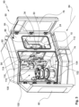
- Fig. 3 illustrates components of the setup cell 74 using an enlarged view.
- the doors 78 of the machine tool 10 and 80 of the setup cell 74 are shown open for illustrative purposes. A respective interior is visible.
- the machine tool 10 is accessible via the front 84 when the door 78 is open.
- a back opposite the front 78 is designated 86.
- the workpiece holder 30 and the tool holder 34 are mounted on the back 86 in the exemplary embodiment. This ensures good accessibility.
- the machine tool 10 is arranged with its working space 24 within the housing 64.
- the working space 24 has a loading interface 90 on the side and a setup interface 92 on an opposite side.
- the loading interface 90 can be used, for example, for an automated workpiece change.
- the setup interface 92 is used, for example, to change tools. In exemplary embodiments, the setup interface 92 is also used for changing tool devices for fixing workpieces.
- the compact installation space of the machine tool 10 and the limited working space 24 are taken into account. Furthermore, defined openings are available through which the work space 24 can be accessed for the purposes of automated workpiece changing (loading interface 90) and automated tool changing (Setup interface 92) is accessible.
- the front side 84 is not used for this or is only used to a small extent. The front 84 is still easily accessible to an operator.
- the setup interface 92 has an opening that can be closed by a door 94.
- the door 94 can be opened if necessary to release the opening of the setup interface 92.
- the door 94 is designed as a vertically movable lifting door (guillotine).
- the setup cell 74 is part of a tool changing device 100.
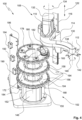
- the tool changing device 100 is based on the Figures 3 and 4 illustrated.
- the tool changing device 100 includes a staging area 102 for a tool magazine 104.
- the tool magazine 104 is a vertically oriented disc magazine.
- the staging area 102 serves to accommodate and rotate the tool magazine 104 within the setup cell 74.
- the tool magazine 104 provides a plurality or multiplicity of tools in the setup cell 74, which can be exchanged into the work space 24 in order to supply the tool holder 34 to the machine tool 10 equip.
- the tool changing device 100 further comprises a handling unit 108 with a handling robot 110.
- the task of the handling unit 108 is to transfer tools between the tool magazine 104 and the tool holder 34.
- the handling unit 108 also serves to move workpiece devices between the setup cell 74 and the work space 24 to transfer.
- the handling robot 110 points in Fig. 3 an end effector in the form of a tool gripper 112.
- the handling robot 110 includes a base 114 (see Fig. 4 ), which can be moved vertically along a lifting axis 116. Compare this with one in Fig. 3 Lift drive designated 118. The resulting lifting movement is in Fig. 4 illustrated by a double arrow labeled 122.
- the handling robot 110 also has a swivel arm 130, which has a Pivot axis 132 is pivotable, compare a curved double arrow 134 in Fig. 4 to illustrate the pivoting movement.
- the swivel arm 130 is mounted on the base 114 and can be moved via this along the lifting axis 116.
- the handling robot 110 is designed as a vertically movable horizontal articulated arm robot.
- the pivot axis 132 is oriented vertically. Accordingly, the pivot arm 130 moves along a horizontal path during the pivoting movement.
- the handling robot 110 is designed as a SCARA robot.
- the pivot arm 130 is inherently rigid and pivotally mounted on the base 114 via only a single pivot axis 132. In this way, the number of degrees of freedom required and the number of drives required can be reduced.
- the swivel arm 130 is curved in an approximately S-shape (in plan view). In this way, the swivel arm 130 with the tool gripper 112 accommodated thereon can be moved through the (open) setup interface 92 in order to exchange tools with the tool holder 34 of the machine tool 10. It goes without saying that designs with additional (particularly vertically oriented) pivot axes are also conceivable.
- the tool gripper 112 sits on an end of the swivel arm 130 facing away from the base 114.
- the tool gripper 112 can be rotated via a rotation axis 138, compare a curved double arrow 140 in Fig. 4 .
- the tool gripper 112 includes one or more gripper seats 142 for holding tools.
- the gripper seats 142 are designed approximately fork-shaped in order to hold a tool between two arms/tines.
- the tool gripper 112 is designed in particular as a multiple gripper with at least two gripper seats 142 for holding tools.
- the tool holder 112 has a total of four gripper seats 142, each of which is arranged offset by 90° around the axis of rotation 138.
- the design of the tool gripper 112 as a multiple gripper reduces the tool change times because the tool gripper 112 does not have to be moved several times between the tool magazine 104 and the tool holder 34 through the setup interface 92 in order to replace one tool on the tool holder with another.
- the staging area 102 carries the tool magazine 104.
- the tool magazine 104 sits on a pedestal 148 at the staging area 102.
- a rotary drive 150 for the tool magazine 104 is provided at the staging area 102. In this way, the tool magazine 104 can be rotated about an axis of rotation 152. This allows targeted provision of tools and takes into account the conceivable simplified design of the handling robot 110 with only one pivot axis 132.
- the tool magazine 104 has three levels 156, 158, 160 arranged one above the other.
- Each of the levels 156, 158, 160 is approximately disk-shaped or annular disk-shaped.
- the disk diameter of levels 156, 158, 160 is identical.
- the levels 156, 158, 160 each carry a plurality or multiplicity of tool positions 164.
- the tool locations 164 are distributed in a circle around the axis of rotation 152 or around a center 168 of the tool magazine 104.
- the tool magazine 104 can be specifically rotated (indexed) in order to provide a selected tool location 164 at a transfer position for exchanging tools with the tool gripper 112 of the handling robot 110.
- the handling robot 110 can be moved vertically via the lifting axis 116 in order to approach one of the levels 156, 158, 160.
- the tool magazine 104 is designed to be rigid. In other words, the planes 156, 158, 160 are rigid to one another and cannot be rotated or otherwise moved relative to one another. The levels 156, 158, 160 are firmly connected to each other via the center 168.
- the tool magazine 104 visually resembles a cake stand with shelves of the same diameter. Particularly when used for compactly designed machine tools 10, the tool magazine 104 is designed to be sufficiently compact and lightweight despite its considerable capacity. This allows the tool magazine 104 to be changed manually.
- Changing the tool magazine 104 is simplified by a handle 172 on the top 178 of the tool magazine 104. Using the handle 172, an operator can lift the tool magazine 104 and take it out of the setup cell 74 (compare Fig. 3 and Fig. 5 ) out. In this way, block setup is possible, with a large number of tools being provided in just one setup process.
- the tool magazine 104 can be changed parallel to the machining time.
- the setup interface 92 can be hermetically closed through the door 94. If the tool gripper 112 is designed as a multiple gripper, a tool change can still take place if necessary even when the tool magazine 104 is absent because the tool gripper 112 can store at least one tool.
- the tool magazine 104 serves as a background magazine, with the tool gripper 112 being designed as a multiple gripper and serving as a foreground magazine. This can further speed up tool changes and reduce overall machining time.
- the tool magazine 104 also serves to accommodate and provide at least one workpiece device 182.
- receiving locations 180 are arranged on the top 178 of the tool magazine 104, which are designed to accommodate workpiece devices 182.
- the workpiece devices 182 make it easier to pick up and fix workpieces on the workpiece holder 30 of the machine tool 10.
- a total of six receiving locations 180 are provided on the top 178 of the (upper) level 160, one of the receiving locations 180 being equipped with a workpiece device 182.
- Sensors 190, 192, 194 are also provided for detecting the occupancy status of the tool magazine 104.
- the sensors 190, 192, 194 are designed to detect the presence of a tool in one of the tool locations 164 when the tool magazine 104 is rotated and the monitored tool location 164 passes the sensor 190, 192, 194.
- the sensor 190 is used to monitor level 156.
- the sensor 192 is used for monitoring the level 158.
- the sensor 194 is used to monitor the level 160.
- a further sensor 196 is provided, which is used to record the occupancy status of the recording locations 180 on the top 178. In this way, the presence of workpiece devices 182 in the tool magazine 104 can be monitored.
- An end facing away from the top 178 of the tool magazine 104 is referred to as the lower end 184.
- Fig. 5 shows the tool magazine 104 in a state lifted from the staging area 102.
- a dashed representation additionally illustrates the state set up at the staging area 102.
- a sensor 198 is provided at the staging area 102, which detects the presence of a tool magazine 104.
- the staging area 102 provides a turntable 202 for the tool magazine 104, so that an attached tool magazine 104 can be rotated in a defined manner about the axis of rotation 152.
- the tool magazine 104 has a support surface 206 (in Fig. 5 only indicated by dashed lines), with which the tool magazine 104 can be placed on a support surface 204 of the turntable 202.
- a pin 208 is provided on the turntable 202, which ensures centering. The pin 208 protrudes through the support surface 204.
- the support surface 206 is designed in a ring shape and is adapted to the support surface 204.
- a recess 210 is provided within the support surface 206, into which the pin 208 engages when the tool magazine 104 is seated on the turntable 202.
- the tool magazine 104 is placed over the turntable 202, which protrudes like a thorn.
- the turntable 202 supports the tool magazine 104 with the support surface 204 within a central profile 212 formed in the center 168 of the tool magazine 104.
- the central profile 212 is designed approximately as a tubular profile.
- the turntable 202 projects into the central profile 212.
- a double arrow 214 illustrates a longitudinal extent of the tool magazine 104 along the axis of rotation 152.
- a double arrow 216 describes an insertion dimension for the turntable 202.
- the tool magazine 104 is therefore not only placed on the turntable 202 at its lower end 184. Rather, the turntable 202 projects into the central profile 212 by the insertion dimension 216. This increases the stability and tipping resistance of the tool magazine 104 and overall operational safety.
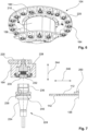
- Fig. 6 shows a partial perspective view of the tool magazine 104 from below. It can be seen that the tool positions 164 are each oriented downwards on the levels 160,158. The tool places 164 are distributed around the tubular central profile 210. The levels 158,160 each include a disk 220, which is designed approximately as an annular disk. The disks 220 cover the tool places 164 from above. At the tool locations 164, tools can be held hanging in a vertical orientation.
- Fig. 7 uses partially cut (partial) representations to illustrate the attachment of a tool 224 to a tool place 164.
- the disk 220 of one of the levels 156, 158, 160 carries the downward (hanging) oriented tool place 164.
- the tool place 164 includes a quiver 228 as well as within the quiver 228 has a pin 230 which houses a spring-loaded locking element 232.
- the tool 224 includes a tool shaft 234 with a hollow shaft 236. With the hollow shaft 236, the tool 224 can be inserted into the quiver 228 of the tool place 164 and centered.
- the locking element 232 can lock into a locking groove 238 so that the tool 224 is secured hanging in the tool place 164. In this way, recorded tools 224 in the tool magazine 104 are protected from above by the respective disk 220 and the quiver 228.
- the orientation corresponds to that of the tool 224 in the tool holder 34 of the machine tool 10, at least in exemplary embodiments.
- the tool 224 is inserted or removed via the tool gripper 112 (in Fig. 7 shown as a half section).
- the tool gripper 112 has one or more gripper seats 142.
- the gripper seat 142 can engage in a gripper groove 240 on the tool shaft 234 of the tool 224 via a horizontal movement 246.
- the horizontal movement 246 is provided via the handling robot 110, for example via a combined movement of the pivot axis 132 and the rotation axis 138, compare here Fig. 4 .
- the insertion into the tool place 164 or the removal from the tool place 164 takes place with coaxial alignment between the tool 224 and the tool place 164 via a lifting movement 244, which is provided via the lifting axis 116 of the handling robot 110.
- the tool gripper 112 has an interface 250 for recording on the swivel arm 130 of the handling robot 110.
- Fig. 8 illustrates an exemplary embodiment of a device gripper 260, which is designed to handle workpiece devices 182, which can be received at receiving locations 180 on the top 178 of the tool magazine 104.
- the workpiece device 182 has a gripper groove 262 into which a gripper seat 264 of the device gripper 260 can engage.
- the workpiece device 182 can then be lifted from its receiving position 180 and exchanged into the working space 24 of the machine tool, and vice versa, see also Fig. 3 and Fig. 4 .
- the device gripper 260 includes, in addition to the gripper seat 264 for the workpiece device 182, further gripper seats 266, which are designed to handle tools 224.
- the device gripper 260 is designed as a hybrid gripper and is designed both for handling workpiece devices 182 and for handling tools 224.
- the device gripper 260 has an interface 270 for recording on the swivel arm 130 of the handling robot 110.
- the interfaces 250, 270 of the tool gripper 112 and the device gripper 260 are designed for detachable assembly on the pivot arm 130 of the handling robot 110. In this way, the handling robot 110 can, if necessary, change the grippers 112, 260 used within the setup cell 74.
Landscapes
- Engineering & Computer Science (AREA)
- Mechanical Engineering (AREA)
- Automatic Tool Replacement In Machine Tools (AREA)
Applications Claiming Priority (1)
| Application Number | Priority Date | Filing Date | Title |
|---|---|---|---|
| DE102022123229.8A DE102022123229B4 (de) | 2022-09-12 | 2022-09-12 | Werkzeugwechselvorrichtung für eine Werkzeugmaschine und Fertigungssystem |
Publications (1)
| Publication Number | Publication Date |
|---|---|
| EP4335583A1 true EP4335583A1 (fr) | 2024-03-13 |
Family
ID=88016423
Family Applications (1)
| Application Number | Title | Priority Date | Filing Date |
|---|---|---|---|
| EP23196124.4A Pending EP4335583A1 (fr) | 2022-09-12 | 2023-09-08 | Dispositif de changement d'outil pour une machine-outil et système de fabrication |
Country Status (4)
| Country | Link |
|---|---|
| US (1) | US20240082970A1 (fr) |
| EP (1) | EP4335583A1 (fr) |
| CN (1) | CN117681022A (fr) |
| DE (1) | DE102022123229B4 (fr) |
Families Citing this family (3)
| Publication number | Priority date | Publication date | Assignee | Title |
|---|---|---|---|---|
| USD1118727S1 (en) * | 2024-02-23 | 2026-03-17 | Sanjet International Co., Ltd. | Vertical-horizontal tool changer mechanism |
| DE202024104122U1 (de) * | 2024-07-23 | 2025-11-03 | POS GmbH & Co. KG | Bearbeitungsmaschine |
| CN119501648B (zh) * | 2025-01-20 | 2025-05-09 | 宁波匹克智能科技有限公司 | 一种用于加工油压刹车器的加工设备 |
Citations (8)
| Publication number | Priority date | Publication date | Assignee | Title |
|---|---|---|---|---|
| DD250079A1 (de) * | 1986-06-23 | 1987-09-30 | Mikromat Dresden Betrieb | Werkzeugmagazin an bearbeitungszentren |
| EP0515798A1 (fr) * | 1991-05-17 | 1992-12-02 | HIRSCHMANN GmbH | Magazine pour outils et/ou pièces avec changeur |
| EP0517651A1 (fr) * | 1991-06-03 | 1992-12-09 | Erowa AG | Installation de production |
| DE29821047U1 (de) | 1998-11-25 | 1999-04-01 | Laempe, Hans Joachim, Dipl.-Ing., 79692 Raich | Werkzeugmaschinen-Anordnung mit einer Vorrichtung für einen automatischen Werkzeugwechsel |
| EP1985411A1 (fr) | 2007-04-18 | 2008-10-29 | Feinmechanik Michael Deckel GmbH & Co. KG | Agencement de machines-outils doté d'un changement de pièce et d'outil |
| US20190084102A1 (en) | 2016-04-19 | 2019-03-21 | Haute Ecole Arc | Five axis machine tool |
| EP3566808A1 (fr) * | 2017-08-10 | 2019-11-13 | Yamazaki Mazak Corporation | Machine-outil |
| EP3194114B1 (fr) * | 2014-09-19 | 2022-02-16 | HOMAG GmbH | Dispositif de préhension pour un outil d'usinage, système de stockage et procédé |
Family Cites Families (3)
| Publication number | Priority date | Publication date | Assignee | Title |
|---|---|---|---|---|
| DE102005006722A1 (de) * | 2005-02-07 | 2006-08-10 | Index-Werke Gmbh & Co. Kg Hahn & Tessky | Werkstückbearbeitungsanlage |
| DE102005028358A1 (de) * | 2005-06-18 | 2006-12-21 | Alfing Keßler Sondermaschinen GmbH | Bearbeitungsmaschinenanordnung mit Roboter und Werkzeugmagazin |
| DE102018121970A1 (de) * | 2018-09-10 | 2020-03-12 | Chiron-Werke Gmbh & Co. Kg | Werkzeugmaschine |
-
2022
- 2022-09-12 DE DE102022123229.8A patent/DE102022123229B4/de active Active
-
2023
- 2023-09-07 CN CN202311157146.2A patent/CN117681022A/zh active Pending
- 2023-09-08 EP EP23196124.4A patent/EP4335583A1/fr active Pending
- 2023-09-12 US US18/367,009 patent/US20240082970A1/en active Pending
Patent Citations (8)
| Publication number | Priority date | Publication date | Assignee | Title |
|---|---|---|---|---|
| DD250079A1 (de) * | 1986-06-23 | 1987-09-30 | Mikromat Dresden Betrieb | Werkzeugmagazin an bearbeitungszentren |
| EP0515798A1 (fr) * | 1991-05-17 | 1992-12-02 | HIRSCHMANN GmbH | Magazine pour outils et/ou pièces avec changeur |
| EP0517651A1 (fr) * | 1991-06-03 | 1992-12-09 | Erowa AG | Installation de production |
| DE29821047U1 (de) | 1998-11-25 | 1999-04-01 | Laempe, Hans Joachim, Dipl.-Ing., 79692 Raich | Werkzeugmaschinen-Anordnung mit einer Vorrichtung für einen automatischen Werkzeugwechsel |
| EP1985411A1 (fr) | 2007-04-18 | 2008-10-29 | Feinmechanik Michael Deckel GmbH & Co. KG | Agencement de machines-outils doté d'un changement de pièce et d'outil |
| EP3194114B1 (fr) * | 2014-09-19 | 2022-02-16 | HOMAG GmbH | Dispositif de préhension pour un outil d'usinage, système de stockage et procédé |
| US20190084102A1 (en) | 2016-04-19 | 2019-03-21 | Haute Ecole Arc | Five axis machine tool |
| EP3566808A1 (fr) * | 2017-08-10 | 2019-11-13 | Yamazaki Mazak Corporation | Machine-outil |
Also Published As
| Publication number | Publication date |
|---|---|
| CN117681022A (zh) | 2024-03-12 |
| DE102022123229B4 (de) | 2025-11-13 |
| DE102022123229A1 (de) | 2024-03-14 |
| US20240082970A1 (en) | 2024-03-14 |
Similar Documents
| Publication | Publication Date | Title |
|---|---|---|
| EP4335583A1 (fr) | Dispositif de changement d'outil pour une machine-outil et système de fabrication | |
| EP3147073B1 (fr) | Machine-outil, en particulier fraiseuse multi-broches | |
| EP1765550B1 (fr) | Machine-outil | |
| DE3729162C2 (fr) | ||
| EP0216261B1 (fr) | Machine-outil | |
| EP4259377A2 (fr) | Changeur d'outil | |
| EP2945776B1 (fr) | Machine-outil avec échangeur de palettes | |
| DE102020100962B4 (de) | Werkzeugmaschine | |
| DE102021113892B4 (de) | Kombinierte Transfer- und Speichervorrichtung sowie Anlage zur spanenden Fertigung | |
| EP4094884A1 (fr) | Système d'usinage et installation d'usinage par enlèvement des copeaux | |
| DE102008004851A1 (de) | Vorrichtung zum Bearbeiten, insbesondere Erodieren und Schleifen, von mit Schneiden versehenen Rotationsstücken | |
| EP1752255B1 (fr) | Tour multibroche avec manipulateur de pièces articulé | |
| EP4335585A1 (fr) | Dispositif d'évacuation de copeaux pour machine-outil et système de fabrication | |
| DE102005027785B4 (de) | Mehrachsige Drehbearbeitungsvorrichtung und Verfahren zum Drehen eines Werkstücks damit | |
| EP1736264B1 (fr) | Dispositif pour l'usinage intérieur de pièces, en particulier de carters d'engrenages différentiels | |
| DE3634018C2 (fr) | ||
| EP4190487A1 (fr) | Dispositif de changement d'outil, machine-outil et procédé de changement d'outil | |
| EP3616836B1 (fr) | Dispositif d'usinage destiné à l'usinage par enlèvement de copeaux d'une pièce à usiner | |
| DE102017127116B4 (de) | Werkzeugmaschine, Fertigungszelle sowie Verfahren zum Betreiben einer Fertigungszelle | |
| DE102021108338B4 (de) | Verfahren zur Durchführung eines Werkzeugwechsels und Wechseleinrichtung zur Durchführung des Verfahrens | |
| EP4335584A1 (fr) | Cellule de manipulation pour une machine-outil et système de fabrication | |
| DE102014112208B4 (de) | Werkzeugmaschine und Verfahren zur automatischen Bestückung | |
| EP4461458B1 (fr) | Machine-outil et procédé d'usinage de pièces | |
| EP3103582A2 (fr) | Machine d'usinage dotee d'un dispositif de transfert d'outil | |
| EP0800893B1 (fr) | Machine-outil avec une espace de travail |
Legal Events
| Date | Code | Title | Description |
|---|---|---|---|
| PUAI | Public reference made under article 153(3) epc to a published international application that has entered the european phase |
Free format text: ORIGINAL CODE: 0009012 |
|
| STAA | Information on the status of an ep patent application or granted ep patent |
Free format text: STATUS: THE APPLICATION HAS BEEN PUBLISHED |
|
| AK | Designated contracting states |
Kind code of ref document: A1 Designated state(s): AL AT BE BG CH CY CZ DE DK EE ES FI FR GB GR HR HU IE IS IT LI LT LU LV MC ME MK MT NL NO PL PT RO RS SE SI SK SM TR |
|
| STAA | Information on the status of an ep patent application or granted ep patent |
Free format text: STATUS: REQUEST FOR EXAMINATION WAS MADE |
|
| 17P | Request for examination filed |
Effective date: 20240912 |
|
| RBV | Designated contracting states (corrected) |
Designated state(s): AL AT BE BG CH CY CZ DE DK EE ES FI FR GB GR HR HU IE IS IT LI LT LU LV MC ME MK MT NL NO PL PT RO RS SE SI SK SM TR |