EP4335604A2 - Dispositif de support et de referencement de feuilles en position verticale et systeme - Google Patents
Dispositif de support et de referencement de feuilles en position verticale et systeme Download PDFInfo
- Publication number
- EP4335604A2 EP4335604A2 EP23189943.6A EP23189943A EP4335604A2 EP 4335604 A2 EP4335604 A2 EP 4335604A2 EP 23189943 A EP23189943 A EP 23189943A EP 4335604 A2 EP4335604 A2 EP 4335604A2
- Authority
- EP
- European Patent Office
- Prior art keywords
- sheet
- supporting
- along
- operating position
- unit
- Prior art date
- Legal status (The legal status is an assumption and is not a legal conclusion. Google has not performed a legal analysis and makes no representation as to the accuracy of the status listed.)
- Pending
Links
Images



Classifications
-
- B—PERFORMING OPERATIONS; TRANSPORTING
- B28—WORKING CEMENT, CLAY, OR STONE
- B28D—WORKING STONE OR STONE-LIKE MATERIALS
- B28D7/00—Accessories specially adapted for use with machines or devices of the preceding groups
- B28D7/04—Accessories specially adapted for use with machines or devices of the preceding groups for supporting or holding work or conveying or discharging work
- B28D7/046—Accessories specially adapted for use with machines or devices of the preceding groups for supporting or holding work or conveying or discharging work the supporting or holding device being of the vacuum type
-
- B—PERFORMING OPERATIONS; TRANSPORTING
- B24—GRINDING; POLISHING
- B24B—MACHINES, DEVICES, OR PROCESSES FOR GRINDING OR POLISHING; DRESSING OR CONDITIONING OF ABRADING SURFACES; FEEDING OF GRINDING, POLISHING, OR LAPPING AGENTS
- B24B41/00—Component parts such as frames, beds, carriages, headstocks
- B24B41/06—Work supports, e.g. adjustable steadies
-
- B—PERFORMING OPERATIONS; TRANSPORTING
- B24—GRINDING; POLISHING
- B24B—MACHINES, DEVICES, OR PROCESSES FOR GRINDING OR POLISHING; DRESSING OR CONDITIONING OF ABRADING SURFACES; FEEDING OF GRINDING, POLISHING, OR LAPPING AGENTS
- B24B49/00—Measuring or gauging equipment for controlling the feed movement of the grinding tool or work; Arrangements of indicating or measuring equipment, e.g. for indicating the start of the grinding operation
- B24B49/02—Measuring or gauging equipment for controlling the feed movement of the grinding tool or work; Arrangements of indicating or measuring equipment, e.g. for indicating the start of the grinding operation according to the instantaneous size and required size of the workpiece acted upon, the measuring or gauging being continuous or intermittent
- B24B49/04—Measuring or gauging equipment for controlling the feed movement of the grinding tool or work; Arrangements of indicating or measuring equipment, e.g. for indicating the start of the grinding operation according to the instantaneous size and required size of the workpiece acted upon, the measuring or gauging being continuous or intermittent involving measurement of the workpiece at the place of grinding during grinding operation
- B24B49/045—Specially adapted gauging instruments
-
- B—PERFORMING OPERATIONS; TRANSPORTING
- B24—GRINDING; POLISHING
- B24B—MACHINES, DEVICES, OR PROCESSES FOR GRINDING OR POLISHING; DRESSING OR CONDITIONING OF ABRADING SURFACES; FEEDING OF GRINDING, POLISHING, OR LAPPING AGENTS
- B24B49/00—Measuring or gauging equipment for controlling the feed movement of the grinding tool or work; Arrangements of indicating or measuring equipment, e.g. for indicating the start of the grinding operation
- B24B49/10—Measuring or gauging equipment for controlling the feed movement of the grinding tool or work; Arrangements of indicating or measuring equipment, e.g. for indicating the start of the grinding operation involving electrical means
-
- B—PERFORMING OPERATIONS; TRANSPORTING
- B24—GRINDING; POLISHING
- B24B—MACHINES, DEVICES, OR PROCESSES FOR GRINDING OR POLISHING; DRESSING OR CONDITIONING OF ABRADING SURFACES; FEEDING OF GRINDING, POLISHING, OR LAPPING AGENTS
- B24B7/00—Machines or devices designed for grinding plane surfaces on work, including polishing plane glass surfaces; Accessories therefor
- B24B7/20—Machines or devices designed for grinding plane surfaces on work, including polishing plane glass surfaces; Accessories therefor characterised by a special design with respect to properties of the material of non-metallic articles to be ground
- B24B7/22—Machines or devices designed for grinding plane surfaces on work, including polishing plane glass surfaces; Accessories therefor characterised by a special design with respect to properties of the material of non-metallic articles to be ground for grinding inorganic material, e.g. stone, ceramics, porcelain
- B24B7/24—Machines or devices designed for grinding plane surfaces on work, including polishing plane glass surfaces; Accessories therefor characterised by a special design with respect to properties of the material of non-metallic articles to be ground for grinding inorganic material, e.g. stone, ceramics, porcelain for grinding or polishing glass
- B24B7/242—Machines or devices designed for grinding plane surfaces on work, including polishing plane glass surfaces; Accessories therefor characterised by a special design with respect to properties of the material of non-metallic articles to be ground for grinding inorganic material, e.g. stone, ceramics, porcelain for grinding or polishing glass for plate glass
-
- B—PERFORMING OPERATIONS; TRANSPORTING
- B24—GRINDING; POLISHING
- B24B—MACHINES, DEVICES, OR PROCESSES FOR GRINDING OR POLISHING; DRESSING OR CONDITIONING OF ABRADING SURFACES; FEEDING OF GRINDING, POLISHING, OR LAPPING AGENTS
- B24B9/00—Machines or devices designed for grinding edges or bevels on work or for removing burrs; Accessories therefor
- B24B9/02—Machines or devices designed for grinding edges or bevels on work or for removing burrs; Accessories therefor characterised by a special design with respect to properties of materials specific to articles to be ground
- B24B9/06—Machines or devices designed for grinding edges or bevels on work or for removing burrs; Accessories therefor characterised by a special design with respect to properties of materials specific to articles to be ground of non-metallic inorganic material, e.g. stone, ceramics, porcelain
- B24B9/08—Machines or devices designed for grinding edges or bevels on work or for removing burrs; Accessories therefor characterised by a special design with respect to properties of materials specific to articles to be ground of non-metallic inorganic material, e.g. stone, ceramics, porcelain of glass
- B24B9/10—Machines or devices designed for grinding edges or bevels on work or for removing burrs; Accessories therefor characterised by a special design with respect to properties of materials specific to articles to be ground of non-metallic inorganic material, e.g. stone, ceramics, porcelain of glass of plate glass
-
- B—PERFORMING OPERATIONS; TRANSPORTING
- B28—WORKING CEMENT, CLAY, OR STONE
- B28D—WORKING STONE OR STONE-LIKE MATERIALS
- B28D7/00—Accessories specially adapted for use with machines or devices of the preceding groups
- B28D7/04—Accessories specially adapted for use with machines or devices of the preceding groups for supporting or holding work or conveying or discharging work
-
- B—PERFORMING OPERATIONS; TRANSPORTING
- B65—CONVEYING; PACKING; STORING; HANDLING THIN OR FILAMENTARY MATERIAL
- B65G—TRANSPORT OR STORAGE DEVICES, e.g. CONVEYORS FOR LOADING OR TIPPING, SHOP CONVEYOR SYSTEMS OR PNEUMATIC TUBE CONVEYORS
- B65G49/00—Conveying systems characterised by their application for specified purposes not otherwise provided for
- B65G49/05—Conveying systems characterised by their application for specified purposes not otherwise provided for for fragile or damageable materials or articles
- B65G49/06—Conveying systems characterised by their application for specified purposes not otherwise provided for for fragile or damageable materials or articles for fragile sheets, e.g. glass
- B65G49/061—Lifting, gripping, or carrying means, for one or more sheets forming independent means of transport, e.g. suction cups, transport frames
-
- B—PERFORMING OPERATIONS; TRANSPORTING
- B65—CONVEYING; PACKING; STORING; HANDLING THIN OR FILAMENTARY MATERIAL
- B65G—TRANSPORT OR STORAGE DEVICES, e.g. CONVEYORS FOR LOADING OR TIPPING, SHOP CONVEYOR SYSTEMS OR PNEUMATIC TUBE CONVEYORS
- B65G49/00—Conveying systems characterised by their application for specified purposes not otherwise provided for
- B65G49/05—Conveying systems characterised by their application for specified purposes not otherwise provided for for fragile or damageable materials or articles
- B65G49/06—Conveying systems characterised by their application for specified purposes not otherwise provided for for fragile or damageable materials or articles for fragile sheets, e.g. glass
- B65G49/067—Sheet handling, means, e.g. manipulators, devices for turning or tilting sheet glass
-
- B—PERFORMING OPERATIONS; TRANSPORTING
- B65—CONVEYING; PACKING; STORING; HANDLING THIN OR FILAMENTARY MATERIAL
- B65G—TRANSPORT OR STORAGE DEVICES, e.g. CONVEYORS FOR LOADING OR TIPPING, SHOP CONVEYOR SYSTEMS OR PNEUMATIC TUBE CONVEYORS
- B65G49/00—Conveying systems characterised by their application for specified purposes not otherwise provided for
- B65G49/05—Conveying systems characterised by their application for specified purposes not otherwise provided for for fragile or damageable materials or articles
- B65G49/06—Conveying systems characterised by their application for specified purposes not otherwise provided for for fragile or damageable materials or articles for fragile sheets, e.g. glass
- B65G49/068—Stacking or destacking devices; Means for preventing damage to stacked sheets, e.g. spaces
Definitions
- the present invention relates to a device for supporting and referencing sheets in a vertical position, for example sheets made of glass, marble, granite or other types of stone, ceramic materials or synthetic materials, and a system comprising said device.
- the vertical machines for machining sheets comprise, in short, a system for supporting and moving the sheets, kept substantially vertical, and a machining station extending vertically.
- the supporting and movement system comprises, for example, a roller and a system of suction cups.
- the sheets are supported, below, by the roller and, behind, on a frame of the machine.
- the system of suction cups picks up the sheet of the roller and moves it towards the processing station.
- the suction cups act on the rear face of the sheet for moving it and retaining it at the moment of the machining (for example shaping, grinding, polishing, drilling, milling, squaring, bevelling) in the machining station.
- the prior art vertical machines operate substantially on sheets which are rectangular in shape or which have at least one rectilinear lower edge. The sheets shaped in this way may be rested with the rectilinear edge on the rollers and then be gripped by the system of suction cups which transport them towards the processing zone, keeping them resting on the lower rollers.
- the sheet rests, with its rectilinear edge, on the roller which lowers once the sheet is gripped by the suction cups; in this way, the sheet remains suspended, retained by the suction cups only.
- the prior art vertical machines do not allow the processing of sheets which do not have at least one rectilinear edge, since they cannot be easily rested on the rollers and kept vertical, or referred relative to a work surface, as, on the other hand, occurs in the horizontal machines.
- the aim of the invention is to satisfy the above-mentioned need by providing a device and a machine which allow the support and the movement of vertical glass sheets of any geometry.
- At least the specified aim is achieved by a device for supporting and referencing vertical sheets and a machine comprising said device according to the independent claims.
- the invention relates to a device for supporting and referencing a sheet having any shape and positioned along a vertical direction.
- the sheets positioned along the vertical direction are maintained with an inclination of between 0° and 10° and preferably approximately 5° relative to the vertical direction.
- the device comprises a vertical support extending along the vertical direction.
- the device comprises a lateral reference unit, connected to the vertical support.
- the device comprises a horizontal support extending along a horizontal direction.
- the device comprises a first lower contact element, connected to the horizontal support, which comprises a first supporting element and a second lower contact element, connected to the horizontal support, which comprises a second supporting element.
- the first and second supporting elements are configured to make contact, respectively, with a first and a second lower portion of the edge of the sheet.
- the first and the second supporting elements allow the sheet to be supported in a substantially vertical position regardless of the shape of the edge of the sheet.
- the first and second supporting elements and the lateral reference unit define an orientation of the sheet as a function of the shape.
- first and second supporting elements and the lateral reference unit allow a point of origin for the sheet and an orientation of the sheet to be defined.
- the first supporting element, the second supporting element and the lateral reference unit allow an orientation of the sheet to be defined.
- the lateral reference unit comprises an electronic reading device to define a positioning of the sheet in the reference system.
- the electronic reading device may be, for example, a photocell or a direct reflective sensor.
- positioning means, in other words, the position of the sheet in the reference plane identified by the sheet.
- the lateral reference unit comprises a contact element configured to come into contact with a lateral portion of an edge of the sheet and define a positioning of the sheet.
- the vertical support comprises a vertical guide extending along the vertical direction and the lateral reference unit is movable along the vertical guide.
- the vertical support is preferably positioned perpendicularly to the horizontal support.
- the horizontal support may be fixed to a lower end of the vertical support considering the device in use, defining a frame of the device.
- the horizontal support may comprise fixing systems for fixing the supporting device to a machine tool.
- the horizontal support comprises a guide extending along the horizontal direction.
- the first and the second lower contact units are movable along the horizontal guide.
- At least one between the first and the second supporting elements is movable along the vertical direction.
- both of the supporting elements are movable along the vertical direction.
- the first lower contact element preferably comprises a first actuator for moving the first supporting element along the vertical direction.
- the second lower contact element preferably comprises a second actuator for moving the second supporting element along the vertical direction.
- the first and the second actuators may be, for example, of a mechanical, pneumatic, hydraulic or electro-mechanical type.
- At least the first supporting element is movable between an operating position at which it is positioned to allow a support of the sheet and a non-operating position at which it is positioned to determine a minimum overall size.
- the first supporting element is positioned in such a way as to guarantee a support of the sheet.
- the first supporting element is moved away from the sheet and positioned in such a way as to not interfere with any movement and/or processing tools which operate on the sheet.
- moving the first supporting element away, determining a minimum overall size prevents any interferences, during the movement of the sheet, between the first supporting element and the sheet itself.
- the first supporting element is movable between the operating position and the non-operating position by means of a rotation.
- the first supporting element is movable between the operating position and the non-operating position by means of a translation or a roto-translation.
- both the first and the second supporting elements are movable between an operating position at which they are positioned in such a way as to allow a support of the sheet and a non-operating position at which they are positioned in such a way as to determine a minimum overall size.
- the first and second supporting elements are movable between the operating position and the non-operating position by means of a rotation.
- the first and second supporting elements are movable between the operating position and the non-operating position by means of a translation or a roto-translation.
- the first and the second lateral lower contact units comprise, respectively, a third and a fourth actuator, preferably of the pneumatic type.
- the lateral contact element is movable between an operating position at which it is positioned in such a way as to allow a contact of the sheet and a non-operating position at which it is positioned in such a way as to determine a minimum overall size.
- the lateral contact element in the operating position, is positioned in such a way as to guarantee a lateral contact of the sheet.
- the lateral contact element in the non-operating position, is moved away from the sheet and positioned in such a way as to not interfere with any processing and/or transport tools which act on the sheet.
- moving the lateral contact element away, determining a minimum overall size prevents any interferences, during the movement of the sheet, between the contact element and the sheet itself.
- the lateral contact element is movable between the operating position and the non-operating position by means of a rotation.
- the lateral contact element is movable between the operating position and the non-operating position by means of a translation or a roto-translation.
- the lateral reference unit comprises a fifth actuator, preferably of the pneumatic type.
- the first and second lower contact elements and the lateral contact elements comprise, respectively, a first, a second and a third detection device configured for detecting, respectively, a position of the first supporting element, of the second supporting element and of the lateral contact element along the horizontal direction and/or along the vertical direction.
- the sensors may, for example, comprise a magnetic strip and a reading head.
- the first detection device detects a position along the horizontal direction and/or a position along the vertical direction of the first supporting element.
- the first detection device preferably comprises a first sensor configured to detect the position of the first unit, and therefore of the first supporting element, along the horizontal direction.
- the first sensor may be, for example, a reading head positioned on the first unit, which determines the position of the first unit relative to a horizontal magnetic strip positioned on the horizontal structure.
- the first detection device preferably comprises a second sensor configured to detect the position of the first supporting element along the vertical direction.
- the second sensor may comprise an encoder. Two coordinates are therefore associated with the first supporting element.
- the second detection device detects a position along the horizontal direction and/or a position along the vertical direction of the second supporting element.
- the third detection device detects a position along the vertical direction of the contact element.
- the senor Since the third contact element is not movable along the horizontal direction, relative to the vertical structure, the sensor associates only one coordinate.
- the third detection device preferably comprises a sensor configured for detecting the position of the contact element along the vertical direction.
- the sensor may comprise, for example, a reading head positioned on the third unit which determines the position of the contact element relative to a vertical magnetic strip positioned on the vertical structure.
- the invention relates to a system for machining a glass sheet.
- the system comprises a device for supporting and referencing the sheet according to any one of the above-mentioned features.
- the system comprises a machine tool which comprises:
- the machine comprises a processing and control unit.
- the processing and control unit may be in communication with the first and/or with the second actuator for moving the first and/or the second supporting element from a first position to a second position along the vertical direction.
- the processing and control unit is preferably in communication with the third and the fourth actuator of the first and second lower contact units and with the fifth actuator of the lateral reference unit.
- the processing and control unit may be configured to control the rotation of the first supporting element from the operating position to the non-operating position.
- the processing and control unit may be configured to control the rotation of the second supporting element from the operating position to the non-operating position.
- the processing and control unit may be configured to control the rotation of the contact element from the operating position to the non-operating position.
- the control unit may be in communication with the gripping suction cup of the movement system.
- the command and control unit is configured to move the griping suction cup as a function of the barycentre of the sheet and of a centre of the suction cup.
- the system may comprise a handling robot comprising a body, an arm extending from the body and a plurality of suction cups supported by the arm.
- the supporting and referencing device is located on the machine tool.
- the processing and control unit is in communication with the handling robot and is configured for controlling a movement of the arm and an actuation of the plurality of suction cups for positioning, using the handling robot, the sheet on the supporting device.
- the supporting and referencing device is positioned close to the machine.
- the processing and control unit is in communication with the robot and is configured for controlling a movement of the arm and an actuation of the plurality of suction cups for picking up the sheet from the device and positioning it directly against the suction cup of the movement device.
- the system may comprise a device for supporting the sheet positioned downstream of the machining station according to the feed direction to support the machined sheet, comprising a horizontal structure and two lower contact units configured to come into contact with a portion of lower edge.
- the invention relates to a method for orienting a sheet by means of a system for machining a sheet according to any one of the above-mentioned features, said method comprising the steps of:
- the method comprises a step of positioning a handling robot comprising a body, an arm and a plurality of suction cups.
- the step of picking up and positioning the sheet at the supporting and referencing device preferably comprises a step of picking up the sheet by means of the handling robot and releasing it at the supporting and referencing device.
- the step of positioning the oriented sheet L against the at least one gripping suction cup 53 configured for retaining the sheet L comprises a step of picking up by means of the handling robot 60 the sheet L from the supporting and referencing device 1 and releasing it against the at least one suction cup 53 of the machine tool 50.
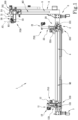
- the numeral 1 in Figure 1 denotes a device for supporting and referencing a sheet L having any predetermined shape s and positioned along a vertical direction.
- the sheet L can be, for example, a sheet made of glass, marble, granite or other types of stone, ceramic materials or synthetic materials.
- the device 1 comprises a vertical support 3 extending along the vertical direction.
- the device 1 comprises a lateral reference unit 30 connected to the vertical support 3.
- the vertical support 3 comprises a vertical guide 5 extending along the vertical direction.
- the lateral contact unit 30 is movable along the vertical guide 5.
- the device 1 comprises a vertical support 2 extending along the vertical direction.
- the device 1 comprises a first lower contact unit 10, connected to the horizontal support 2, which comprises a first supporting element 11.
- the supporting element 11 is configured to come into contact with a lower portion s1 of an edge s of the sheet L.
- the device 1 comprises a second lower contact unit 20, connected to the horizontal support 2, which comprises a second supporting element 21.
- the supporting element 21 is configured to come into contact with a lower portion s2 of an edge s of the sheet L.
- the first and the second supporting elements 11, 21 and the lateral reference unit 30 define an orientation of the sheet L as a function of said shape s.
- the first and second supporting elements 11, 21 and the unit 30 allow an origin and an orientation for the sheet to be identified for referencing the sheet.
- the lateral reference unit 30 comprises an electronic reading device 70 such as, for example, a photocell.
- the electronic reading device allows a positioning of the sheet in the reference plane to be defined.
- the lateral reference unit 30 comprises a lateral contact element 31 configured to come into contact with a lateral portion s3 of an edge s of the sheet L.
- the horizontal support 4 comprises a horizontal guide 4 extending along the horizontal direction and the lower contact units 10 and 20 are movable along the horizontal guide 4.
- the device 1 comprises coupling means 7, 8 for coupling the horizontal support 2 and/or the vertical support 3, for example, to a machine tool.
- At least one between the first and the second supporting elements 11, 21 is movable along the vertical direction.
- both the supporting elements 11 and 21 are movable along the vertical direction.
- the first lower contact element 10 comprises a first actuator 12 for moving the first supporting element 11 along the vertical direction.
- the first actuator 12 may be, for example, manual or motor-driven.
- the unit 10 may, for example, comprise a crank 12A for moving the first supporting element 11 along the vertical.
- the second lower contact element 20 comprises a second actuator 22 for moving the second supporting element 21 along the vertical direction.
- the second actuator 22 may be, for example, manual or motor-driven.
- the unit 20 may, for example, comprise a crank 22A for moving the first supporting element 21 along the vertical.
- the first and the second units 10, 20 have the same features.
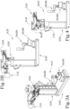
- At least the first supporting element 11 is movable between an operating position P1 at which it allows a support of the sheet and a non-operating position P2 at which the first element 11 is positioned in such a way as to determine a minimum overall size.
- the first supporting element 11 is movable between the operating position P1 and the non-operating position P2 by means of a rotation R1.
- the rotation R1 takes place about a horizontal axis A1.
- the supporting element 11 in order to pass from the operating position P1 to P2, performs a rotation substantially of 90°.
- the supporting element 11 is positioned in such a way as to guarantee a support for the sheet L.
- the supporting element 11 is positioned in such a way as to not interfere with any tools for moving or machining the sheet or with the sheet itself.
- both the supporting elements 11, 21 are movable between an operating position P1, P1' at which they are positioned in such a way as to allow a support of the sheet and a non-operating position P2, P2' at which they are positioned in such a way as to determine a minimum overall size.
- the second supporting element 21 is movable between the operating position P1' and the non-operating position P2' by means of a rotation R2.
- the rotation R2 takes place about a horizontal axis A2.
- the lateral contact element 31 is movable between an operating position P3 at which it is positioned to allow a contact of the sheet and a non-operating position P4 at which it is positioned to determine a minimum overall size.
- the contact element 31 is movable between the operating position P3 and the non-operating position P4 by means of a rotation R3.
- the rotation R3 takes place about a vertical axis A3.
- each unit 10, 20 and 30 preferably comprises a respective actuator 13, 23, 33 which allows the rotations R1, R2 and R3 of the supporting element 11, 21 and of the contact element 31.
- the actuators 13, 23 and 33 are of the pneumatic type.
- the first lower contact unit 10 comprises a first detection device 100
- the second lower contact unit 20 comprises a second detection device 200
- the lateral contact unit 30 comprises a third detection device 300.
- the first, second and third detection devices 100, 200, 300 are configured to detect a position P10, P20 and P30 along the horizontal and/or vertical direction of the first supporting element 11, of the second supporting element 21 and of the lateral reference unit 30 (and consequently of the lateral contact element 31).
- the sensors may, for example, comprise a magnetic strip and a reading head.
- the first detection device 100 comprises a sensor 101, positioned on the first unit 10, for detecting a position along the horizontal direction of the first supporting element 11.
- the first detection device 100 comprises a sensor 102, positioned on the first unit 10, for detecting a position along the vertical direction of the first supporting element 11.
- the second detection device 200 comprises a sensor 201, positioned on the second unit 20, for detecting a position along the horizontal direction of the second supporting element 21.
- the second detection device 100 comprises a sensor 202, positioned on the second unit 20, for detecting a position along the vertical direction of the second supporting element 21.
- the sensors 102 and 202 are encoders.
- the sensors 102 and 202 detect a position along the vertical direction of the first and second supporting elements 11, 21 when they are in the operating position P1, P1 '.
- the sensors 101, 201 are reading heads which determine the position of the unit 10, 20 relative to a horizontal magnetic strip M1 positioned on the horizontal structure 2.
- the third detection device 300 comprises a sensor 301, positioned on the unit 30, for detecting a position along the vertical direction of the lateral contact element 31.
- the senor 301 is a reading head which allows the position of the unit 30 to be determined relative to a vertical magnetic strip M2 positioned on the vertical structure 3.
- the invention relates to a system 500 for machining a glass sheet.
- the system 500 comprises a device 1 for supporting and referencing the sheet according to any of the above-mentioned features and a machine tool 50.
- the machine tool 50 comprises:
- the machine 50 comprises a processing and control unit U.
- the unit U is at least in communication with the first, second and third detection devices 100, 200, 300 and is configured to receive the position P10, P20, P30.
- the U unit is configured to receive: from the first detection device 100 a coordinate along the horizontal direction and a coordinate along the vertical direction of the first supporting element 11; from the second detection device 200 a coordinate along the horizontal direction and a coordinate along the vertical direction of the second supporting element 21; from the third detection device 300 a coordinate along the vertical direction of the lateral contact element 31.
- the unit U is in communication with the first and the second unit 10, 20.
- the unit U is configured to move the first and second units 10, 20 along the horizontal structure 2.
- the unit U is configured to move the first and second supporting elements 11, 21 along the horizontal direction.
- the unit U is in communication with the first actuator 12 for moving the first supporting element 11 from the position P10 to a new position P10' along the vertical direction.
- the unit U is in communication with the first actuator 12 and with the second actuator 22 for moving the first and the second supporting elements 11, 21 from the position P10, P20 to a new position P10', P20' along the vertical direction.
- the unit U is configured for moving the lateral unit 30 from the position P30 to a new position P30' along the vertical direction.
- the processing and control unit U is in communication with the actuators 13, 23, 33 and is configured for controlling the rotation R1 of the first supporting element 11, the rotation R2 of the second supporting element 21 and the rotation R3 of the contact element 31.
- the system 500 comprises a handling robot 60 which comprises a body 61, an arm 62 extending from the body and a plurality 63 of suction cups supported by the arm 62.
- the supporting device 1 is positioned on the machine tool 50, as illustrated in Figures 5 to 7 .
- the processing unit U is in communication with the handling robot 60 and is configured for controlling a movement of the arm and an actuation of the plurality 63 of suction cups for positioning, using the handling robot 60, the sheet on the supporting device 1.
- the processing and control unit is therefore in communication at least with the robot 60, with the units 10, 20, 30 of the supporting and referencing device 1 and with the machine tool 50, in particular with the at least one suction cup 53.
- the supporting device 1 is positioned close to the machine as illustrated in Figure 8 .
- the processing and control unit U is in communication with the handling robot 60 and is configured to control a movement of the arm 62 and an actuation of the plurality 63 of suction cups for picking up the sheet L from the supporting device 1 and positioning the sheet L against the suction cup 53 of the movement device 52 using the handling robot 60.
- the system 500 may comprise an unloading station 55.
- the unloading station 55 may comprise, for example, a device 56 for supporting the sheet positioned downstream of the machining station 54 along the feed direction D for supporting the machined sheet.
- the supporting device 56 comprising a horizontal structure 57 equipped with a guide and two lower contact units 58A, 58B movable along the guide, configured to define a support for the machined sheet.
- the invention relates to a method for orienting a sheet by means of a system 500 for machining a sheet according to any one of the above-mentioned features, said method comprising the steps of:
- the method comprises a step of positioning a handling robot 60 comprising a body 61, an arm 62 and a plurality 63 of suction cups.
- the step of picking up said sheet L and positioning said sheet L at the supporting and referencing device 1 preferably comprises a step of picking up by means of the handling robot 60 the sheet L and releasing it at the supporting and referencing device 1.
- the step of positioning the oriented sheet L against the at least one gripping suction cup 53 configured for retaining the sheet L comprises a step of picking up by means of the handling robot 60 the sheet L from the supporting and referencing device 1 and releasing it against the at least one suction cup 53 of the machine tool 50.
Landscapes
- Engineering & Computer Science (AREA)
- Mechanical Engineering (AREA)
- Chemical & Material Sciences (AREA)
- Ceramic Engineering (AREA)
- Inorganic Chemistry (AREA)
- Sheets, Magazines, And Separation Thereof (AREA)
- Registering Or Overturning Sheets (AREA)
Applications Claiming Priority (1)
| Application Number | Priority Date | Filing Date | Title |
|---|---|---|---|
| IT202200018441 | 2022-09-09 |
Publications (2)
| Publication Number | Publication Date |
|---|---|
| EP4335604A2 true EP4335604A2 (fr) | 2024-03-13 |
| EP4335604A3 EP4335604A3 (fr) | 2024-07-17 |
Family
ID=84331463
Family Applications (1)
| Application Number | Title | Priority Date | Filing Date |
|---|---|---|---|
| EP23189943.6A Pending EP4335604A3 (fr) | 2022-09-09 | 2023-08-07 | Dispositif de support et de referencement de feuilles en position verticale et systeme |
Country Status (1)
| Country | Link |
|---|---|
| EP (1) | EP4335604A3 (fr) |
Citations (1)
| Publication number | Priority date | Publication date | Assignee | Title |
|---|---|---|---|---|
| US7861448B2 (en) * | 2008-06-17 | 2011-01-04 | Povilaitis Darius A | Banner mounting assembly and method |
Family Cites Families (6)
| Publication number | Priority date | Publication date | Assignee | Title |
|---|---|---|---|---|
| US3184070A (en) * | 1962-11-26 | 1965-05-18 | Saint Gobain Corp | Apparatus for supporting glass sheets |
| AT399867B (de) * | 1990-01-11 | 1995-08-25 | Lisec Peter | Anlage zur herstellung von isolierglasscheiben |
| DE4234536C2 (de) * | 1992-10-14 | 1998-08-27 | Armatec Maschinentechnik Gmbh | Anlage zum Schneiden von Glasscheiben |
| AT513510B1 (de) * | 2012-10-23 | 2014-05-15 | Lisec Austria Gmbh | Vorrichtung zum Schleifen und Säumen flächiger Werkstücke |
| ITRN20130005A1 (it) * | 2013-01-31 | 2014-08-01 | Denver Spa | Macchina utensile. |
| JP2020505513A (ja) * | 2017-01-23 | 2020-02-20 | アプライド マテリアルズ インコーポレイテッドApplied Materials,Incorporated | 基板のためのホルダ |
-
2023
- 2023-08-07 EP EP23189943.6A patent/EP4335604A3/fr active Pending
Patent Citations (1)
| Publication number | Priority date | Publication date | Assignee | Title |
|---|---|---|---|---|
| US7861448B2 (en) * | 2008-06-17 | 2011-01-04 | Povilaitis Darius A | Banner mounting assembly and method |
Also Published As
| Publication number | Publication date |
|---|---|
| EP4335604A3 (fr) | 2024-07-17 |
Similar Documents
| Publication | Publication Date | Title |
|---|---|---|
| EP3460834B1 (fr) | Véhicule de transport et procédé de transport | |
| CN112770992A (zh) | 真空抓手装置、进给单元和输送扁平部件的方法 | |
| US9758311B2 (en) | Method and device for machining large sized plates in a numerical control workstation | |
| US6557689B2 (en) | Assembly for supporting and retaining glass sheets | |
| JP4244326B2 (ja) | 板状ワークの吸着ハンドおよび該吸着ハンドを用いた板状ワークの移載方法 | |
| JP5037293B2 (ja) | ワーク加工システム | |
| US20180250781A1 (en) | Autonomous production line | |
| CN110303494A (zh) | 机器人加工系统 | |
| US11919152B2 (en) | Vacuum gripper, feed unit, and method for conveying flat components | |
| JP5438747B2 (ja) | ワーク作業システム | |
| EP2318179B1 (fr) | Appareil pour centrer correctement des pièces à usiner, sur la pince de l'arbre vertical d'une machine-outil, et procédé de fonctionnement correspondant | |
| EP1270147A2 (fr) | Procédé d'ajustage d'une machine pour usiner d'une plaque de verre, et machine configurable par un tel procédé | |
| JP6702065B2 (ja) | ガラス板の製造方法およびガラス板製造装置 | |
| EP1488875A1 (fr) | Tour vertical inverté | |
| EP3257794B1 (fr) | Table de traitement de verre comportant des zones de chargement et de traitement | |
| US20200156250A1 (en) | Method for orienting two workpieces to form a joining connection and manipulator | |
| EP3253511B1 (fr) | Procédé de chargement d'ébauches dans une presse, et système | |
| EP1201612A2 (fr) | Dispositif de séparation et de manutention de feuilles de verre | |
| JP2703625B2 (ja) | 板金加工機の板材供給装置 | |
| JPH10129832A (ja) | カード状ワークの吸着反転昇降装置及び該装置を備えるカード状ワークの反転移送装置 | |
| CN219361459U (zh) | 双夹爪夹取装置 | |
| JPH07299645A (ja) | シャーラインにおけるワークの定寸送り装置 | |
| CN115246085B (zh) | 一种周边磨床刀片翻转定位装置及其控制方法 | |
| JP4103950B2 (ja) | ワークの姿勢検出方法 | |
| EP4257319B1 (fr) | Centre de travail à commande numérique pour l'usinage de plaques de verre ou de plaques en pierre naturelle ou synthétique et procédé d'usinage correspondant |
Legal Events
| Date | Code | Title | Description |
|---|---|---|---|
| PUAI | Public reference made under article 153(3) epc to a published international application that has entered the european phase |
Free format text: ORIGINAL CODE: 0009012 |
|
| STAA | Information on the status of an ep patent application or granted ep patent |
Free format text: STATUS: THE APPLICATION HAS BEEN PUBLISHED |
|
| AK | Designated contracting states |
Kind code of ref document: A2 Designated state(s): AL AT BE BG CH CY CZ DE DK EE ES FI FR GB GR HR HU IE IS IT LI LT LU LV MC ME MK MT NL NO PL PT RO RS SE SI SK SM TR |
|
| PUAL | Search report despatched |
Free format text: ORIGINAL CODE: 0009013 |
|
| AK | Designated contracting states |
Kind code of ref document: A3 Designated state(s): AL AT BE BG CH CY CZ DE DK EE ES FI FR GB GR HR HU IE IS IT LI LT LU LV MC ME MK MT NL NO PL PT RO RS SE SI SK SM TR |
|
| RIC1 | Information provided on ipc code assigned before grant |
Ipc: B24B 9/00 20060101ALI20240613BHEP Ipc: C03B 33/02 20060101ALI20240613BHEP Ipc: B65G 49/06 20060101ALI20240613BHEP Ipc: B28D 7/04 20060101AFI20240613BHEP |
|
| STAA | Information on the status of an ep patent application or granted ep patent |
Free format text: STATUS: REQUEST FOR EXAMINATION WAS MADE |
|
| 17P | Request for examination filed |
Effective date: 20250116 |
|
| STAA | Information on the status of an ep patent application or granted ep patent |
Free format text: STATUS: EXAMINATION IS IN PROGRESS |
|
| 17Q | First examination report despatched |
Effective date: 20251218 |