EP4335975B1 - Sicherheitssystem für maschinen - Google Patents
Sicherheitssystem für maschinen Download PDFInfo
- Publication number
- EP4335975B1 EP4335975B1 EP22194155.2A EP22194155A EP4335975B1 EP 4335975 B1 EP4335975 B1 EP 4335975B1 EP 22194155 A EP22194155 A EP 22194155A EP 4335975 B1 EP4335975 B1 EP 4335975B1
- Authority
- EP
- European Patent Office
- Prior art keywords
- piston
- pressure
- safety system
- state
- hydraulic
- Prior art date
- Legal status (The legal status is an assumption and is not a legal conclusion. Google has not performed a legal analysis and makes no representation as to the accuracy of the status listed.)
- Active
Links
Images


Classifications
-
- E—FIXED CONSTRUCTIONS
- E02—HYDRAULIC ENGINEERING; FOUNDATIONS; SOIL SHIFTING
- E02F—DREDGING; SOIL-SHIFTING
- E02F9/00—Component parts of dredgers or soil-shifting machines, not restricted to one of the kinds covered by groups E02F3/00 - E02F7/00
- E02F9/20—Drives; Control devices
- E02F9/22—Hydraulic or pneumatic drives
- E02F9/226—Safety arrangements, e.g. hydraulic driven fans, preventing cavitation, leakage, overheating
-
- E—FIXED CONSTRUCTIONS
- E02—HYDRAULIC ENGINEERING; FOUNDATIONS; SOIL SHIFTING
- E02F—DREDGING; SOIL-SHIFTING
- E02F3/00—Dredgers; Soil-shifting machines
- E02F3/04—Dredgers; Soil-shifting machines mechanically-driven
- E02F3/28—Dredgers; Soil-shifting machines mechanically-driven with digging tools mounted on a dipper- or bucket-arm, i.e. there is either one arm or a pair of arms, e.g. dippers, buckets
- E02F3/36—Component parts
- E02F3/3604—Devices to connect tools to arms, booms or the like
- E02F3/3609—Devices to connect tools to arms, booms or the like of the quick acting type, e.g. controlled from the operator seat
- E02F3/3663—Devices to connect tools to arms, booms or the like of the quick acting type, e.g. controlled from the operator seat hydraulically-operated
-
- E—FIXED CONSTRUCTIONS
- E02—HYDRAULIC ENGINEERING; FOUNDATIONS; SOIL SHIFTING
- E02F—DREDGING; SOIL-SHIFTING
- E02F3/00—Dredgers; Soil-shifting machines
- E02F3/04—Dredgers; Soil-shifting machines mechanically-driven
- E02F3/28—Dredgers; Soil-shifting machines mechanically-driven with digging tools mounted on a dipper- or bucket-arm, i.e. there is either one arm or a pair of arms, e.g. dippers, buckets
- E02F3/36—Component parts
- E02F3/3604—Devices to connect tools to arms, booms or the like
- E02F3/3609—Devices to connect tools to arms, booms or the like of the quick acting type, e.g. controlled from the operator seat
- E02F3/3627—Devices to connect tools to arms, booms or the like of the quick acting type, e.g. controlled from the operator seat with a hook and a longitudinal locking element
-
- E—FIXED CONSTRUCTIONS
- E02—HYDRAULIC ENGINEERING; FOUNDATIONS; SOIL SHIFTING
- E02F—DREDGING; SOIL-SHIFTING
- E02F3/00—Dredgers; Soil-shifting machines
- E02F3/04—Dredgers; Soil-shifting machines mechanically-driven
- E02F3/28—Dredgers; Soil-shifting machines mechanically-driven with digging tools mounted on a dipper- or bucket-arm, i.e. there is either one arm or a pair of arms, e.g. dippers, buckets
- E02F3/36—Component parts
- E02F3/3604—Devices to connect tools to arms, booms or the like
- E02F3/3609—Devices to connect tools to arms, booms or the like of the quick acting type, e.g. controlled from the operator seat
- E02F3/364—Devices to connect tools to arms, booms or the like of the quick acting type, e.g. controlled from the operator seat using wedges
-
- E—FIXED CONSTRUCTIONS
- E02—HYDRAULIC ENGINEERING; FOUNDATIONS; SOIL SHIFTING
- E02F—DREDGING; SOIL-SHIFTING
- E02F9/00—Component parts of dredgers or soil-shifting machines, not restricted to one of the kinds covered by groups E02F3/00 - E02F7/00
- E02F9/24—Safety devices, e.g. for preventing overload
-
- F—MECHANICAL ENGINEERING; LIGHTING; HEATING; WEAPONS; BLASTING
- F15—FLUID-PRESSURE ACTUATORS; HYDRAULICS OR PNEUMATICS IN GENERAL
- F15B—SYSTEMS ACTING BY MEANS OF FLUIDS IN GENERAL; FLUID-PRESSURE ACTUATORS, e.g. SERVOMOTORS; DETAILS OF FLUID-PRESSURE SYSTEMS, NOT OTHERWISE PROVIDED FOR
- F15B20/00—Safety arrangements for fluid actuator systems; Applications of safety devices in fluid actuator systems; Emergency measures for fluid actuator systems
- F15B20/004—Fluid pressure supply failure
-
- F—MECHANICAL ENGINEERING; LIGHTING; HEATING; WEAPONS; BLASTING
- F16—ENGINEERING ELEMENTS AND UNITS; GENERAL MEASURES FOR PRODUCING AND MAINTAINING EFFECTIVE FUNCTIONING OF MACHINES OR INSTALLATIONS; THERMAL INSULATION IN GENERAL
- F16L—PIPES; JOINTS OR FITTINGS FOR PIPES; SUPPORTS FOR PIPES, CABLES OR PROTECTIVE TUBING; MEANS FOR THERMAL INSULATION IN GENERAL
- F16L37/00—Couplings of the quick-acting type
- F16L37/56—Couplings of the quick-acting type for double-walled or multi-channel pipes or pipe assemblies
-
- G—PHYSICS
- G01—MEASURING; TESTING
- G01D—MEASURING NOT SPECIALLY ADAPTED FOR A SPECIFIC VARIABLE; ARRANGEMENTS FOR MEASURING TWO OR MORE VARIABLES NOT COVERED IN A SINGLE OTHER SUBCLASS; TARIFF METERING APPARATUS; MEASURING OR TESTING NOT OTHERWISE PROVIDED FOR
- G01D21/00—Measuring or testing not otherwise provided for
- G01D21/02—Measuring two or more variables by means not covered by a single other subclass
-
- B—PERFORMING OPERATIONS; TRANSPORTING
- B60—VEHICLES IN GENERAL
- B60Y—INDEXING SCHEME RELATING TO ASPECTS CROSS-CUTTING VEHICLE TECHNOLOGY
- B60Y2200/00—Type of vehicle
- B60Y2200/40—Special vehicles
- B60Y2200/41—Construction vehicles, e.g. graders, excavators
- B60Y2200/412—Excavators
-
- F—MECHANICAL ENGINEERING; LIGHTING; HEATING; WEAPONS; BLASTING
- F15—FLUID-PRESSURE ACTUATORS; HYDRAULICS OR PNEUMATICS IN GENERAL
- F15B—SYSTEMS ACTING BY MEANS OF FLUIDS IN GENERAL; FLUID-PRESSURE ACTUATORS, e.g. SERVOMOTORS; DETAILS OF FLUID-PRESSURE SYSTEMS, NOT OTHERWISE PROVIDED FOR
- F15B15/00—Fluid-actuated devices for displacing a member from one position to another; Gearing associated therewith
- F15B15/20—Other details, e.g. assembly with regulating devices
- F15B15/28—Means for indicating the position, e.g. end of stroke
- F15B15/2815—Position sensing, i.e. means for continuous measurement of position, e.g. LVDT
- F15B15/2838—Position sensing, i.e. means for continuous measurement of position, e.g. LVDT with out using position sensors, e.g. by volume flow measurement or pump speed
-
- F—MECHANICAL ENGINEERING; LIGHTING; HEATING; WEAPONS; BLASTING
- F15—FLUID-PRESSURE ACTUATORS; HYDRAULICS OR PNEUMATICS IN GENERAL
- F15B—SYSTEMS ACTING BY MEANS OF FLUIDS IN GENERAL; FLUID-PRESSURE ACTUATORS, e.g. SERVOMOTORS; DETAILS OF FLUID-PRESSURE SYSTEMS, NOT OTHERWISE PROVIDED FOR
- F15B20/00—Safety arrangements for fluid actuator systems; Applications of safety devices in fluid actuator systems; Emergency measures for fluid actuator systems
-
- F—MECHANICAL ENGINEERING; LIGHTING; HEATING; WEAPONS; BLASTING
- F15—FLUID-PRESSURE ACTUATORS; HYDRAULICS OR PNEUMATICS IN GENERAL
- F15B—SYSTEMS ACTING BY MEANS OF FLUIDS IN GENERAL; FLUID-PRESSURE ACTUATORS, e.g. SERVOMOTORS; DETAILS OF FLUID-PRESSURE SYSTEMS, NOT OTHERWISE PROVIDED FOR
- F15B2211/00—Circuits for servomotor systems
- F15B2211/30—Directional control
- F15B2211/305—Directional control characterised by the type of valves
- F15B2211/30525—Directional control valves, e.g. 4/3-directional control valve
-
- F—MECHANICAL ENGINEERING; LIGHTING; HEATING; WEAPONS; BLASTING
- F15—FLUID-PRESSURE ACTUATORS; HYDRAULICS OR PNEUMATICS IN GENERAL
- F15B—SYSTEMS ACTING BY MEANS OF FLUIDS IN GENERAL; FLUID-PRESSURE ACTUATORS, e.g. SERVOMOTORS; DETAILS OF FLUID-PRESSURE SYSTEMS, NOT OTHERWISE PROVIDED FOR
- F15B2211/00—Circuits for servomotor systems
- F15B2211/50—Pressure control
- F15B2211/515—Pressure control characterised by the connections of the pressure control means in the circuit
- F15B2211/5151—Pressure control characterised by the connections of the pressure control means in the circuit being connected to a pressure source and a directional control valve
-
- F—MECHANICAL ENGINEERING; LIGHTING; HEATING; WEAPONS; BLASTING
- F15—FLUID-PRESSURE ACTUATORS; HYDRAULICS OR PNEUMATICS IN GENERAL
- F15B—SYSTEMS ACTING BY MEANS OF FLUIDS IN GENERAL; FLUID-PRESSURE ACTUATORS, e.g. SERVOMOTORS; DETAILS OF FLUID-PRESSURE SYSTEMS, NOT OTHERWISE PROVIDED FOR
- F15B2211/00—Circuits for servomotor systems
- F15B2211/60—Circuit components or control therefor
- F15B2211/63—Electronic controllers
- F15B2211/6303—Electronic controllers using input signals
- F15B2211/6306—Electronic controllers using input signals representing a pressure
- F15B2211/6313—Electronic controllers using input signals representing a pressure the pressure being a load pressure
-
- F—MECHANICAL ENGINEERING; LIGHTING; HEATING; WEAPONS; BLASTING
- F15—FLUID-PRESSURE ACTUATORS; HYDRAULICS OR PNEUMATICS IN GENERAL
- F15B—SYSTEMS ACTING BY MEANS OF FLUIDS IN GENERAL; FLUID-PRESSURE ACTUATORS, e.g. SERVOMOTORS; DETAILS OF FLUID-PRESSURE SYSTEMS, NOT OTHERWISE PROVIDED FOR
- F15B2211/00—Circuits for servomotor systems
- F15B2211/70—Output members, e.g. hydraulic motors or cylinders or control therefor
- F15B2211/71—Multiple output members, e.g. multiple hydraulic motors or cylinders
- F15B2211/7114—Multiple output members, e.g. multiple hydraulic motors or cylinders with direct connection between the chambers of different actuators
- F15B2211/7128—Multiple output members, e.g. multiple hydraulic motors or cylinders with direct connection between the chambers of different actuators the chambers being connected in parallel
-
- F—MECHANICAL ENGINEERING; LIGHTING; HEATING; WEAPONS; BLASTING
- F16—ENGINEERING ELEMENTS AND UNITS; GENERAL MEASURES FOR PRODUCING AND MAINTAINING EFFECTIVE FUNCTIONING OF MACHINES OR INSTALLATIONS; THERMAL INSULATION IN GENERAL
- F16L—PIPES; JOINTS OR FITTINGS FOR PIPES; SUPPORTS FOR PIPES, CABLES OR PROTECTIVE TUBING; MEANS FOR THERMAL INSULATION IN GENERAL
- F16L2201/00—Special arrangements for pipe couplings
- F16L2201/10—Indicators for correct coupling
Definitions
- the invention relates to the field of safety systems for machines designed to detect different states of a coupling mechanism when tools are coupled to a tilt rotator or quick coupling or the like, for example for a construction machine, a forest machine or any other industrial vehicle or machine.
- the invention relates to and may be part of a hydraulic system of a machine or device.
- tool holders are used for such applications, whereby tool holders act as intermediate devices that couple to the machine in a more permanent way, for example screwed and bolted, and to various tools in a releasable way for instance using a hydraulic or pneumatic system as described herein.
- Such tool holders are typically designed to be used with the hydraulic system and/or the electric system of the machine and in many cases these tools connect the hydraulic system and/or the electric system of the machine to the hydraulic components and/or electronic components of the tool.
- the mechanical connection of such tool holders is typically established by using a hydraulic system having a coupling mechanism, whereby the coupling mechanism is coupled to at least one hydraulic cylinder.
- the locking mechanism further comprises a hook shaped element and the hydraulic cylinder is connected to an arm.
- the tool typically comprises two brackets, for example in the form of rods, arranged at a distance to one another so that the hook shaped element of the locking mechanism can engage one bracket and the arm the other bracket by extending upon movement of the hydraulic cylinder.
- brackets for example in the form of rods
- the tool typically comprises two brackets, for example in the form of rods, arranged at a distance to one another so that the hook shaped element of the locking mechanism can engage one bracket and the arm the other bracket by extending upon movement of the hydraulic cylinder.
- the extension movement of the arm errors can occur, which errors can lead to unsafe connections between tool and tool holder and therewith may risk injury of personnel or damage of equipment.
- Attempts have been made to survey the mechanical couplings between tool holder and tools as disclosed in WO 2014/058380 A1 and WO 2011/019312 A1 .
- US 2004/0244575 A1 A system for observing stroke length in hydraulic cylinders via pressure sensors is further shown in US 2004/0244575 A1 , however the pressure cannot be detected on either side of the piston since the sensors are arranged in the hydraulic system and not directly at the hydraulic cylinder with channels into the pressure chamber. This also means that the seal in US 2004/0244575 A1 does not move over the openings of the channels that are connected to pressure sensors. In addition, the US 2004/0244575 A1 does not allow to detect four different states of the safety system but only two different states. WO 2015/102120 A1 shows a safety system being able to detect a locked state.
- the present invention seeks to provide an improved safety system for a machine.
- the inventors of the present invention have discovered that it is possible to detect different states of a hydraulic cylinder versus a coupling mechanism in a tool holder or the like by using at least one pressure sensor that is measuring the pressure in a pressure chamber of the hydraulic cylinder via a first channel into the pressure chamber.
- the inventors have discovered that this is possible, if a seal device is used that can withstand high pressures and that can move over or across openings that lead into the pressure chamber of the hydraulic cylinder. The seal device moves over the opening of the channel when the piston of the hydraulic cylinder is moved for locking and unlocking a tool or the like on the tool holder.
- a second pressure sensor also directly coupled to the pressure chamber via a channel, whereby a first channel of the first pressure sensor and a second channel of the second pressure sensor and in particular openings of the first and second channels into the pressure chamber of the hydraulic cylinder are spaced apart as seen in a longitudinal direction of the hydraulic cylinder.
- a bypass channel in combination with the first pressure sensor may be used to detect various states of the coupling mechanism and the piston, respectively. The two openings of the bypass channel into the pressure chamber of the hydraulic cylinder are thereby also spaced apart longitudinally from one another and from the first channel.
- the inventors have discovered that it is possible to detected various states of the coupling mechanism in combination with a reader on a reversing valve arranged in a hydraulic system, in particular four states namely piston in locked position state, piston activated but blocked state, piston in fully retracted state and piston in fully extended state.
- a third pressure sensor arranged close to or at the hydraulic supply line of the a head side of the pressure chamber can be used to differentiate a piston fully extended state and a piston fully retracted state.
- a safety system or tool holder for a machine comprising:
- the first pressure sensor senses a pressure P1 and the second pressure sensor senses a pressure P2 and wherein a piston in locked position state is detected when: P1 ⁇ P2.
- this may help an operator or electronic system of the machine to detect when a tool is successfully and safely coupled to the tool holder.
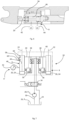
- Figure 1 schematically illustrates a tool holder 1 and a tool 2 that can be connected to one another via a coupling system 4.
- the tool holder 1 is typically coupled to a machine, for example an excavator or forestry machine or the like.
- the tool 2 or tool adapter 2 is typically arranged on a tool such as a shovel, forestry tool, cutter, compactor or the like.
- the tool 2 or tool adapter 2 is designed so that it can be coupled to the tool holder 1 automatically without manual interreference of an operator at the actual tool 2 or tool holder 1.
- the coupling of the tool holder 1 to the tool 2 is established by a coupling mechanism 4 comprising at least one hydraulic or pneumatic cylinder 8 (c.f.
- FIG. 1 the lock fingers 10 are shown in an at least partially extended state, thus with the hydraulic cylinder 8 at least partially extended.
- the hook shaped cut outs 16 are engaged first in one of the brackets 12.
- the tool adapter 2 or tool 2 can be lifted and tilted by the machine via the tool holder 1 so that the at least partially hook shaped cut outs 16' can engage the other of the pair of brackets 12, when the lock fingers 10 are retracted and typically with the help of gravity.
- the lock fingers 10 can be extended so that they lock both brackets 12 of the pair of brackets 12 securely and the tool can be used by the operator.
- the coupling does not necessarily need to be established by lifting the tool 2, tilting it on the ground or just smoothly coupling while the tool is laying on the ground may be enough to connect both the pair of brackets 12 to the tool holder 1 via the coupling mechanism 4.
- FIG. 2 illustrates, schematically, a hydraulic system 18 for a machine and shows the hydraulic cylinders 8 for the lock fingers 10 according to Fig. 1 . It consists of two hydraulic cylinders 8 each having a rod 22 and a head 24 which form the piston or plunger 20. Each rod 20 is connected with a respective lock finger 10 (c.f. figure 1 ).
- the hydraulic medium supply means comprises a tank 26, a pressurizing device 28, for example in the form of a pump or hydraulic pump, a supply line 30, and a return line 32.
- a reversing valve 34 connects the pressurizing device 28 with either the supply line 30 or the return line 32. In the shown position of the reversing valve 34, the pressurizing device 28 is connected with the supply line 30.
- the hydraulic fluid usually oil
- the hydraulic fluid is distributed to a respective branch line 36 via a respective non-return valve 38 to each of the pressure sides of the hydraulic cylinders 8.
- the return line 32 is connected with each of the return sides of the hydraulic cylinders 8.
- the branch lines 36, 40 may also be denoted as first and second hydraulic lines 36, 40.
- Figure 2 further illustrates the safety system 6 comprising a first pressure sensor 42 and a second pressure sensor 44.
- the first and second pressure sensors 42, 44 are arranged so that they communicate with a pressure chamber 46 of the hydraulic cylinder 8 via a first channel 48 for the first pressure sensor 42 and a second channel 50 for the second pressure sensor 44.
- the first and second pressure sensors 42, 44 are designed to detect the pressure in the pressure chamber 46 on either side of the head 24 of the piston 20 depending on the position of the piston and the head 24, respectively.
- various states of the coupling mechanism 4 can be detected as further explained herein.
- a first opening 54 (c.f. figure 3 ) of the first channel 48 of the first pressure sensor 42 and the second opening 56 (c.f.
- FIG 3 of the second channel 50 of the second pressure sensor 46 need to be spaced apart longitudinally, as seen along the longitudinal axis defined by the hydraulic cylinder 8.
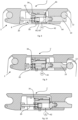
- the safety system 6 allows to detect several states of the coupling mechanism 4 and these states will now be described referring to figures 3 to 6 . It is to be noted that the safety system 6 is illustrated to be arranged on one of the pairs of hydraulic cylinders 8 in figures 2 .
- the safety system 6 may however also be installed on both cylinders 8 for redundancy and/or additional safety purposes. Further the coupling mechanism 6 may only comprise one hydraulic cylinder (not shown) or more than two hydraulic cylinders (not shown).
- Figure 2 further illustrates a processor 66 connected to the first pressure sensor 42, the second pressure sensor 44 and the reader of the reversing valve 34 or the reversing valve 34 (dashed line in figure 2 ) and/or the third pressure sensor (not shown in figure 2 ).
- FIG 3 similar reference numbers are denoting the same or similar components as figures 1 and 2 , respectively, a coupling mechanism 4 and a safety system 4 is shown.
- the coupling mechanism 4 and the piston 20, respectively is shown in a locked position.
- the lock fingers 10 lock and engage one of the brackets 12 of the tool adapter 2 or tool 2 and push it snug into the partial hook-shaped cut out 16' while the other of the brackets 12 is fully engaged in the hook shaped cut out 16 for a secure coupling of the tool 2.
- the head 24 comprises a seal device 52 designed to divide the pressure chamber 46 into two compartments and also designed to be able to move over openings 54, 56 of the first and second channels 48, 50 that connect the first and second pressure sensors 42, 44 with the pressure chamber 46.
- a seal device 52 designed to divide the pressure chamber 46 into two compartments and also designed to be able to move over openings 54, 56 of the first and second channels 48, 50 that connect the first and second pressure sensors 42, 44 with the pressure chamber 46.
- the seal device 52 can handle up to 600 bar in pressure and comprises an O-ring and seal ring.
- the O-ring and the seal ring are thereby embedded in a groove in the head 24 so that the O-ring is arranged at the or close to the bottom of the groove and the seal ring on an outer side of the O-ring.
- the O-ring can thereby move and provide space to the seal ring when the head 24 is sliding over one of the openings 54, 56.
- the O-ring is made of a softer material than the seal ring. Any other type of seal device that is suitable to slide a plurality of times over an opening in the hydraulic cylinder when the plunger or piston of the hydraulic cylinder is moving can be employed and used in the invention present herein.
- the piston in locked state can therewith being detected by P1 ⁇ P2.
- the reversing valve 34 is connected to a reader for determining a position of the reversing valve whereby the reversing valve can be moved between:
- the reversing valve 34 is in the first position connecting the head side with the supply line 30 (not shown in figure 3 ) and the pressurizing device 28 (not shown in figure 3 ) for locking the bracket 12 in the hook-shaped cut-out 16.
- the first pressure P1 will correspond to the tank pressure P res and the second pressure P2 to the system pressure P syst .
- the reversing valve 34 is however not needed to determine the piston 20 in locked state.
- the other states or position of the piston 20 are herewith described. It can however be summarized that the other states basically all refer to an incorrect locking of the brackets 12 in the hook-shaped cut-outs 16 and at least partially hooked shaped cut-outs 16'.
- Figure 4 illustrates the piston 20 in activated but blocked state in which the piston 20 is supposed to extended but the lock fingers 10 are blocked by the bracket 12 so that the first pressure P1 sensed at the first pressure sensor 42 is the same as the second pressure P2 sensed at the second pressure sensor 44 and whereby the first pressure P1 and the second pressure P2 correspond to the reservoir pressure P res (c.f. figure 2 ) provided by the pressurizing device 28.
- This state, piston 20 activated but blocked state is dangerous and correspondingly signalled to the operated for example via a display and/or acoustically and/or haptically.
- the reversing valve 34 is in the first position connecting the head side with the pressurizing device 28 and the supply line 30, respectively (c.f. figure 2 ).
- Figure 5 illustrates the piston 20 in fully extended state, whereby the sensed first pressure P1 and the sensed second pressure P2 have the same value and also correspond to the system pressure P syst and the reversing valve 34 is in the first position connecting the head side with the pressurizing device 28 and the supply line 30, respectively.
- FIG 6 illustrates the piston 20 in fully retracted state, whereby the first pressure P1 and the second pressure P2 are the same and correspond to the system pressure P syst .
- the reversing valve 34 is in the second position connecting the rod side 62 with the pressurizing device 28 and the supply line 30, respectively.
- the third pressure 70 sensor may be used to differentiate the piston fully extended state and the piston fully retracted state, whereby the piston fully retracted state is detected when P1 equals P2 and the pressure P3 sensed at the third pressure sensor 70 is smaller than P1 and P2.
- the piston fully extended state can be detected when P1 equals P2 and P2 equals P3.
- piston activated but blocked state can also be detected when P1 equals P2 but P3 is greater than P1 and P2.
- the piston locked state can be detected when P1 is smaller than P2 and P2 equals P3.
- the above examples are based on a certain distancing between the first pressure sensor 42 and the second pressure sensor 44 as illustrated.
- the invention is based on the realization that channels and their openings can be used to connect a pressure chamber 46 of a hydraulic (or pneumatic) cylinder 8 to pressure sensors 42, 44 using a seal device 52 at the head 24 of the piston, which seal device 52 is designed to glide over the openings of such channels.
- the piston in fully extended state, the piston in fully retracted state and the piston activated but blocked state may be identified as a false and the piston in locked position state may be identified as true by the processor 66.
- Corresponding visual, haptic and/or acoustic signals may be addressed to the operator of the machine.
- FIG. 7 illustrates a similar hydraulic system 18' as figure 2 with similar or same components being denoted with the same reference numbers.
- the functionality and description and components referring to figure 2 apply also for the illustration of figure 7 with the difference in the safety system 6'.
- the difference between the safety system 6' according to figure 7 and the safety system 6 according to figure 2 is that the safety system 6' illustrated in figure 7 comprises a bypass channel 58 instead of the second pressure sensor.
- the bypass channel 58 or bypass 58 is designed as a U-shaped bridge connection that has two openings 60, 60' into the pressure chamber 46 of the hydraulic cylinder 8.
- the openings 60, 60' are spaced apart as seen in a longitudinal direction of the hydraulic cylinder 8 so that they can bridge the seal device 52 in a certain position of the piston 20.
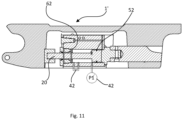
- the bypass channel can be used to determine the states of the piston 20 as described in relation to figures 8 to 11 . Again in order for the bypass channel 58 to function properly a seal device 52 as previously described needs to be installed, which seal device 52 can move across the openings 60, 60' of the bypass channel 58 and the opening of the channel connecting the first pressure sensor 42 with the pressure chamber 46.
- Figure 8 illustrates the tool holder 1' and the tool 2 or tool adapter 2 whereby the piston 20 is in the locked state in which the lock fingers 10 securely engage one of the brackets 12.
- the bypass 58 channel or bypass 58 is arranged at a distance of the first pressure sensor 42 as seen along the longitudinal direction of the hydraulic cylinder 8.
- the bypass channel 58 has two openings 60, 60' into the pressure chamber 46 of the hydraulic cylinder 8.
- the bypass channel 58 is arranged closer to the rod side 62 of the hydraulic cylinder 8 while the first pressure sensor 42 is arranged closer to the head side 64 in the embodiment shown in figures 7 to 11 .
- the bypass 58 is arranged so that it bridges the seal device 52 in the piston fully extended state (shown in figure 10 ).
- a value for a limited pressure P1 limit is defined, whereby P1 limit is determined in relation to a diameter of the bypass channel and whereby the system pressure P syst being provided by the pressurizing device 28 is always greater than P1 limit and whereby a reservoir pressure P res present in the hydraulic fluid reservoir or tank 26 is always lower than P1 limit .
- the piston 20 is in the locked state, which can be detected when the sensed pressure P1 sensed by the first pressure sensor 42 is higher than P1 limit .
- the reversing valve 34 is in the first position in which the head side 64 is connected with the pressurizing device 28 and the supply line 30, respectively.
- Figure 9 illustrates the piston 20 in the activated but blocked state, thus when the lock fingers 10 try to extend due to the pressure from the piston 20 and the hydraulic system 18', respectively, but are blocked by the bracket 12.
- This piston 20 activated but blocked state can be detected when the sensed pressure P1 at the first pressure sensor 42 is lower than P1 limit and wherein the sensed pressure P1 is equal to the reservoir pressure P res .
- the reverse valve 34 is thereby in the first position connecting the head side 64 to the supply line 30. Again, the reverse valve 34 position is not needed to detect piston 20 in the activated but blocked position.
- Figure 10 illustrates the piston 20 in the fully extended state, which can be detected when the sensed pressure P1 sensed by the first pressure sensor 42 is lower than P1 limit but higher than the reservoir pressure P res .
- the reversing valve 34 is in the first position connecting the head side 34 with the supply line 30. The reversing valve 34 position is not needed to determine the piston 20 fully extended state.
- figure 11 shows the piston 20 in fully retracted state, which can be detected when the sensed pressure P1, sensed by the first pressure sensor 42, is higher than P1 limit and when the reversing valve 34 is in the second position connecting the rod side 62 with the supply line 30 (not shown).
Landscapes
- Engineering & Computer Science (AREA)
- General Engineering & Computer Science (AREA)
- Mechanical Engineering (AREA)
- Mining & Mineral Resources (AREA)
- Civil Engineering (AREA)
- Structural Engineering (AREA)
- Physics & Mathematics (AREA)
- Chemical & Material Sciences (AREA)
- Analytical Chemistry (AREA)
- Fluid Mechanics (AREA)
- General Physics & Mathematics (AREA)
- Fluid-Pressure Circuits (AREA)
- Auxiliary Devices For Machine Tools (AREA)
- Shovels (AREA)
- Actuator (AREA)
Claims (14)
- Sicherheitssystem (6) für eine Maschine, umfassend:eine Druckvorrichtung (28);mindestens einen Hydraulikzylinder (8), der mit einem Kupplungsmechanismus (4) gekoppelt ist, wobei der mindestens eine Hydraulikzylinder (8) eine Druckkammer (46) und einen Kolben (20) umfasst, der einen Kopf (22) und eine Stange (24) aufweist, wobei der Kolben (20) entlang einer Längsrichtung des Hydraulikzylinders (8) beweglich ist;einen ersten Drucksensor (42) und einen zweiten Drucksensor (44), wobei der erste und der zweite Drucksensor (42, 44) dazu ausgestaltet sind, den Druck innerhalb der Druckkammer (46) über einen ersten Kanal (48) und einen zweiten Kanal (50) zu messen, die eine erste und eine zweite Öffnung (54, 56) aufweisen, wobei sich der erste und der zweite Kanal (48, 50) beide in die Druckkammer (46) erstrecken, wobei die erste Öffnung (54) und der zweite Kanal (56) voneinander beabstandet sind, wie in der Längsrichtung des mindestens einen Hydraulikzylinders (8) gesehen;eine Dichtungsvorrichtung (52), die in Umfangsrichtung um den Kopf (22) des Kolbens (24) angeordnet ist;ein hydraulisches System (18), das fluidisch mit einer Kopfseite (64) und einer Stangenseite (62) des mindestens einen Hydraulikzylinders (8) verbunden ist, wobei das Hydrauliksystem (18) fluidisch mit einem hydraulischen Fluidbehälter (26) und der Druckvorrichtung (28) verbunden ist;dadurch gekennzeichnet, dassdie Dichtungsvorrichtung (52) ausgestaltet ist, um sich eine Vielzahl von Malen über die erste und zweite Öffnung (54, 56) zu bewegen, und wobei mindestens ein Zustand des Sicherheitssystems über den ersten und zweiten Drucksensor (42, 44) detektiert werden kann, nämlich ein Kolben in verriegeltem Zustand.
- Sicherheitssystem nach Anspruch 1, wobei der erste Drucksensor (42) einen Druck P1 und der zweite Drucksensor (44) einen Druck P2 erfasst und wobei der Kolben in dem verriegelten Zustand detektiert wird, wenn: P1<P2.
- Sicherheitssystem nach Anspruch 1 oder 2, wobei der Fluidbehälter (26) einen Tankdruck Pres aufweist, der niedriger ist als ein von der Druckvorrichtung (28) erzeugter Druck, und wobei ein aktivierter aber blockierter Zustand des Kolbens detektiert wird, wenn: P1 = P2 = Pres.
- Sicherheitssystem nach einem der Ansprüche 1 bis 3, wobei die Druckvorrichtung einen Systemdruck Psyst bereitstellt, der höher ist als Pres und wobei ein vollständig eingefahrener Kolben und ein vollständig ausgefahrener Kolben detektiert werden können, wenn P1=P2=Psyst.
- Sicherheitssystem nach einem der vorhergehenden Ansprüche, wobei das Hydrauliksystem (18) ferner ein Umschaltventil (34) umfasst, das mit einem Lesegerät verbunden ist, um eine Position des Umschaltventils (34) zu bestimmen, wobei das Umschaltventil (34) zwischen Folgendem bewegt werden kann:
einer ersten Position, in der das Hydrauliksystem (18) die Kopfseite (64) mit der Druckvorrichtung (28) und die Stangenseite (62) mit dem Hydraulikfluidbehälter (26) verbindet und:
einer zweiten Position, in der das Hydrauliksystem (18) die Stangenseite (62) mit der Druckvorrichtung (28) und die Kopfseite (64) mit dem Hydraulikfluidbehälter (26) verbindet, wobei das Umschaltventil (34) und das Lesegerät die Unterscheidung zwischen dem Kolben in vollständig ausgefahrenem Zustand und dem Kolben in vollständig eingefahrenem Zustand ermöglichen. - Sicherheitssystem nach Anspruch 5, wobei der Kolben in vollständig eingefahrenem Zustand detektiert wird, wenn: P1 = P2 und wenn sich das Umschaltventil (34) in der zweiten Position befindet.
- Sicherheitssystem nach Anspruch 5, wobei der Kolben in vollständig ausgefahrenem Zustand detektiert wird, wenn: P1 = P2 und wenn sich das Umschaltventil (34) in der ersten Position befindet.
- Sicherheitssystem nach einem der Ansprüche 1 bis 3, wobei das Hydrauliksystem einen dritten Drucksensor zum Erfassen eines Drucks P3 umfasst, wobei der dritte Drucksensor an der oder zumindest nahe der Kopfseite (64) angeordnet ist, wobei der dritte Drucksensor zur Detektion der Unterscheidung des Kolbens in dem vollständig ausgefahrenen Zustand und des Kolbens in dem vollständig eingefahrenen Zustand verwendet wird.
- Sicherheitssystem nach Anspruch 8, wobei der Kolben in vollständig eingefahrenem Zustand detektiert wird, wenn: P1=P2 und P3< P2, P1.
- Sicherheitssystem nach Anspruch 8, wobei der Kolben in vollständig ausgefahrenem Zustand detektiert wird, wenn: P1=P2=P3.
- Sicherheitssystem nach Anspruch 8, wobei der aktivierte Kolben aber blockierte Zustand ferner unter Verwendung des dritten Drucksensors verifiziert werden kann, wenn P1=P2 und P3>P1,P2.
- Sicherheit nach Anspruch 8, wobei die Druckvorrichtung (28) einen Systemdruck Psyst bereitstellt, der höher ist als Pres und wobei P1=P2=P3=Psyst, wenn sich der Kolben in dem vollständig ausgefahrenen Zustand befindet.
- Sicherheitssystem nach einem der vorhergehenden Ansprüche, wobei das Sicherheitssystem zwei oder mehr Hydraulikzylinder (8) umfasst.
- Sicherheitssystem nach einem der vorhergehenden Ansprüche 4 bis 13, ferner umfassend einen Prozessor, der mit dem ersten Drucksensor (42), dem zweiten Drucksensor (44) und dem Lesegerät des Umschaltventils (34) und/oder dem dritten Drucksensor verbunden ist, wobei der Kolben in dem vollständig ausgefahrenen Zustand, der Kolben in dem vollständig eingefahrenen Zustand und der Kolben in dem aktivierten aber blockierten Zustand als gefälscht identifiziert werden und wobei der Kolben in der verriegelten Position durch den Prozessor (66) als wahr identifiziert wird.
Priority Applications (5)
| Application Number | Priority Date | Filing Date | Title |
|---|---|---|---|
| EP22194155.2A EP4335975B1 (de) | 2022-09-06 | 2022-09-06 | Sicherheitssystem für maschinen |
| KR1020230111956A KR20240034117A (ko) | 2022-09-06 | 2023-08-25 | 기계용 안전 시스템 |
| CA3211139A CA3211139A1 (en) | 2022-09-06 | 2023-09-01 | Safety system for machine |
| US18/242,354 US12601150B2 (en) | 2022-09-06 | 2023-09-05 | Safety system for machine |
| JP2023143579A JP2024037171A (ja) | 2022-09-06 | 2023-09-05 | 機械用の安全システム |
Applications Claiming Priority (1)
| Application Number | Priority Date | Filing Date | Title |
|---|---|---|---|
| EP22194155.2A EP4335975B1 (de) | 2022-09-06 | 2022-09-06 | Sicherheitssystem für maschinen |
Publications (3)
| Publication Number | Publication Date |
|---|---|
| EP4335975A1 EP4335975A1 (de) | 2024-03-13 |
| EP4335975B1 true EP4335975B1 (de) | 2025-03-12 |
| EP4335975C0 EP4335975C0 (de) | 2025-03-12 |
Family
ID=83228851
Family Applications (1)
| Application Number | Title | Priority Date | Filing Date |
|---|---|---|---|
| EP22194155.2A Active EP4335975B1 (de) | 2022-09-06 | 2022-09-06 | Sicherheitssystem für maschinen |
Country Status (5)
| Country | Link |
|---|---|
| US (1) | US12601150B2 (de) |
| EP (1) | EP4335975B1 (de) |
| JP (1) | JP2024037171A (de) |
| KR (1) | KR20240034117A (de) |
| CA (1) | CA3211139A1 (de) |
Family Cites Families (8)
| Publication number | Priority date | Publication date | Assignee | Title |
|---|---|---|---|---|
| JP2591942Y2 (ja) * | 1993-01-20 | 1999-03-10 | 油谷重工株式会社 | ピン装置 |
| US7047866B2 (en) | 2003-01-31 | 2006-05-23 | Jrb Attachments, Llc | Electrical and hydraulic control system for attachment coupling system |
| SE534020C2 (sv) | 2009-08-11 | 2011-04-05 | Oilquick Ab | Redskapsfäste med hydraulkontrollerad låsfunktion |
| GB2474572B (en) * | 2009-10-16 | 2014-11-26 | Hill Engineering Ltd | Control system for a hydraulic coupler |
| EP2909380A1 (de) | 2012-10-08 | 2015-08-26 | Rototilt Group AB | Vorrichtung zum verbinden einer vorrichtung/eines werkzeugs und verfahren dafür |
| WO2015102120A1 (ko) * | 2013-12-30 | 2015-07-09 | 볼보 컨스트럭션 이큅먼트 에이비 | 유압제어장치 및 이를 구비한 건설기계 |
| JP6529836B2 (ja) * | 2015-06-24 | 2019-06-12 | 株式会社神戸製鋼所 | 油圧式駆動装置およびその制御方法 |
| DE102015015809A1 (de) * | 2015-12-07 | 2017-06-08 | Liebherr-Hydraulikbagger Gmbh | Ventileinheit für Schnellwechsler sowie Schnellwechselsystem |
-
2022
- 2022-09-06 EP EP22194155.2A patent/EP4335975B1/de active Active
-
2023
- 2023-08-25 KR KR1020230111956A patent/KR20240034117A/ko active Pending
- 2023-09-01 CA CA3211139A patent/CA3211139A1/en active Pending
- 2023-09-05 US US18/242,354 patent/US12601150B2/en active Active
- 2023-09-05 JP JP2023143579A patent/JP2024037171A/ja active Pending
Also Published As
| Publication number | Publication date |
|---|---|
| US20240076853A1 (en) | 2024-03-07 |
| KR20240034117A (ko) | 2024-03-13 |
| JP2024037171A (ja) | 2024-03-18 |
| US12601150B2 (en) | 2026-04-14 |
| EP4335975C0 (de) | 2025-03-12 |
| EP4335975A1 (de) | 2024-03-13 |
| CA3211139A1 (en) | 2024-03-06 |
Similar Documents
| Publication | Publication Date | Title |
|---|---|---|
| JP5537659B2 (ja) | 油圧制御ロック機能を有する工具アタッチメント | |
| EP3680393B1 (de) | Koppler mit netzanschlusssystem | |
| KR102431297B1 (ko) | 파일럿 신호를 대안적 하중-감지 신호로서 이용하도록 구성된 수압 제어 밸브 | |
| WO2018056841A1 (en) | Quick hitch coupler | |
| CN103154382B (zh) | 联接配置 | |
| NO160222B (no) | Hurtigkobling for verktoey. | |
| CN103189572B (zh) | 联接配置 | |
| EP2426270A2 (de) | Kupplungsanordnung | |
| CN103154381B (zh) | 联接配置 | |
| EP4335975B1 (de) | Sicherheitssystem für maschinen | |
| US20140308061A1 (en) | Method and System for Detecting Engagement with a Work Tool Accessory | |
| CN104870836B (zh) | 电动液压阀门的故障隔离和恢复程序 | |
| EP2573279B1 (de) | Baggerkopplung mit Hydraulikkolben | |
| CN103154383B (zh) | 联接配置 | |
| CA2631107C (en) | Safety device for hydraulic hitch assembly | |
| US20260098392A1 (en) | Tiltrotator arrangement including a tiltrotator and a valve arrangement | |
| US20160003267A1 (en) | Electronic Control of Actuator Force and Torque with an Independent Metering Valve | |
| AU2024203635B2 (en) | Vacuum lifting device and system | |
| SE539072C2 (sv) | System hos redskapsfästen för att kontrollera dess låsregelsposition | |
| KR20090071168A (ko) | 굴삭기용 유압장치 | |
| JP2005146567A (ja) | クレーン仕様の油圧ショベル。 | |
| WO2024170679A1 (en) | A coupling system | |
| CN119301328A (zh) | 用于具有液压负载的移动式作业机械的阀装置 | |
| CA3024639A1 (en) | Indicator system for couplers |
Legal Events
| Date | Code | Title | Description |
|---|---|---|---|
| PUAI | Public reference made under article 153(3) epc to a published international application that has entered the european phase |
Free format text: ORIGINAL CODE: 0009012 |
|
| STAA | Information on the status of an ep patent application or granted ep patent |
Free format text: STATUS: THE APPLICATION HAS BEEN PUBLISHED |
|
| AK | Designated contracting states |
Kind code of ref document: A1 Designated state(s): AL AT BE BG CH CY CZ DE DK EE ES FI FR GB GR HR HU IE IS IT LI LT LU LV MC MK MT NL NO PL PT RO RS SE SI SK SM TR |
|
| STAA | Information on the status of an ep patent application or granted ep patent |
Free format text: STATUS: REQUEST FOR EXAMINATION WAS MADE |
|
| 17P | Request for examination filed |
Effective date: 20240821 |
|
| RBV | Designated contracting states (corrected) |
Designated state(s): AL AT BE BG CH CY CZ DE DK EE ES FI FR GB GR HR HU IE IS IT LI LT LU LV MC MK MT NL NO PL PT RO RS SE SI SK SM TR |
|
| GRAP | Despatch of communication of intention to grant a patent |
Free format text: ORIGINAL CODE: EPIDOSNIGR1 |
|
| STAA | Information on the status of an ep patent application or granted ep patent |
Free format text: STATUS: GRANT OF PATENT IS INTENDED |
|
| INTG | Intention to grant announced |
Effective date: 20241009 |
|
| GRAS | Grant fee paid |
Free format text: ORIGINAL CODE: EPIDOSNIGR3 |
|
| GRAA | (expected) grant |
Free format text: ORIGINAL CODE: 0009210 |
|
| STAA | Information on the status of an ep patent application or granted ep patent |
Free format text: STATUS: THE PATENT HAS BEEN GRANTED |
|
| AK | Designated contracting states |
Kind code of ref document: B1 Designated state(s): AL AT BE BG CH CY CZ DE DK EE ES FI FR GB GR HR HU IE IS IT LI LT LU LV MC MK MT NL NO PL PT RO RS SE SI SK SM TR |
|
| REG | Reference to a national code |
Ref country code: GB Ref legal event code: FG4D |
|
| REG | Reference to a national code |
Ref country code: CH Ref legal event code: EP |
|
| REG | Reference to a national code |
Ref country code: DE Ref legal event code: R096 Ref document number: 602022011658 Country of ref document: DE |
|
| REG | Reference to a national code |
Ref country code: IE Ref legal event code: FG4D |
|
| U01 | Request for unitary effect filed |
Effective date: 20250326 |
|
| U07 | Unitary effect registered |
Designated state(s): AT BE BG DE DK EE FI FR IT LT LU LV MT NL PT RO SE SI Effective date: 20250402 |
|
| PG25 | Lapsed in a contracting state [announced via postgrant information from national office to epo] |
Ref country code: RS Free format text: LAPSE BECAUSE OF FAILURE TO SUBMIT A TRANSLATION OF THE DESCRIPTION OR TO PAY THE FEE WITHIN THE PRESCRIBED TIME-LIMIT Effective date: 20250612 |
|
| PG25 | Lapsed in a contracting state [announced via postgrant information from national office to epo] |
Ref country code: ES Free format text: LAPSE BECAUSE OF FAILURE TO SUBMIT A TRANSLATION OF THE DESCRIPTION OR TO PAY THE FEE WITHIN THE PRESCRIBED TIME-LIMIT Effective date: 20250312 |
|
| PG25 | Lapsed in a contracting state [announced via postgrant information from national office to epo] |
Ref country code: NO Free format text: LAPSE BECAUSE OF FAILURE TO SUBMIT A TRANSLATION OF THE DESCRIPTION OR TO PAY THE FEE WITHIN THE PRESCRIBED TIME-LIMIT Effective date: 20250612 |
|
| PG25 | Lapsed in a contracting state [announced via postgrant information from national office to epo] |
Ref country code: HR Free format text: LAPSE BECAUSE OF FAILURE TO SUBMIT A TRANSLATION OF THE DESCRIPTION OR TO PAY THE FEE WITHIN THE PRESCRIBED TIME-LIMIT Effective date: 20250312 |
|
| PG25 | Lapsed in a contracting state [announced via postgrant information from national office to epo] |
Ref country code: GR Free format text: LAPSE BECAUSE OF FAILURE TO SUBMIT A TRANSLATION OF THE DESCRIPTION OR TO PAY THE FEE WITHIN THE PRESCRIBED TIME-LIMIT Effective date: 20250613 |
|
| PG25 | Lapsed in a contracting state [announced via postgrant information from national office to epo] |
Ref country code: SM Free format text: LAPSE BECAUSE OF FAILURE TO SUBMIT A TRANSLATION OF THE DESCRIPTION OR TO PAY THE FEE WITHIN THE PRESCRIBED TIME-LIMIT Effective date: 20250312 |
|
| PG25 | Lapsed in a contracting state [announced via postgrant information from national office to epo] |
Ref country code: PL Free format text: LAPSE BECAUSE OF FAILURE TO SUBMIT A TRANSLATION OF THE DESCRIPTION OR TO PAY THE FEE WITHIN THE PRESCRIBED TIME-LIMIT Effective date: 20250312 |
|
| PG25 | Lapsed in a contracting state [announced via postgrant information from national office to epo] |
Ref country code: CZ Free format text: LAPSE BECAUSE OF FAILURE TO SUBMIT A TRANSLATION OF THE DESCRIPTION OR TO PAY THE FEE WITHIN THE PRESCRIBED TIME-LIMIT Effective date: 20250312 |
|
| U20 | Renewal fee for the european patent with unitary effect paid |
Year of fee payment: 4 Effective date: 20250916 |
|
| PG25 | Lapsed in a contracting state [announced via postgrant information from national office to epo] |
Ref country code: SK Free format text: LAPSE BECAUSE OF FAILURE TO SUBMIT A TRANSLATION OF THE DESCRIPTION OR TO PAY THE FEE WITHIN THE PRESCRIBED TIME-LIMIT Effective date: 20250312 |
|
| PG25 | Lapsed in a contracting state [announced via postgrant information from national office to epo] |
Ref country code: IS Free format text: LAPSE BECAUSE OF FAILURE TO SUBMIT A TRANSLATION OF THE DESCRIPTION OR TO PAY THE FEE WITHIN THE PRESCRIBED TIME-LIMIT Effective date: 20250712 |
|
| PLBE | No opposition filed within time limit |
Free format text: ORIGINAL CODE: 0009261 |
|
| STAA | Information on the status of an ep patent application or granted ep patent |
Free format text: STATUS: NO OPPOSITION FILED WITHIN TIME LIMIT |
|
| REG | Reference to a national code |
Ref country code: CH Ref legal event code: L10 Free format text: ST27 STATUS EVENT CODE: U-0-0-L10-L00 (AS PROVIDED BY THE NATIONAL OFFICE) Effective date: 20260121 |
|
| 26N | No opposition filed |
Effective date: 20251215 |