EP4335984A1 - Siphon et toilettes de séparation dotées d'un siphon - Google Patents
Siphon et toilettes de séparation dotées d'un siphon Download PDFInfo
- Publication number
- EP4335984A1 EP4335984A1 EP23191879.8A EP23191879A EP4335984A1 EP 4335984 A1 EP4335984 A1 EP 4335984A1 EP 23191879 A EP23191879 A EP 23191879A EP 4335984 A1 EP4335984 A1 EP 4335984A1
- Authority
- EP
- European Patent Office
- Prior art keywords
- floating body
- odor trap
- trap according
- drain opening
- opening
- Prior art date
- Legal status (The legal status is an assumption and is not a legal conclusion. Google has not performed a legal analysis and makes no representation as to the accuracy of the status listed.)
- Granted
Links
Images

Classifications
-
- E—FIXED CONSTRUCTIONS
- E03—WATER SUPPLY; SEWERAGE
- E03D—WATER-CLOSETS OR URINALS WITH FLUSHING DEVICES; FLUSHING VALVES THEREFOR
- E03D13/00—Urinals ; Means for connecting the urinal to the flushing pipe and the wastepipe; Splashing shields for urinals
- E03D13/007—Waterless or low-flush urinals; Accessories therefor
-
- A—HUMAN NECESSITIES
- A47—FURNITURE; DOMESTIC ARTICLES OR APPLIANCES; COFFEE MILLS; SPICE MILLS; SUCTION CLEANERS IN GENERAL
- A47K—SANITARY EQUIPMENT; ACCESSORIES THEREFOR, e.g. TOILET ACCESSORIES
- A47K11/00—Closets without flushing; Urinals without flushing; Chamber pots; Chairs with toilet conveniences or specially adapted for use with toilets
- A47K11/02—Dry closets, e.g. incinerator closets
-
- E—FIXED CONSTRUCTIONS
- E03—WATER SUPPLY; SEWERAGE
- E03C—DOMESTIC PLUMBING INSTALLATIONS FOR FRESH WATER OR WASTE WATER; SINKS
- E03C1/00—Domestic plumbing installations for fresh water or waste water; Sinks
- E03C1/12—Plumbing installations for waste water; Basins or fountains connected thereto; Sinks
- E03C1/28—Odour seals
- E03C1/281—Odour seals using other sealants than water
-
- E—FIXED CONSTRUCTIONS
- E03—WATER SUPPLY; SEWERAGE
- E03D—WATER-CLOSETS OR URINALS WITH FLUSHING DEVICES; FLUSHING VALVES THEREFOR
- E03D5/00—Special constructions of flushing devices, e.g. closed flushing system
- E03D5/012—Special constructions of flushing devices, e.g. closed flushing system combined with movable closure elements in the bowl outlet
- E03D5/014—Special constructions of flushing devices, e.g. closed flushing system combined with movable closure elements in the bowl outlet with devices for separate removal of liquids and solids
Definitions
- the invention relates to an odor trap, in particular for a separating toilet, with a closure body which has a wall delimiting an interior and which has a drain opening in its lower region, which can be closed by a floating body arranged in the interior of the closure body.
- Separating toilets in which urine and faeces can be collected and disposed of separately, are becoming increasingly popular, especially in camping areas.
- urine collection containers are usually provided in the separation toilets.
- the Container cap has a hole.
- urine can escape from the opening in the container closure.
- odors and moisture escape.
- valve device which has a funnel with a drain opening and a valve insert.
- the valve insert is z. B. designed as a hollow sphere and can close the drain opening in a substantially vapor-tight manner when at rest.
- the valve insert lifts due to its float properties and reveals the drain opening.
- the functionality of this valve device is limited by the fact that ventilation of the collecting container is not provided and must even be avoided in order to allow the liquid level in a dip tube to rise as a level indicator.
- the object of the present invention is to provide an odor trap that enables trouble-free and reliable filling of a container.
- an odor trap in particular for a separating toilet, with a closure body which has a wall delimiting an interior space and which has a drain opening in its lower region, which is through a in the interior of the Closing body arranged floating body can be closed, with a ventilation opening separate from the drain opening being provided above the drain opening. Because the ventilation opening is provided in the odor trap itself, the container on which the odor trap is placed can itself be designed without a ventilation opening. This means that no liquid can escape from the container via the ventilation opening if the container is closed with a lid and transported after removing the odor trap.
- At least two openings at different heights can be closed by just one floating body.
- the drain opening and the ventilation opening are closed at the same time by the floating body when the floating body is in a closed position.
- both the ventilation opening and the drainage opening can be closed by the floating body when there is no liquid. In this state, no air, vapors or gases can escape from the container on which the odor trap is arranged.
- the ventilation opening is preferably located approximately at the level of the widest point of the floating body in its closed position. This allows the greatest possible distance between the ventilation opening and the drain opening to be achieved and yet both openings can be closed in a closed position by the floating body.
- More than one ventilation opening can be provided, in particular two or three ventilation openings can be provided.
- the ventilation openings can have a diameter in the range 2 - 4 mm, preferably in the range 2.5 - 3 mm.
- the floating body can be spherical. Both the floating body itself and the closure body adapted to it can be manufactured particularly easily using this measure.
- a guide for the floating body can be provided on the wall. This makes it possible to control how the floating body moves when there is liquid or the floating body is moved upwards by liquid.
- the guide is designed like a bar.
- the floating body can be kept at a distance from the rest of the wall by means of a web-like guide, so that liquid can flow downwards between the floating body and the wall.
- the guide can be formed in one piece with the closure body.
- the closure body can be designed as an injection molded part and the guide can be formed during injection molding.
- a web-like guide can decrease in height compared to the wall towards the drain opening. In order to ensure that the drain opening is closed securely, a web-like guide can end in front of the drain opening.
- the ventilation opening can be arranged in the area of the guide, in particular penetrate the guide. This can ensure that the ventilation opening can be closed by the floating body that rests on the guide. If the ventilation opening were provided in the wall between two webs, it could not be closed by the floating body, since the floating body is kept at a distance from the wall by the guide.
- two essentially vertically extending web-like guides can be arranged next to one another.
- the valve body is manufactured using an injection molding process and the ventilation openings are provided in the web-like guides, This results in advantages since the closure body is easier to demold compared to the case when web-like guides are provided on opposite sides of the closure body.
- the guides can have a height relative to the wall of at most 3 mm, preferably at most 2 mm, particularly preferably at most 1 mm.
- the guides should protrude as little as possible beyond the wall. This ensures that the floating body floats more quickly when liquid is present.
- the interior of the closure body can expand upwards. This makes it easier to assemble the odor trap, especially inserting the floating body.
- the floating body is preferably received in a closed position without lateral or radial play in the interior.
- the floating body can rest at least in sections on the inner wall above the drain opening.
- the floating body can rest on guides distributed around the circumference. This can prevent the float, if the odor trap is installed in a motorhome separation toilet, from moving while driving or from accidentally unblocking the drain opening or ventilation opening.
- Three web-like guides can be provided which extend essentially vertically.
- a floating body safety device can be provided.
- the floating body safety device can be designed as a slotted ring.
- the floating body lock ensures that the floating body is held captively on the odor trap.
- the maximum permissible vertical movement of the float (upwards) can be determined by the floating body safety device.
- the floating body lock can be locked to the locking body. In particular, it can be used in the area of leadership Locking body be locked. Latching makes it easy to assemble and disassemble the floating body safety device.
- the floating body safety device is designed as a slotted ring, it is particularly advantageous if the ring is set at an angle, i.e. H. is aligned diagonally to the horizontal and the slot is positioned at the lowest point.
- the slot then serves as a drain for liquid coming from above.
- the slot can be shaped as a drain opening.
- One or more ventilation openings can be provided on the side opposite the slot.
- the floating body can be made of a material that wears more quickly than the closure body. It is easier and cheaper to replace the floating body when it wears out than to replace the locking body. Therefore, this measure offers cost advantages.
- the scope of the invention also includes a container on which an odor trap according to the invention is arranged.
- the scope of the invention includes a separating toilet for the separate collection of feces and urine with a feces collection container and a urine collection container which has an odor trap according to the invention.
- a separation toilet is particularly suitable for transport in a motorhome. The odor nuisance of the users of the motorhome can be kept to a minimum with such a separating toilet.
- An agitator can be provided on the separating toilet, which is rotatably mounted on the faeces collection container to circulate the faeces. There is therefore no need for storage outside the faeces collection container.
- the agitator can be operated manually or connected to a motor.
- the faeces collection container can be removed from the separation toilet for emptying, with the agitator remaining mounted on the faeces collection container.
- the agitator therefore remains on the faeces collection container when it is emptied and is removed from the separation toilet. It is not necessary to dismantle the agitator beforehand.
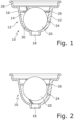
- the Figure 1 shows an odor trap 10 with a closure body 12 which has an interior 14.
- the interior 14 is limited by a wall 16.
- a drain opening 18 is provided in the lower region of the closure body 12.
- the drain opening 18 is closed by a floating body 20, which is spherical in the exemplary embodiment.
- the floating body 20 rests on a web-like guide 22, which has a ventilation opening 24, which is also closed by the floating body 20 in the position shown.
- the web-like guide 22 is essentially vertically aligned. The height relative to the wall 16 decreases towards the drain opening 18.
- a floating body safety device 26 is designed like a ring and is locked on the guide 22.
- the floating body safety device 26 allows a vertical movement of the floating body 20 in a certain area, but prevents the floating body 20 from leaving the odor trap 10.
- the odor trap 10 has a step-shaped edge 28 with which it can be inserted into an opening of a container that can be closed with a lid.
- the odor trap 10 can be fixed in the opening of the container, for example by a nut.
- the floating body 20 In the in the Figure 1 In the closed position shown, the floating body 20 simultaneously closes both the drain opening 18 and the ventilation opening 24. If liquid now enters from above, it reaches the area 30 between the floating body 20 and the wall 16. This causes the floating body 20 to float and move moved vertically upwards. This releases the drain opening 18 and also the ventilation opening 24, as shown in the Figure 2 you can see. Here it can be seen that further upward movement of the floating body 20 is prevented by the floating body safety device 26.
- the floating body safety device 26 is designed in a ring shape, in particular as a slotted ring.
- the slotted ring has tool attacks 32, 34 on both sides of the slot, so that the elastic ring can be compressed in the area of the slot for assembly and disassembly.
- 22 guides 36, 38 are provided in addition to the guide.
- the guides 22, 36, 38 are arranged evenly distributed along the inner circumference of the wall 16.
- the guides 36, 38 can also have a ventilation opening 24.
- the floating body 20 is moved away from the guides 22, 36, 38 Inside of the wall 16 is kept spaced apart so that, on the one hand, liquid can run down between the floating body 20 and the wall 16 and, on the other hand, the floating body 20 is prevented from sticking to the wall 16.
- the floating body 20 is guided in such a way that it can, at least initially, only move vertically to open the drain opening 18 and, in particular, cannot carry out any movement in the radial direction in the closed position.
- Both the floating body 20, the floating body safety device 26, and the closure body 12 can be made from an easy-to-dispose, chemical-resistant plastic.
- they can be made from polypropylene.
- Such plastic is resistant to common cleaners and disinfectants. This eliminates the risk of damage caused by the use of cleaning agents and disinfectants.
- the closure body 12 and the floating body safety device 26 can each be produced using a single injection mold.
- the floating body 20 Since the floating body 20 has a low specific weight and only a small volume remains between the wall 16 and the floating body 20, even small amounts of liquid, in particular introduced urine, generate relatively high buoyancy forces. However, since the floating body 20 only has a small contact surface on the guides 22, 36, 38, sticking can be ruled out even after a long period of non-use. Furthermore, the surface properties of plastic such as polypropylene with their low adhesion forces support the detachment of the floating body 20 from the guides 22, 36, 38.
- the Figure 4 shows a schematic representation of a separation toilet 100.
- the separation toilet 100 comprises a urine collection container 102, which has an odor trap 10 according to the invention at its filling opening 104.
- a urine collecting bowl 106 opens into the odor trap.
- the separation toilet has a faeces collection container 108 to which feces is fed.
- the faeces collection container has an agitator 110, which is rotatably mounted on the faeces collection container 108.
- the faeces collection container 108 can be used together with the agitator 110, i.e. H. can be removed for emptying without the agitator 110 having to be detached or dismantled from the collecting container.
Landscapes
- Engineering & Computer Science (AREA)
- Health & Medical Sciences (AREA)
- Public Health (AREA)
- Life Sciences & Earth Sciences (AREA)
- Hydrology & Water Resources (AREA)
- Water Supply & Treatment (AREA)
- Aviation & Aerospace Engineering (AREA)
- Environmental & Geological Engineering (AREA)
- Sanitary Device For Flush Toilet (AREA)
- Sink And Installation For Waste Water (AREA)
Applications Claiming Priority (1)
| Application Number | Priority Date | Filing Date | Title |
|---|---|---|---|
| DE102022122529.1A DE102022122529A1 (de) | 2022-09-06 | 2022-09-06 | Geruchsverschluss und Trenntoilette mit Geruchsverschluss |
Publications (3)
| Publication Number | Publication Date |
|---|---|
| EP4335984A1 true EP4335984A1 (fr) | 2024-03-13 |
| EP4335984C0 EP4335984C0 (fr) | 2025-10-15 |
| EP4335984B1 EP4335984B1 (fr) | 2025-10-15 |
Family
ID=87760593
Family Applications (1)
| Application Number | Title | Priority Date | Filing Date |
|---|---|---|---|
| EP23191879.8A Active EP4335984B1 (fr) | 2022-09-06 | 2023-08-17 | Siphon et toilettes de séparation dotées d'un siphon |
Country Status (3)
| Country | Link |
|---|---|
| EP (1) | EP4335984B1 (fr) |
| DE (1) | DE102022122529A1 (fr) |
| ES (1) | ES3052492T3 (fr) |
Citations (5)
| Publication number | Priority date | Publication date | Assignee | Title |
|---|---|---|---|---|
| CH685171A5 (de) | 1992-02-28 | 1995-04-13 | Semadeni Ag | Ventileinrichtung. |
| EP3241749A1 (fr) * | 2016-05-04 | 2017-11-08 | Airbus Operations GmbH | Système et procédé d'élimination de fluide à partir d'un évier |
| US20190136495A1 (en) * | 2017-11-06 | 2019-05-09 | Helvex, S.A. De C.V | Way out valve for urinals with double little ball |
| DE202019005509U1 (de) * | 2019-10-25 | 2020-10-29 | Sascha Gerner | Trenntoilette, Trenntoiletten-System und Verwendungen |
| DE102019128862A1 (de) | 2019-10-25 | 2021-04-29 | Sascha Gerner | Trenntoilette, Trenntoiletten-System und Verwendungen |
Family Cites Families (2)
| Publication number | Priority date | Publication date | Assignee | Title |
|---|---|---|---|---|
| DE102007034998B4 (de) | 2007-07-26 | 2009-11-26 | Aoa Apparatebau Gauting Gmbh | Vakuumentsorgungsanlage für Flüssigkeiten, insbesondere an Bord eines Fahrzeuges |
| DE102007052076B3 (de) | 2007-10-31 | 2009-01-02 | BSH Bosch und Siemens Hausgeräte GmbH | Wasserführendes Haushaltsgerät mit Einspülschale für Flüssigkeiten |
-
2022
- 2022-09-06 DE DE102022122529.1A patent/DE102022122529A1/de active Pending
-
2023
- 2023-08-17 EP EP23191879.8A patent/EP4335984B1/fr active Active
- 2023-08-17 ES ES23191879T patent/ES3052492T3/es active Active
Patent Citations (5)
| Publication number | Priority date | Publication date | Assignee | Title |
|---|---|---|---|---|
| CH685171A5 (de) | 1992-02-28 | 1995-04-13 | Semadeni Ag | Ventileinrichtung. |
| EP3241749A1 (fr) * | 2016-05-04 | 2017-11-08 | Airbus Operations GmbH | Système et procédé d'élimination de fluide à partir d'un évier |
| US20190136495A1 (en) * | 2017-11-06 | 2019-05-09 | Helvex, S.A. De C.V | Way out valve for urinals with double little ball |
| DE202019005509U1 (de) * | 2019-10-25 | 2020-10-29 | Sascha Gerner | Trenntoilette, Trenntoiletten-System und Verwendungen |
| DE102019128862A1 (de) | 2019-10-25 | 2021-04-29 | Sascha Gerner | Trenntoilette, Trenntoiletten-System und Verwendungen |
Also Published As
| Publication number | Publication date |
|---|---|
| EP4335984C0 (fr) | 2025-10-15 |
| DE102022122529A1 (de) | 2024-03-07 |
| ES3052492T3 (en) | 2026-01-07 |
| EP4335984B1 (fr) | 2025-10-15 |
Similar Documents
| Publication | Publication Date | Title |
|---|---|---|
| DE8716353U1 (de) | Vorrichtung zur Reinigung verstopfter Abwasserrohre mittels eines Wasser- und Luftwirbels | |
| DE3534932A1 (de) | Vorrichtung zum abscheiden von fluessigkeiten, z.b. kondensat, aus druckgas wie druckluft | |
| DE2701157A1 (de) | Geruchsverschluss fuer fluessigkeiten | |
| EP4335984A1 (fr) | Siphon et toilettes de séparation dotées d'un siphon | |
| EP1548193B1 (fr) | Dispositif pour empêcher l'eau d'entrer dans un puit de regard | |
| DE10246866A1 (de) | Speicherbehälter, insbesondere Toilettenspülkasten | |
| DE3127487A1 (de) | Reinigungsrohr | |
| DE3822555C2 (fr) | ||
| WO2017194463A1 (fr) | Vanne de vidange pour réservoir de chasse-d'eau et réservoir de chasse-d'eau muni d'une vanne de vidange | |
| DE4035225C2 (de) | Kondensatsammelbehälter für einen Wäschetrockner | |
| DE4291643C2 (de) | Vorrichtung zum Verhindern des Eindringens von Tieren, insbesondere Ratten, in ein Rohrnetzwerk | |
| EP3805473B1 (fr) | Piège à odeurs et système d'écoulement | |
| DE2849207A1 (de) | Spuelgeraet fuer wc-becken | |
| CH675007A5 (fr) | ||
| EP3889517A1 (fr) | Dispositif de renvoi de condensat | |
| DE2740048A1 (de) | Abschliessbarer behaelter | |
| DE3636328A1 (de) | Vorrichtung zum einbau in das abflusssystem von badewannen und dgl. mit whirlpool-einrichtung | |
| EP0058823A1 (fr) | Réservoir de chasse d'eau | |
| EP0144994A2 (fr) | Piège avec une substance attractive contre insectes volants sylvicoles, en particulier bostryche | |
| DE4425244C1 (de) | Ventil zur Ent- und Belüftung insbesondere einer Abwasserleitung | |
| DE19748019A1 (de) | Bodenablauf | |
| DE69105268T2 (de) | Druckknopfspülmechanismus mit eintauchbarem Körper. | |
| DE725966C (de) | Be- und Entlueftungseinrichtung fuer Wasserleitungen | |
| DE29507730U1 (de) | Infusionsgerät | |
| DE29909423U1 (de) | Tropfgeschützter auslaufsicherer Trinkbecher |
Legal Events
| Date | Code | Title | Description |
|---|---|---|---|
| PUAI | Public reference made under article 153(3) epc to a published international application that has entered the european phase |
Free format text: ORIGINAL CODE: 0009012 |
|
| STAA | Information on the status of an ep patent application or granted ep patent |
Free format text: STATUS: THE APPLICATION HAS BEEN PUBLISHED |
|
| AK | Designated contracting states |
Kind code of ref document: A1 Designated state(s): AL AT BE BG CH CY CZ DE DK EE ES FI FR GB GR HR HU IE IS IT LI LT LU LV MC ME MK MT NL NO PL PT RO RS SE SI SK SM TR |
|
| STAA | Information on the status of an ep patent application or granted ep patent |
Free format text: STATUS: REQUEST FOR EXAMINATION WAS MADE |
|
| 17P | Request for examination filed |
Effective date: 20240409 |
|
| RBV | Designated contracting states (corrected) |
Designated state(s): AL AT BE BG CH CY CZ DE DK EE ES FI FR GB GR HR HU IE IS IT LI LT LU LV MC ME MK MT NL NO PL PT RO RS SE SI SK SM TR |
|
| GRAP | Despatch of communication of intention to grant a patent |
Free format text: ORIGINAL CODE: EPIDOSNIGR1 |
|
| STAA | Information on the status of an ep patent application or granted ep patent |
Free format text: STATUS: GRANT OF PATENT IS INTENDED |
|
| INTG | Intention to grant announced |
Effective date: 20250717 |
|
| GRAS | Grant fee paid |
Free format text: ORIGINAL CODE: EPIDOSNIGR3 |
|
| GRAA | (expected) grant |
Free format text: ORIGINAL CODE: 0009210 |
|
| STAA | Information on the status of an ep patent application or granted ep patent |
Free format text: STATUS: THE PATENT HAS BEEN GRANTED |
|
| AK | Designated contracting states |
Kind code of ref document: B1 Designated state(s): AL AT BE BG CH CY CZ DE DK EE ES FI FR GB GR HR HU IE IS IT LI LT LU LV MC ME MK MT NL NO PL PT RO RS SE SI SK SM TR |
|
| REG | Reference to a national code |
Ref country code: GB Ref legal event code: FG4D Free format text: NOT ENGLISH Ref country code: CH Ref legal event code: F10 Free format text: ST27 STATUS EVENT CODE: U-0-0-F10-F00 (AS PROVIDED BY THE NATIONAL OFFICE) Effective date: 20251015 |
|
| REG | Reference to a national code |
Ref country code: CH Ref legal event code: W10 Free format text: ST27 STATUS EVENT CODE: U-0-0-W10-W00 (AS PROVIDED BY THE NATIONAL OFFICE) Effective date: 20251022 Ref country code: CH Ref legal event code: Y10 Free format text: ST27 STATUS EVENT CODE: U-0-0-Y10-Y00 (AS PROVIDED BY THE NATIONAL OFFICE) Effective date: 20251022 |
|
| REG | Reference to a national code |
Ref country code: IE Ref legal event code: FG4D Free format text: LANGUAGE OF EP DOCUMENT: GERMAN |
|
| REG | Reference to a national code |
Ref country code: DE Ref legal event code: R096 Ref document number: 502023001997 Country of ref document: DE |
|
| REG | Reference to a national code |
Ref country code: CH Ref legal event code: R17 Free format text: ST27 STATUS EVENT CODE: U-0-0-R10-R17 (AS PROVIDED BY THE NATIONAL OFFICE) Effective date: 20251117 |
|
| RAP4 | Party data changed (patent owner data changed or rights of a patent transferred) |
Owner name: GERNER, SASCHA ALEXANDER |
|
| RIN2 | Information on inventor provided after grant (corrected) |
Inventor name: GERNER, SASCHA ALEXANDER |
|
| U01 | Request for unitary effect filed |
Effective date: 20251028 |
|
| U07 | Unitary effect registered |
Designated state(s): AT BE BG DE DK EE FI FR IT LT LU LV MT NL PT RO SE SI Effective date: 20251103 |
|
| REG | Reference to a national code |
Ref country code: ES Ref legal event code: FG2A Ref document number: 3052492 Country of ref document: ES Kind code of ref document: T3 Effective date: 20260107 |
|
| PG25 | Lapsed in a contracting state [announced via postgrant information from national office to epo] |
Ref country code: NO Free format text: LAPSE BECAUSE OF FAILURE TO SUBMIT A TRANSLATION OF THE DESCRIPTION OR TO PAY THE FEE WITHIN THE PRESCRIBED TIME-LIMIT Effective date: 20260115 |
|
| PG25 | Lapsed in a contracting state [announced via postgrant information from national office to epo] |
Ref country code: HR Free format text: LAPSE BECAUSE OF FAILURE TO SUBMIT A TRANSLATION OF THE DESCRIPTION OR TO PAY THE FEE WITHIN THE PRESCRIBED TIME-LIMIT Effective date: 20251015 |
|
| PG25 | Lapsed in a contracting state [announced via postgrant information from national office to epo] |
Ref country code: RS Free format text: LAPSE BECAUSE OF FAILURE TO SUBMIT A TRANSLATION OF THE DESCRIPTION OR TO PAY THE FEE WITHIN THE PRESCRIBED TIME-LIMIT Effective date: 20260115 |
|
| PG25 | Lapsed in a contracting state [announced via postgrant information from national office to epo] |
Ref country code: IS Free format text: LAPSE BECAUSE OF FAILURE TO SUBMIT A TRANSLATION OF THE DESCRIPTION OR TO PAY THE FEE WITHIN THE PRESCRIBED TIME-LIMIT Effective date: 20260215 |
|
| PG25 | Lapsed in a contracting state [announced via postgrant information from national office to epo] |
Ref country code: PL Free format text: LAPSE BECAUSE OF FAILURE TO SUBMIT A TRANSLATION OF THE DESCRIPTION OR TO PAY THE FEE WITHIN THE PRESCRIBED TIME-LIMIT Effective date: 20251015 |