EP4335997B1 - Module de fermeture pour une porte et porte dotée d'un module de fermeture - Google Patents
Module de fermeture pour une porte et porte dotée d'un module de fermeture Download PDFInfo
- Publication number
- EP4335997B1 EP4335997B1 EP23188044.4A EP23188044A EP4335997B1 EP 4335997 B1 EP4335997 B1 EP 4335997B1 EP 23188044 A EP23188044 A EP 23188044A EP 4335997 B1 EP4335997 B1 EP 4335997B1
- Authority
- EP
- European Patent Office
- Prior art keywords
- locking
- base
- door
- section
- anchor section
- Prior art date
- Legal status (The legal status is an assumption and is not a legal conclusion. Google has not performed a legal analysis and makes no representation as to the accuracy of the status listed.)
- Active
Links
Images






Classifications
-
- E—FIXED CONSTRUCTIONS
- E05—LOCKS; KEYS; WINDOW OR DOOR FITTINGS; SAFES
- E05B—LOCKS; ACCESSORIES THEREFOR; HANDCUFFS
- E05B65/00—Locks or fastenings for special use
- E05B65/0042—For refrigerators or cold rooms
-
- E—FIXED CONSTRUCTIONS
- E05—LOCKS; KEYS; WINDOW OR DOOR FITTINGS; SAFES
- E05B—LOCKS; ACCESSORIES THEREFOR; HANDCUFFS
- E05B1/00—Knobs or handles for wings; Knobs, handles, or press buttons for locks or latches on wings
- E05B1/003—Handles pivoted about an axis perpendicular to the wing
-
- E—FIXED CONSTRUCTIONS
- E05—LOCKS; KEYS; WINDOW OR DOOR FITTINGS; SAFES
- E05B—LOCKS; ACCESSORIES THEREFOR; HANDCUFFS
- E05B1/00—Knobs or handles for wings; Knobs, handles, or press buttons for locks or latches on wings
- E05B1/0053—Handles or handle attachments facilitating operation, e.g. by children or burdened persons
-
- E—FIXED CONSTRUCTIONS
- E05—LOCKS; KEYS; WINDOW OR DOOR FITTINGS; SAFES
- E05B—LOCKS; ACCESSORIES THEREFOR; HANDCUFFS
- E05B63/00—Locks or fastenings with special structural characteristics
- E05B63/0056—Locks with adjustable or exchangeable lock parts
-
- E—FIXED CONSTRUCTIONS
- E05—LOCKS; KEYS; WINDOW OR DOOR FITTINGS; SAFES
- E05B—LOCKS; ACCESSORIES THEREFOR; HANDCUFFS
- E05B63/00—Locks or fastenings with special structural characteristics
- E05B63/06—Locks or fastenings with special structural characteristics with lengthwise-adjustable bolts ; with adjustable backset, i.e. distance from door edge
-
- E—FIXED CONSTRUCTIONS
- E05—LOCKS; KEYS; WINDOW OR DOOR FITTINGS; SAFES
- E05C—BOLTS OR FASTENING DEVICES FOR WINGS, SPECIALLY FOR DOORS OR WINDOWS
- E05C3/00—Fastening devices with bolts moving pivotally or rotatively
- E05C3/02—Fastening devices with bolts moving pivotally or rotatively without latching action
- E05C3/04—Fastening devices with bolts moving pivotally or rotatively without latching action with operating handle or equivalent member rigid with the bolt
- E05C3/041—Fastening devices with bolts moving pivotally or rotatively without latching action with operating handle or equivalent member rigid with the bolt rotating about an axis perpendicular to the surface on which the fastener is mounted
- E05C3/043—Fastening devices with bolts moving pivotally or rotatively without latching action with operating handle or equivalent member rigid with the bolt rotating about an axis perpendicular to the surface on which the fastener is mounted the pivot being between bolt and handle
-
- E—FIXED CONSTRUCTIONS
- E05—LOCKS; KEYS; WINDOW OR DOOR FITTINGS; SAFES
- E05B—LOCKS; ACCESSORIES THEREFOR; HANDCUFFS
- E05B3/00—Fastening knobs or handles to lock or latch parts
Definitions
- the invention relates to a locking assembly of a door of a cold storage room according to the preamble of claim 1 or 2.
- the first type of locking assembly has a pull handle on the outside and a push handle on the inside.
- the second type of locking assembly is commonly referred to as a rotary-press lock.
- a rotating handle bar on both the inside and outside of the door, with both handle bars being connected to one another via a bolt that passes through the door leaf.
- a locking bolt is coupled to the rotary handle on the inside. In a closed position, this engages behind a strike plate and is moved into an open position by turning the door handle and the axis of rotation defined by the connecting bolt.
- EP 0 374 351 A1 A box lock for a sliding door is known, which reveals a bolt that swings out from the box lock.
- the depth of engagement of the swivel bolt in the strike plate on the door frame side can be adjusted via a sliding seat of the bolt on a pin.
- a locking set is disclosed in which the actuating handle is designed to pivot about an axis parallel to the door leaf.
- the locking element is directly coupled to the actuating handle and its position can be adjusted via a thread.
- Temperature control rooms are usually assembled from prefabricated components at the place of use.
- the components usually consist of a metal support frame filled with insulating foam.
- the wall elements are often provided with tongue and groove structures on their joining surfaces, which interlock with one another. This makes the construction much easier.
- the doors for temperature control rooms are inserted into appropriately prepared wall elements on site.
- the fittings of the doors, including the locking assembly, are fitted on site to the respective Attached to the door panel in a way that is adapted to the installation situation. To do this, the assembly staff drills the appropriate holes and cutouts in the door panel and the associated wall elements on site. After dismantling the door, it is adjusted in the door frame and in relation to the existing seals.
- the door is moved along the X, Y and Z axes of a geometric coordinate system by manipulating the door hinges in particular.
- certain limits are placed on the horizontal adjustment path along the X axis in particular due to the engagement of the locking element in the strike plate.
- the object of the invention is to improve the adjustability of the door of a refrigerating room and in particular to enable a larger horizontal adjustment range.
- the locking component can be pushed into the base and fixed in this new installation position. In this way, the horizontal movement of the door during adjustment work is compensated for by a corresponding counter movement of the locking component in the base.
- a form-locking fastening has the significant advantage that an unintentional change in the position of the locking component, for example due to collision with objects when entering or leaving the temperature control room, is reliably avoided.
- the radially outer end of the locking portion is provided with a spring-loaded latch, wherein the latch in particular forms the locking portion.
- the invention therefore provides for the use of a locking element whose mounting position can be changed or adjusted both in locking assemblies with a pull handle and in locking assemblies in the form of a twist-press lock.
- the first base 11 carries a first handle part 13, also referred to as an external handle, and spaced this from a door leaf (not shown).
- the first handle part 13 is fixed in the area of the front side of the first base 11 facing away from the rear.
- the first handle part 13 is detachably arranged on the first base 11.
- the first base 11 has a radially directed mandrel 14, which is received by a mandrel holder 15 of the first handle part 13 that has a complementary shape.
- Fastening means 16 in the form of screws, serve to fasten the first handle part 13 to the mandrel 14 of the first base 11.
- the complementary shape of the mandrel 14 in the mandrel holder 15 ensures a safe torque transmission from the first handle part 13 to the first base 11.
- the first pin 14 has a first support bolt 17.
- This support bolt 17 originates from the first pin 14 axially in the direction of the rear side 12 of the first base 11 and is supported on the outer circumference of the first base 11. Pressure forces applied to the first handle part 13 in the direction of the door leaf (not shown) or in the direction of the plane spanned by the rear side 12 of the first base 11 are absorbed by the first support bolt 17 and safely transferred to the first base 11. This ensures that the door (not shown) can be closed by exerting pressure on the first handle part 13 without damage.
- the second base 41 is arranged with its rear side 42 rotatably mounted on a door leaf (not shown) about the geometric axis of rotation D.
- the second base 41 will also be referred to later as the inner base 41.
- a second handle part 43, the inner handle, is attached to the second base 41.
- a second pin 44 also emerges from the second inner base 41, which sits in a second pin receptacle 45 of the second handle part 43 and is fixed to the second handle part 43 via fastening means 46 in the form of screws.
- the second pin 44 also forms an axially directed second support bolt 47, which corresponds in design and function to the first support bolt 17.
- the first embodiment of the invention has a plastic base 11/41 and a plastic handle part 13/43. If other materials are used, for example at least one base made of metal, the support bar 17/47 can be dispensed with if the stability is sufficient.
- the door leaf (not shown) is penetrated by a drive pin, which ensures the physical Actuating axis B in the form of a rotation axis of the bases 11 and 41 and couples the bases 11 and 41 together in a rotationally fixed manner.
- the second base 41 is provided with a radially accessible channel 51 or blind hole 51 in which a locking component R in the form of a locking bolt 52 is accommodated. This special design of the second base 41 will be discussed in more detail later.
- FIGS. 3 and 4 show a representation of the base 11/41 and the handle part 13/43 assembled together.
- the mandrel holder 15/45 of the handle part 13/43 receives the mandrel 14/44 in a form-fitting manner, so that a closed, rear surface of the handle part 13/43 is formed.
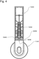
- the front view of the unit consisting of base 11/41 and handle part 13/43 Figure 4 shows the internal structure of the handle part 13/43.
- the handle part 13/43 is not solid, but rather a hollow body that is provided with various stiffening webs to dissipate the force. These form nodes axially in front of the mandrel 14/44, through which the fastening means 16/46 (not shown here) are passed in order to fasten the handle part 13/43 to the mandrel 14/44.
- An elastomer element 20/50 is arranged in a gap between the handle part 13/43 and the base 11/41 between the support surfaces 18/48 and 19/49, which absorbs the tilting moments of the handle part 13/43 when a door (not shown) is opened and transfers them to the base 11/41.
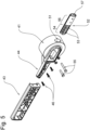
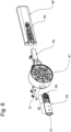
- FIGS. 5 and 6 show an exploded view of the inner base 41 and the inner handle 43 in view of their front side ( Figure 5 or back Figure 6 ).
- the locking bolt 52 has two elongated holes 53 arranged one behind the other in the radial direction, which are arranged in its anchor section 54. These anchor sections 54 are intended to be immersed in the channel 51.
- the anchor section 54 is fixed there by two fastening bolts 55.
- the anchor section 54 can be fixed in different mounting positions with regard to its radial immersion depth, whereby the elongated holes 53 define the maximum immersion depth or the maximum extension position of the anchor section 54 in the channel 51 via their unspecified end stops.
- the radial displacement of the anchor section 54 within the channel 51 allows the radial projection of the locking section 56 of the locking bolt 52 to be defined. In this way, it can be ensured that the locking section 56 securely engages behind the strike plate (not shown) in a locking manner, regardless of the material and assembly tolerances.
- the locking bolt 52 can be provided with a spring-loaded latch at its free end facing away from the inner base 41 in order to ensure that it remains in the closed position when
- the locking bolt shown here in Figures 1 and 2 as well as 5 and 6 has a latch receiving space 57 at its free end, which is closed by a plug 58 (see Figures 1 and 2 ) is closed if a latch is not used. If, however, a latch is to be arranged on the locking bolt 52, this can be inserted into the latch receiving space 57 instead of the closure plug, so that one and the same locking bolt 52 can be used both with and without a latch. Alternatively, a locking bolt 52 without a latch can be exchanged for a locking bolt 52 with a latch.
- the locking bolt 52 has a positive locking contour 59 in the area of its anchor section 54, which has several positive locking elements of ribs aligned parallel to one another.
- Within the channel 51 there is a counter contour into which the positive locking contour 59 of the locking bolt 52 engages in order to create a positive connection when fastening the locking bolt 52 in the selected installation position in the channel 51 and to prevent the locking bolt 52 from being accidentally pushed into the channel 51.
- the selected installation position of the locking bolt 52 in particular the radial projection of the locking section 56, is secured with regard to the strike plate after the adjustment has been made and the locking function is guaranteed.
- the locking assembly 10 is used to be arranged on a cold storage door.
- the cold storage door can be locked and unlocked as well as opened and closed using the locking assembly 10.
- the outer base 11 is fixed to the outside of the door and the inner base 41 to the inside of the door. Both bases 11/41 are connected to one another in a rotational manner by a drive pin, so that a Rotational movement of the outer base 11 results in a rotational movement of the inner base 41 and vice versa. In this way, the locking bolt 52 can be moved from the outside between its open position and its closed position.
- the invention shows in a highly advantageous manner first of all the possibility of being able to provide a base 11/41 with different handle parts 13/43 both with regard to the technical requirements and with regard to individual design requirements, in that the handle parts 13/43 are detachably arranged on the base 11/41.
- the invention shows how the locking component R in the form of a locking bolt 52 of the inner base 41 can be fixed in a variable position in order to compensate for manufacturing and assembly tolerances relative to the strike plate.
- the locking bolt 52 can optionally be used to enable a latch-based and latch-free closure. It is of course also conceivable that different locking bolts 52 can be accommodated by the inner base 41.
- the first embodiment of the invention discloses a modular locking assembly 10 adapted to individual needs and individual assembly and operating situations.
- FIGS. 7 to 13 show a second embodiment of the invention.
- the locking assembly as a whole is provided with the reference 110.
- the locking assembly 110 of the second embodiment also comprises a first base 111, which is also referred to as an outer base.
- the outer base 111 comprises a handle part 113, which is also referred to as an outer handle 113 and represents an actuating device within the meaning of the claim.
- Part of the locking assembly 110 of the second embodiment is also a second base 141, which is also referred to as an inner base 141 and which carries a second actuating handle in the form of a push handle 143.
- the push handle 143 is also an actuating handle in the sense of the claim.
- the outside handle 112 is connected to the push handle 143 by an actuating axis B.
- the first base 111 is arranged on the outside of a door (not shown), whereas the second base 141 is arranged on the inside of the door.
- the actuating axis B passes through the door leaf to connect the outside handle 112 to the push handle 143.
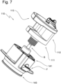
- the second base carries a locking component 152, the locking section 156 of which is designed as a locking latch F.
- the locking component 152 In Figure 7 Only the latch F is visible from the locking component 152.
- the outer handle 112 In order to remove the latch F from its Figure 7 In order to move the locking latch F from the locking position shown, which projects radially relative to the base 141, into an open position, the outer handle 112 is pulled axially with respect to the actuating axis B. This induces a corresponding axial movement of the actuating axis B, which moves the locking latch F into the second base 141 and thus brings it into its open position.
- the one base 141 has two handle wings 170. Using these handle wings 170, the door can also be opened from the inside via the locking assembly 110 according to the invention can be pivoted open or closed.
- Figure 8 It can be seen that the push handle 143 is arranged axially displaceably in the inner base 141.
- Figure 9 shows the inner base 141 in an exploded view. From this it can be seen that the actuation axis B passes through the inner base 141 and reaches into the push handle 143. In the exemplary embodiment it is secured there by a hexagon nut 171.
- the push handle 143 itself consists of a handle body 172 and a handle cover 173, which is secured to the handle body 172 by screws shown but not further designated.
- the handle body 172 arranged in the inner base 141 is held in its axial outer position by a handle body spring 174. If, as described above, the push handle 143 is moved axially into the inner base 141 in order to move the locking component 152 into its open position, the handle body spring 174 ensures a counter movement to its starting position after the push handle 143 is actuated.
- the locking component 152 consists first of the already mentioned locking latch F. This forms a seat 175 for a latch spring element 176.
- the locking latch F serves as the locking section 156 in the locking assembly 110.
- Part of the locking component 152 is also an anchor section 154, which is equipped at its end facing the latch F with two guide webs 177 which are parallel to one another and spaced apart from one another and which accommodate the latch F between them.
- a roller element 178 mounted in the anchor section 154 reduces the friction between the anchor section 154 of the locking component 152 and the push-out lug 179 of the push handle 143.
- Part of the locking component 152 is then an abutment 180, which is a threaded section for the retaining screw 181 and helps to hold the latch F in a selected mounting position.
- Figure 12 shows a top view of the latch bolt F.
- the latch bolt F is provided with an approximately U-shaped cutout 182.
- a holding plate 183 is arranged below the cutout 182, the surface of which facing the viewer is provided with a form-fitting contour 159. In the present embodiment, these are applied form-fitting webs 184.
- the holding plate 183 is penetrated by a through hole 185, which ensures the passage of the holding screw 181.
- Figure 13 shows a view from below of the anchor section 154.
- the anchor section 154 At its end facing away from the latch F, the anchor section 154 has a bearing eye 186 for the roller element 178.
- the anchor section 154 is also equipped with a retaining tongue 187 which extends between the guide webs 177 in the direction of the latch F.
- the surface of the retaining tongue 187 facing the viewer is also provided with a positive locking contour 159 which corresponds to the positive locking contour 159 of the latch F.
- Positive locking webs 184 have also been selected here.
- the retaining tongue 187 is penetrated by an elongated hole 188 whose longitudinal extent is directed radially with respect to the actuating axis B or parallel to the path of movement of the latch F. When assembled, the elongated hole 188 is aligned with the through hole 185 of the latch bolt F.
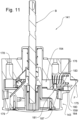
- Figure 11 shows a sectional view according to section line AA in Figure 10 .
- the cut is therefore along the path of movement of the latch F or along the longitudinal extension of the latch component R.
- Figure 11 one can first see that the ejection nose 179 of the push handle 143 dips into the anchor section 154 of the locking component R and slides there on the roller element 178. An axial movement of the push handle 143 in the inner base 141 thus leads to a retraction of the locking component R from its normal position into an open position.
- the latch spring element 176 is supported on the seat 175 of the latch bolt F on the one hand and on an unspecified wall section of the inner base 141 on the other.
- the latch spring element 176 is put under tension and moves the latch bolt F back into the normal position after reaching the open position.
- the retaining tongue 187 of the anchor section 154 rests on the retaining plate 183 of the latch F, with the form-fitting contours 159 of both elements facing each other and engaging with each other.
- the abutment 180 supports the retaining plate 183 and provides a thread for the retaining screw 181.
- the elongated hole 188 of the retaining tongue 187, the through hole 185 of the latch F and the thread of the abutment 180 are aligned in the assembled state.
- the retaining screw 181 presses the retaining tongue 187 and the retaining plate 183 with their form-fitting contours onto each other, so that when the retaining screw 181 is tightened, a relative movement of the latch F and the anchor section 154 of the latch component R is reliably prevented.
- the latch bolt F can be moved radially relative to the anchor section 154 with respect to the actuation axis B, i.e. can be pulled out of the inner base 141 or pushed into it. In this way, the latch bolt F can be adjusted relative to the strike plate (not shown) for optimal engagement.
Landscapes
- Engineering & Computer Science (AREA)
- Structural Engineering (AREA)
- Mechanical Engineering (AREA)
- Physics & Mathematics (AREA)
- Thermal Sciences (AREA)
- Lock And Its Accessories (AREA)
- Refrigerator Housings (AREA)
Claims (7)
- Module de fermeture (10, 110) d'une porte de chambre froide,- avec une poignée d'actionnement,- avec un élément de verrouillage (52, 152) qui présente une section d'ancrage (54, 154) et une section de verrouillage (56, 156),- avec un axe d'actionnement (B) qui relie l'élément de verrouillage (52, 152) à la poignée d'actionnement,- avec un socle (41, 141) dans lequel l'élément de verrouillage (52, 152) est monté avec sa section d'ancrage (54, 154) et par rapport auquel la section de verrouillage (56, 156) fait saillie radialement par rapport à l'axe d'actionnement (B),- avec une plaque de fermeture derrière laquelle la section de verrouillage (56, 156) de l'élément de verrouillage (52, 152) vient en prise dans une position de verrouillage,- l'élément de verrouillage (52, 152) pouvant passer, à l'aide de la poignée d'actionnement par l'intermédiaire de l'axe d'actionnement (B), de sa position de verrouillage en prise arrière sur la plaque de fermeture à une position d'ouverture sans prise sur la plaque de fermeture,- l'axe d'actionnement (B) accouplant l'un avec l'autre la poignée d'actionnement et l'élément de verrouillage (152) en faisant office de tige de traction et un mouvement de traction de l'axe d'actionnement (B) sensiblement linéaire par rapport à l'axe d'actionnement (B), induit par la poignée d'actionnement, plaçant l'élément de verrouillage (152) dans sa position d'ouverture,caractérisé en ce que- la section d'ancrage (54, 154) de l'élément de verrouillage (52, 152) peut adopter différentes positions de montage dans le socle (41, 141), en particulier est montée dans le socle (41, 141) de façon mobile radialement par rapport à l'axe d'actionnement (B),- la saillie radiale de la section de verrouillage (56, 156) par rapport au socle (41, 141) variant en fonction de la position de montage de la section d'ancrage (54, 154).
- Module de fermeture (10, 110) d'une porte de chambre froide,- avec une poignée d'actionnement,- avec un élément de verrouillage (52, 152) qui présente une section d'ancrage (54, 154) et une section de verrouillage (56, 156),- avec un axe d'actionnement (B) qui relie l'élément de verrouillage (52, 152) à la poignée d'actionnement,- avec un socle (41, 141) dans lequel l'élément de verrouillage (52, 152) est monté avec sa section d'ancrage (54, 154) et par rapport auquel la section de verrouillage (56, 156) fait saillie radialement par rapport à l'axe d'actionnement (B),- avec une plaque de fermeture derrière laquelle la section de verrouillage (56, 156) de l'élément de verrouillage (52, 152) vient en prise dans une position de verrouillage,- l'élément de verrouillage (52, 152) pouvant passer, à l'aide de la poignée d'actionnement par l'intermédiaire de l'axe d'actionnement (B), de sa position de verrouillage en prise arrière sur la plaque de fermeture à une position d'ouverture sans prise sur la plaque de fermeture,- l'axe d'actionnement (B) étant un axe de rotation (D) autour duquel la poignée d'actionnement montée sur une porte de chambre froide peut pivoter,- le socle (41) faisant saillie radialement par rapport au panneau de porte et une partie de poignée (43) espacée axialement du panneau de porte sortant radialement de celui-ci, le module de fermeture (10) étant soumis à un couple de rotation pour verrouiller et déverrouiller la porte et des forces de traction et de pression agissant sur la partie de poignée (43) pour faire pivoter la porte dans le sens de l'ouverture ou de la fermeture,- l'élément de verrouillage (52) étant un boulon de verrouillage et- l'axe d'actionnement (B) étant couplé de façon solidaire en rotation avec le socle (41), caractérisé en ce que- la section d'ancrage (54, 154) de l'élément de verrouillage (52, 152) peut adopter différentes positions de montage dans le socle (41, 141), en particulier est montée dans le socle (41, 141) de façon mobile radialement par rapport à l'axe d'actionnement (B),- la saillie radiale de la section de verrouillage (56, 156) par rapport au socle (41, 141) variant en fonction de la position de montage de la section d'ancrage (54, 154).
- Module de fermeture selon la revendication 1 ou 2, caractérisé en ce que la section d'ancrage (54, 154) et le socle (41, 141) présentent des éléments à ajustement de forme (59, 159) correspondant entre eux qui s'interpénètrent dans la position de montage respective.
- Module de fermeture selon une des revendications 1 à 3, caractérisé en ce qu'il est prévu au moins un, de préférence plusieurs moyens de fixation (55, 181) qui maintiennent la section d'ancrage (54, 154) sur le socle (41, 141), lesquels moyens de fixation (46, 181) peuvent adopter au choix une première position de fixation agençant simplement la section d'ancrage (54, 154) en ce qui concerne la position de montage, mais néanmoins variable, ou une deuxième position de fixation fixant la section d'ancrage (54, 154) dans une position de montage.
- Module de fermeture selon la revendication 4, caractérisé en ce que la section d'ancrage (54, 154) est dotée d'au moins un, de préférence de plusieurs trous oblongs (53, 188) orientés axialement que traverse(nt) au moins un, de préférence plusieurs moyens de fixation (55, 181), en particulier des boulons filetés, pour disposer la section d'ancrage (54, 154) dans le socle (41, 141) et le long desquels la section d'ancrage (54, 154) est montée dans le socle (41, 141) de façon coulissante dans la direction axiale pour adopter différentes positions de montage.
- Module de fermeture selon une des revendications 1 à 5, caractérisé en ce que l'extrémité extérieure radiale de la section de verrouillage (56, 156) est dotée d'un pêne demi-tour chargé par ressort (F), et en particulier que ce pêne demi-tour chargé par ressort (F) constitue la section de verrouillage (56, 156).
- Porte de chambre froide avec un panneau de porte monté dans un châssis de porte d'un réfrigérateur, avec une feuillure de porte et une feuillure de châssis correspondante, dans la feuillure de porte et/ou la feuillure de châssis étant agencé un joint de porte, avec une plaque de fermeture montée sur le châssis de porte, caractérisée en ce qu'un module de fermeture (10, 110) selon une des revendications 1 à 6 est monté sur la porte.
Applications Claiming Priority (1)
| Application Number | Priority Date | Filing Date | Title |
|---|---|---|---|
| EP22195029.8A EP4335996B1 (fr) | 2022-09-12 | 2022-09-12 | Module de fermeture pour une porte et porte dotée d'un module de fermeture |
Publications (2)
| Publication Number | Publication Date |
|---|---|
| EP4335997A1 EP4335997A1 (fr) | 2024-03-13 |
| EP4335997B1 true EP4335997B1 (fr) | 2025-01-29 |
Family
ID=83283184
Family Applications (2)
| Application Number | Title | Priority Date | Filing Date |
|---|---|---|---|
| EP22195029.8A Active EP4335996B1 (fr) | 2022-09-12 | 2022-09-12 | Module de fermeture pour une porte et porte dotée d'un module de fermeture |
| EP23188044.4A Active EP4335997B1 (fr) | 2022-09-12 | 2023-07-27 | Module de fermeture pour une porte et porte dotée d'un module de fermeture |
Family Applications Before (1)
| Application Number | Title | Priority Date | Filing Date |
|---|---|---|---|
| EP22195029.8A Active EP4335996B1 (fr) | 2022-09-12 | 2022-09-12 | Module de fermeture pour une porte et porte dotée d'un module de fermeture |
Country Status (1)
| Country | Link |
|---|---|
| EP (2) | EP4335996B1 (fr) |
Family Cites Families (11)
| Publication number | Priority date | Publication date | Assignee | Title |
|---|---|---|---|---|
| DE1553599A1 (de) * | 1966-09-23 | 1970-03-19 | Schulte Schlagbaum Schlossfab | Drehstangenschloss |
| GB1444555A (en) * | 1972-12-28 | 1976-08-04 | West Alloy Diecastings | Catches for doors and the like |
| DE2502438C2 (de) * | 1975-01-22 | 1977-01-27 | F. Hesterberg & Söhne, 5828 Ennepetal -itfrAntrag-aaf-Nklrtnenntiiig | SpannhebelverschluS |
| IT1227698B (it) * | 1988-12-20 | 1991-04-23 | Welka Serrature S P A R | Catenaccio registrabile per serrature di infissi scorrevoli quali porte e finestre |
| FR2691497A1 (fr) * | 1992-05-22 | 1993-11-26 | Tordo Belgrano Sa | Serrure universelle pouvant être montée sur des portes dites droite ou gauche et en tirant ou en poussant. |
| JPH0730842Y2 (ja) * | 1993-02-24 | 1995-07-19 | タキゲン製造株式会社 | 密閉ハンドル装置 |
| DE19725962A1 (de) * | 1997-06-19 | 1998-12-24 | Rahrbach Gmbh | Türverschluß |
| KR200395614Y1 (ko) * | 2005-06-27 | 2005-09-13 | 김태진 | 문 손잡이 |
| FR2928677A1 (fr) * | 2008-03-11 | 2009-09-18 | Lir Packaging | Ensemble de poignee demontable |
| DE102020133557A1 (de) | 2020-12-15 | 2022-06-15 | Rahrbach Gmbh | Betätigungsbaugruppe zur Betätigung eines Türverschlusses |
| DE102021102245B4 (de) | 2021-02-01 | 2022-10-20 | Rahrbach Gmbh | Betätigungsbaugruppe zur Betätigung eines Drückerstifts |
-
2022
- 2022-09-12 EP EP22195029.8A patent/EP4335996B1/fr active Active
-
2023
- 2023-07-27 EP EP23188044.4A patent/EP4335997B1/fr active Active
Also Published As
| Publication number | Publication date |
|---|---|
| EP4335996B1 (fr) | 2024-08-07 |
| EP4335996A1 (fr) | 2024-03-13 |
| EP4335997A1 (fr) | 2024-03-13 |
Similar Documents
| Publication | Publication Date | Title |
|---|---|---|
| AT518078B1 (de) | Möbel | |
| EP3102759B1 (fr) | Ferrure d'un battant de fenêtres ou de portes, au moins relevable et coulissant | |
| AT527779B1 (de) | Möbel mit einem Möbelkorpus und einer geführten Klappe | |
| EP3702562A1 (fr) | Ferrure de fixation ainsi qu'agencement de ferrure et agencement de cadre et de battant | |
| EP4335997B1 (fr) | Module de fermeture pour une porte et porte dotée d'un module de fermeture | |
| DE202022100516U1 (de) | Verlagerungsvorrichtung zur zwangsweisen Verlagerung eines Flügels, insbesondere eines Schiebeflügels, eines Fensters oder einer Tür | |
| DE20019307U1 (de) | Sicherheitsschrank | |
| DE3639990A1 (de) | Trennwand fuer dusche | |
| DE2852670C2 (fr) | ||
| DE19929818B4 (de) | Beschlag für ein Fenster oder eine Tür mit einer Spaltöffnungsstellung | |
| DE29904129U1 (de) | Verschwindscharnier | |
| DE19646911C2 (de) | Drehladen für Fenster- oder Türöffnungen | |
| DE20002467U1 (de) | Drehkippbeschlag | |
| DE3001070A1 (de) | Eckgelenk fuer drehkippfenster, -tueren o.dgl. | |
| EP4624713B1 (fr) | Serrure à pêne dormant avec commutation de course | |
| EP0187337A2 (fr) | Dispositif de suspension pour porte | |
| DE20110090U1 (de) | Schrank wie Gefahrstoffschrank | |
| EP3626918B1 (fr) | Ferrure pour une fenêtre, fenêtre | |
| EP0924376B1 (fr) | Palier externe pour vantail basculant | |
| WO1993004253A1 (fr) | Porte de securite et dispositif de securite pour le montage dans une porte | |
| EP0679785A1 (fr) | Protection pour fenêtres et portes | |
| EP3444417B1 (fr) | Système de stockage pour ouvertures de bâtiment | |
| DE19603417C1 (de) | Vorrichtung zur Sicherung eines zwischen zwei Endstellungen bewegbaren Bauteils zum Verschließen einer Wandöffnung eines Gebäudes | |
| DE1554233C (de) | Führungsbeschlag für eine Schiebetür | |
| EP4512981A1 (fr) | Contre-boîte pour une fermeture à battant fixe |
Legal Events
| Date | Code | Title | Description |
|---|---|---|---|
| PUAI | Public reference made under article 153(3) epc to a published international application that has entered the european phase |
Free format text: ORIGINAL CODE: 0009012 |
|
| STAA | Information on the status of an ep patent application or granted ep patent |
Free format text: STATUS: THE APPLICATION HAS BEEN PUBLISHED |
|
| AK | Designated contracting states |
Kind code of ref document: A1 Designated state(s): AL AT BE BG CH CY CZ DE DK EE ES FI FR GB GR HR HU IE IS IT LI LT LU LV MC ME MK MT NL NO PL PT RO RS SE SI SK SM TR |
|
| STAA | Information on the status of an ep patent application or granted ep patent |
Free format text: STATUS: REQUEST FOR EXAMINATION WAS MADE |
|
| 17P | Request for examination filed |
Effective date: 20240523 |
|
| RBV | Designated contracting states (corrected) |
Designated state(s): AL AT BE BG CH CY CZ DE DK EE ES FI FR GB GR HR HU IE IS IT LI LT LU LV MC ME MK MT NL NO PL PT RO RS SE SI SK SM TR |
|
| RIC1 | Information provided on ipc code assigned before grant |
Ipc: E05B 3/00 20060101ALN20240606BHEP Ipc: E05C 3/04 20060101ALI20240606BHEP Ipc: E05B 65/00 20060101ALI20240606BHEP Ipc: E05B 63/06 20060101ALI20240606BHEP Ipc: E05B 63/00 20060101ALI20240606BHEP Ipc: E05B 1/00 20060101AFI20240606BHEP |
|
| GRAP | Despatch of communication of intention to grant a patent |
Free format text: ORIGINAL CODE: EPIDOSNIGR1 |
|
| STAA | Information on the status of an ep patent application or granted ep patent |
Free format text: STATUS: GRANT OF PATENT IS INTENDED |
|
| INTG | Intention to grant announced |
Effective date: 20240722 |
|
| GRAS | Grant fee paid |
Free format text: ORIGINAL CODE: EPIDOSNIGR3 |
|
| GRAJ | Information related to disapproval of communication of intention to grant by the applicant or resumption of examination proceedings by the epo deleted |
Free format text: ORIGINAL CODE: EPIDOSDIGR1 |
|
| GRAL | Information related to payment of fee for publishing/printing deleted |
Free format text: ORIGINAL CODE: EPIDOSDIGR3 |
|
| STAA | Information on the status of an ep patent application or granted ep patent |
Free format text: STATUS: REQUEST FOR EXAMINATION WAS MADE |
|
| INTC | Intention to grant announced (deleted) | ||
| GRAP | Despatch of communication of intention to grant a patent |
Free format text: ORIGINAL CODE: EPIDOSNIGR1 |
|
| STAA | Information on the status of an ep patent application or granted ep patent |
Free format text: STATUS: GRANT OF PATENT IS INTENDED |
|
| RIC1 | Information provided on ipc code assigned before grant |
Ipc: E05B 3/00 20060101ALN20241015BHEP Ipc: E05C 3/04 20060101ALI20241015BHEP Ipc: E05B 65/00 20060101ALI20241015BHEP Ipc: E05B 63/06 20060101ALI20241015BHEP Ipc: E05B 63/00 20060101ALI20241015BHEP Ipc: E05B 1/00 20060101AFI20241015BHEP |
|
| INTG | Intention to grant announced |
Effective date: 20241112 |
|
| GRAA | (expected) grant |
Free format text: ORIGINAL CODE: 0009210 |
|
| STAA | Information on the status of an ep patent application or granted ep patent |
Free format text: STATUS: THE PATENT HAS BEEN GRANTED |
|
| P01 | Opt-out of the competence of the unified patent court (upc) registered |
Free format text: CASE NUMBER: APP_66412/2024 Effective date: 20241216 |
|
| AK | Designated contracting states |
Kind code of ref document: B1 Designated state(s): AL AT BE BG CH CY CZ DE DK EE ES FI FR GB GR HR HU IE IS IT LI LT LU LV MC ME MK MT NL NO PL PT RO RS SE SI SK SM TR |
|
| REG | Reference to a national code |
Ref country code: GB Ref legal event code: FG4D Free format text: NOT ENGLISH |
|
| REG | Reference to a national code |
Ref country code: CH Ref legal event code: EP |
|
| REG | Reference to a national code |
Ref country code: DE Ref legal event code: R096 Ref document number: 502023000527 Country of ref document: DE |
|
| REG | Reference to a national code |
Ref country code: IE Ref legal event code: FG4D Free format text: LANGUAGE OF EP DOCUMENT: GERMAN |
|
| REG | Reference to a national code |
Ref country code: NL Ref legal event code: FP |
|
| PG25 | Lapsed in a contracting state [announced via postgrant information from national office to epo] |
Ref country code: RS Free format text: LAPSE BECAUSE OF FAILURE TO SUBMIT A TRANSLATION OF THE DESCRIPTION OR TO PAY THE FEE WITHIN THE PRESCRIBED TIME-LIMIT Effective date: 20250429 |
|
| PG25 | Lapsed in a contracting state [announced via postgrant information from national office to epo] |
Ref country code: FI Free format text: LAPSE BECAUSE OF FAILURE TO SUBMIT A TRANSLATION OF THE DESCRIPTION OR TO PAY THE FEE WITHIN THE PRESCRIBED TIME-LIMIT Effective date: 20250129 |
|
| PG25 | Lapsed in a contracting state [announced via postgrant information from national office to epo] |
Ref country code: PL Free format text: LAPSE BECAUSE OF FAILURE TO SUBMIT A TRANSLATION OF THE DESCRIPTION OR TO PAY THE FEE WITHIN THE PRESCRIBED TIME-LIMIT Effective date: 20250129 |
|
| PG25 | Lapsed in a contracting state [announced via postgrant information from national office to epo] |
Ref country code: ES Free format text: LAPSE BECAUSE OF FAILURE TO SUBMIT A TRANSLATION OF THE DESCRIPTION OR TO PAY THE FEE WITHIN THE PRESCRIBED TIME-LIMIT Effective date: 20250129 |
|
| REG | Reference to a national code |
Ref country code: LT Ref legal event code: MG9D |
|
| PG25 | Lapsed in a contracting state [announced via postgrant information from national office to epo] |
Ref country code: IS Free format text: LAPSE BECAUSE OF FAILURE TO SUBMIT A TRANSLATION OF THE DESCRIPTION OR TO PAY THE FEE WITHIN THE PRESCRIBED TIME-LIMIT Effective date: 20250529 Ref country code: NO Free format text: LAPSE BECAUSE OF FAILURE TO SUBMIT A TRANSLATION OF THE DESCRIPTION OR TO PAY THE FEE WITHIN THE PRESCRIBED TIME-LIMIT Effective date: 20250429 |
|
| PG25 | Lapsed in a contracting state [announced via postgrant information from national office to epo] |
Ref country code: HR Free format text: LAPSE BECAUSE OF FAILURE TO SUBMIT A TRANSLATION OF THE DESCRIPTION OR TO PAY THE FEE WITHIN THE PRESCRIBED TIME-LIMIT Effective date: 20250129 |
|
| PG25 | Lapsed in a contracting state [announced via postgrant information from national office to epo] |
Ref country code: PT Free format text: LAPSE BECAUSE OF FAILURE TO SUBMIT A TRANSLATION OF THE DESCRIPTION OR TO PAY THE FEE WITHIN THE PRESCRIBED TIME-LIMIT Effective date: 20250529 Ref country code: LV Free format text: LAPSE BECAUSE OF FAILURE TO SUBMIT A TRANSLATION OF THE DESCRIPTION OR TO PAY THE FEE WITHIN THE PRESCRIBED TIME-LIMIT Effective date: 20250129 |
|
| PG25 | Lapsed in a contracting state [announced via postgrant information from national office to epo] |
Ref country code: BG Free format text: LAPSE BECAUSE OF FAILURE TO SUBMIT A TRANSLATION OF THE DESCRIPTION OR TO PAY THE FEE WITHIN THE PRESCRIBED TIME-LIMIT Effective date: 20250129 Ref country code: GR Free format text: LAPSE BECAUSE OF FAILURE TO SUBMIT A TRANSLATION OF THE DESCRIPTION OR TO PAY THE FEE WITHIN THE PRESCRIBED TIME-LIMIT Effective date: 20250430 |
|
| PG25 | Lapsed in a contracting state [announced via postgrant information from national office to epo] |
Ref country code: SE Free format text: LAPSE BECAUSE OF FAILURE TO SUBMIT A TRANSLATION OF THE DESCRIPTION OR TO PAY THE FEE WITHIN THE PRESCRIBED TIME-LIMIT Effective date: 20250129 |
|
| PG25 | Lapsed in a contracting state [announced via postgrant information from national office to epo] |
Ref country code: SM Free format text: LAPSE BECAUSE OF FAILURE TO SUBMIT A TRANSLATION OF THE DESCRIPTION OR TO PAY THE FEE WITHIN THE PRESCRIBED TIME-LIMIT Effective date: 20250129 |
|
| PG25 | Lapsed in a contracting state [announced via postgrant information from national office to epo] |
Ref country code: DK Free format text: LAPSE BECAUSE OF FAILURE TO SUBMIT A TRANSLATION OF THE DESCRIPTION OR TO PAY THE FEE WITHIN THE PRESCRIBED TIME-LIMIT Effective date: 20250129 |
|
| PGFP | Annual fee paid to national office [announced via postgrant information from national office to epo] |
Ref country code: DE Payment date: 20250428 Year of fee payment: 3 |
|
| PGFP | Annual fee paid to national office [announced via postgrant information from national office to epo] |
Ref country code: IT Payment date: 20250731 Year of fee payment: 3 |
|
| PGFP | Annual fee paid to national office [announced via postgrant information from national office to epo] |
Ref country code: FR Payment date: 20250723 Year of fee payment: 3 Ref country code: AT Payment date: 20251020 Year of fee payment: 3 |
|
| PG25 | Lapsed in a contracting state [announced via postgrant information from national office to epo] |
Ref country code: EE Free format text: LAPSE BECAUSE OF FAILURE TO SUBMIT A TRANSLATION OF THE DESCRIPTION OR TO PAY THE FEE WITHIN THE PRESCRIBED TIME-LIMIT Effective date: 20250129 Ref country code: CZ Free format text: LAPSE BECAUSE OF FAILURE TO SUBMIT A TRANSLATION OF THE DESCRIPTION OR TO PAY THE FEE WITHIN THE PRESCRIBED TIME-LIMIT Effective date: 20250129 |
|
| PG25 | Lapsed in a contracting state [announced via postgrant information from national office to epo] |
Ref country code: RO Free format text: LAPSE BECAUSE OF FAILURE TO SUBMIT A TRANSLATION OF THE DESCRIPTION OR TO PAY THE FEE WITHIN THE PRESCRIBED TIME-LIMIT Effective date: 20250129 |
|
| PG25 | Lapsed in a contracting state [announced via postgrant information from national office to epo] |
Ref country code: SK Free format text: LAPSE BECAUSE OF FAILURE TO SUBMIT A TRANSLATION OF THE DESCRIPTION OR TO PAY THE FEE WITHIN THE PRESCRIBED TIME-LIMIT Effective date: 20250129 |
|
| REG | Reference to a national code |
Ref country code: DE Ref legal event code: R097 Ref document number: 502023000527 Country of ref document: DE |
|
| PLBE | No opposition filed within time limit |
Free format text: ORIGINAL CODE: 0009261 |
|
| STAA | Information on the status of an ep patent application or granted ep patent |
Free format text: STATUS: NO OPPOSITION FILED WITHIN TIME LIMIT |
|
| 26N | No opposition filed |
Effective date: 20251030 |
|
| PG25 | Lapsed in a contracting state [announced via postgrant information from national office to epo] |
Ref country code: LU Free format text: LAPSE BECAUSE OF NON-PAYMENT OF DUE FEES Effective date: 20250727 |
|
| REG | Reference to a national code |
Ref country code: BE Ref legal event code: MM Effective date: 20250731 |
|
| PG25 | Lapsed in a contracting state [announced via postgrant information from national office to epo] |
Ref country code: BE Free format text: LAPSE BECAUSE OF NON-PAYMENT OF DUE FEES Effective date: 20250731 |