EP4336004A1 - Ensemble d'accès de voiture comprenant une poignée de portière de voiture - Google Patents
Ensemble d'accès de voiture comprenant une poignée de portière de voiture Download PDFInfo
- Publication number
- EP4336004A1 EP4336004A1 EP22194517.3A EP22194517A EP4336004A1 EP 4336004 A1 EP4336004 A1 EP 4336004A1 EP 22194517 A EP22194517 A EP 22194517A EP 4336004 A1 EP4336004 A1 EP 4336004A1
- Authority
- EP
- European Patent Office
- Prior art keywords
- handle
- car
- sensor
- bracket
- extension portion
- Prior art date
- Legal status (The legal status is an assumption and is not a legal conclusion. Google has not performed a legal analysis and makes no representation as to the accuracy of the status listed.)
- Granted
Links
Images


Classifications
-
- E—FIXED CONSTRUCTIONS
- E05—LOCKS; KEYS; WINDOW OR DOOR FITTINGS; SAFES
- E05B—LOCKS; ACCESSORIES THEREFOR; HANDCUFFS
- E05B79/00—Mounting or connecting vehicle locks or parts thereof
- E05B79/02—Mounting of vehicle locks or parts thereof
- E05B79/06—Mounting of handles, e.g. to the wing or to the lock
-
- E—FIXED CONSTRUCTIONS
- E05—LOCKS; KEYS; WINDOW OR DOOR FITTINGS; SAFES
- E05B—LOCKS; ACCESSORIES THEREFOR; HANDCUFFS
- E05B81/00—Power-actuated vehicle locks
- E05B81/54—Electrical circuits
- E05B81/64—Monitoring or sensing, e.g. by using switches or sensors
- E05B81/76—Detection of handle operation; Detection of a user approaching a handle; Electrical switching actions performed by door handles
-
- E—FIXED CONSTRUCTIONS
- E05—LOCKS; KEYS; WINDOW OR DOOR FITTINGS; SAFES
- E05B—LOCKS; ACCESSORIES THEREFOR; HANDCUFFS
- E05B79/00—Mounting or connecting vehicle locks or parts thereof
- E05B79/02—Mounting of vehicle locks or parts thereof
-
- E—FIXED CONSTRUCTIONS
- E05—LOCKS; KEYS; WINDOW OR DOOR FITTINGS; SAFES
- E05B—LOCKS; ACCESSORIES THEREFOR; HANDCUFFS
- E05B81/00—Power-actuated vehicle locks
- E05B81/54—Electrical circuits
- E05B81/64—Monitoring or sensing, e.g. by using switches or sensors
- E05B81/76—Detection of handle operation; Detection of a user approaching a handle; Electrical switching actions performed by door handles
- E05B81/77—Detection of handle operation; Detection of a user approaching a handle; Electrical switching actions performed by door handles comprising sensors detecting the presence of the hand of a user
-
- E—FIXED CONSTRUCTIONS
- E05—LOCKS; KEYS; WINDOW OR DOOR FITTINGS; SAFES
- E05B—LOCKS; ACCESSORIES THEREFOR; HANDCUFFS
- E05B83/00—Vehicle locks specially adapted for particular types of wing or vehicle
- E05B83/36—Locks for passenger or like doors
-
- E—FIXED CONSTRUCTIONS
- E05—LOCKS; KEYS; WINDOW OR DOOR FITTINGS; SAFES
- E05B—LOCKS; ACCESSORIES THEREFOR; HANDCUFFS
- E05B85/00—Details of vehicle locks not provided for in groups E05B77/00 - E05B83/00
-
- E—FIXED CONSTRUCTIONS
- E05—LOCKS; KEYS; WINDOW OR DOOR FITTINGS; SAFES
- E05B—LOCKS; ACCESSORIES THEREFOR; HANDCUFFS
- E05B85/00—Details of vehicle locks not provided for in groups E05B77/00 - E05B83/00
- E05B85/10—Handles
Definitions
- the present invention concerns a car access assembly comprising a handle of a car door.
- sensing unit can however result in a decrease of the user experience quality since the sensing unit could be located in a place that is not intuitive for the user.
- sensing unit in a handle could also lead to another opening method that requires practice for the user. For example, it could be necessary to push or touch a button and then pull the door which implies realizing a two different movements in a precise order to open the door.
- the present invention aims to solve all or some of the disadvantages mentioned above.
- the present invention relates to a car access assembly comprising a handle configured to be attached on a car door and an electronic sensing unit, the electronic sensing unit comprising:
- This provision enables to have a sensor that is fixed with respect to the internal side of the car and in the same time that is biased by a constraint applied to the handle because the extension portion and/or the bracket is transmitting the constraint. Given that the sensor cooperates simultaneously with the part of the car door and with the handle (directly or indirectly), the sensor can measure a constraint and therefore a command from a user pushing or pulling the handle.
- the internal side refers to the side of the part of the car door facing the interior of the car.
- the part comprises an external side facing the outside of the car and opposite to said internal side.
- the senor includes at least one strain gauge, said at least one strain gauge being configured to be deformed when the constraint is applied to the handle.
- the extension portion and/or the bracket enables to transmit the constraint applied on the handle so as to deform the at least one strain gauge. It thus appears that when a user pushes or pulls the handle of the car, it implies the deformation of the at least one strain gauge.
- the senor is configured to close and to release a locking mechanism of the car door.
- a compressing pressure is applied to the sensor transversally to the reference plane, namely when pushing the door towards a closed position, a locking command is acquired.
- a releasing command is acquired.
- the user in only one movement, the user can unlock and open the door of the car or close and lock the door of the car.
- the at least one strain gauge may be a full-bridge strain gauge or a half-bridge strain gauge.
- the handle is an outside handle of the car for example on the driver side.
- car it is understood every kind of vehicle in the automotive industry including bus, truck, personal vehicles etc.
- the extension portion of the handle and/or the bracket extends parallel to the reference plane, the extension portion and/or the bracket being located between the internal side and the sensor transversally to the reference plane.
- the extension portion or the bracket cooperated by surface cooperation with the internal side.
- the at least on sensor can be located between the internal side and the extension portion or the bracket.
- the extension portion and/or the bracket can present some portions that can cooperate by surface cooperation with the internal side.
- there car access assembly comprises both the handle with the extension portion and the bracket, the bracket being configured to cooperate with said extension portion.
- the bracket or alternatively the extension portion can cooperate with internal side.
- extension portion and/or the bracket are respectively in contact with the sensor and with the internal side.
- the extension portion and/or the bracket presents a recess adapted to receive the sensor.
- the geometrical feature enables to more efficiently transmit the constraint applied to the handle by a user to the sensor.
- the bracket is configured to be clipped to handle.
- each sensor comprises two strain gauges mounted on the support.
- the support is constituted of a metal material.
- the fixing mechanism comprises a main fastener which is configured to extend according to a main direction transversal to the reference plane, the main fastener being configured to cooperate with the sensor, the extension portion and/or bracket, the part of the car door and the handle.
- the main fastener allows a good hold in place of the sensor. Therefore, the sensor is maintained in position with respect to the part of the car and is able to perceive the constraint applied on the handle.
- a support of the sensor, the extension portion and/or bracket, the part of the car door each presents a corresponding through opening for the passage of the main fastener.
- the through openings are aligned so that the main fastener is able to pass through.
- the handle comprises a socket adapted to cooperate with the main fastener.
- the main fastener comprises a head configured to cooperate with the support and/or the extension portion and/or bracket.
- each sensor comprises two strain gauges mounted on the support.
- the support is constituted of a metal material.
- the main fastener is a screw.
- a screw is an efficient way to secure the support.
- the main fastener is a screw and the socket includes a threaded portion.
- a screw is an efficient way to secure the support and the extension portion and/or bracket on the internal side.
- the threaded portion can be a threaded insert introduced in an orifice of the handle.
- the support has at least one attaching portion configured to be fixed to the extension portion and/or bracket thanks to a corresponding additional fastener of the fixing mechanism.
- the at least one attaching portion is an orifice or a slot configured for receiving the corresponding additional fastener which is for example a screw, possibly with mounting ring(s).
- the support presents two attaching portions, the strain gauges being located between the two attaching portions according to a longitudinal direction of the support.
- the through opening of the support is located between the two strain gauges according to the longitudinal direction of the support.
- the car access assembly comprises an additional fixing element for fixing the handle on the part of the car.
- the additional fixing element is a screw configured to be cooperating with the handle and with the part of the car.
- the electronic sensing unit comprises two distinct sensors and two corresponding fixing mechanisms.
- both sensors are located on the same side than the internal side as described above.
- the electronic sensing unit comprises a further sensor mounted on the external side of the part of the car door, the car access assembly including a further fixing element for maintaining the further sensor on the external side.
- the further sensor is identical to the above described sensor, only its location is different.
- the fact of having a further sensor at another location improves the quality of the acquisition of solicitation of the handle.
- the further fixing element includes a first part adapted to be received in a further recess of the handle and a second part configured to cooperate with the first part.
- the first part is a nut and the second part is a screw extending transverse to the reference plane.
- the extension portion and/or bracket, the part of the car and the further sensor each presenting a through opening for the passage of the screw.
- each strain gauge is linked to a signal transmitting device of the car access assembly.
- Each signal transmitting device comprises electrical wire(s) or flexible printed circuit board(s) configured to transmit a signal from the sensor. Wires can be shielded or not.
- the handle is an outside handle of the car for example on the driver side.
- car it is understood every kind of vehicle in the automotive industry including bus, truck, personal vehicles etc.
- the car access assembly includes the car door.
- the present invention also concerns a car comprising at least one car access assembly as described above.
- a car access assembly 1 comprising a handle 3 is configured to be attached on a car door 5 and an electronic sensing unit 7.
- the electronic sensing unit 7 comprises twos sensors 9 configured to be attached on an extension portion 11 of the handle 3 and/or to a bracket 13 configured to cooperate with the handle 3, said extension portion 11 and/or said bracket 13 being configured to be installed on or facing an internal side 15 of a part 17 of the car door 5 extending according to a reference plane 19.
- the electronic sensing unit 7 comprises a fixing mechanism 21 for each sensor 9, the fixing mechanism 21 being configured to attach together to the part 17 of the car door 5, the extension portion 11 and/or the bracket 13, and the sensor 9 so that a constraint applied to the handle 3 is transmitted to the sensor 9 for detection of a command via the extension portion 11 or the bracket 13.
- each sensor 9 cooperates simultaneously with the part 17 of the car door 5 and with the handle 3 (directly or indirectly), the sensor 9 can measure a constraint and therefore a command from a user pushing or pulling the handle.
- the internal side 15 refers to the side of the part 17 of the car door 5 facing the interior of the car.
- the part 17 comprises an external side 23 facing the outside of the car and opposite to said internal side 15.
- Each sensor 9 includes at least one strain gauge 25, said at least one strain gauge 25 being configured to be deformed when the constraint is applied to the handle 3.
- the extension portion 11 and/or the bracket 13 enables to transmit the constraint applied on the handle 3 so as to deform the at least one strain gauge 25. It thus appears that when a user pushes or pulls the handle 3 of the car, it implies the deformation of the at least one strain gauge 25.
- the sensor 9 is configured to close and to release a locking mechanism of the car door 5.
- the user in only one movement, the user can unlock and open the door of the car or close and lock the door of the car.
- the at least one strain gauge 25 may be a full-bridge strain gauge or a half-bridge strain gauge.
- the handle 3 is an outside handle of the car for example on the driver side.
- car it is understood every kind of vehicle in the automotive industry including bus, truck, personal vehicles etc.
- the extension portion 11 of the handle 3 and/or the bracket 13 extends parallel to the reference plane 19.
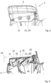
- the bracket 13 is for example located between the internal side 23 and the sensors 9 transversally to the reference plane 19 as depicted in the variant of figures 1 and 2 according which there is no extension portion 11.
- the bracket 13 cooperates by surface cooperation with the internal side 15.
- the sensors 9 can be located between the internal side 15 and the extension portion 11 in the variant depicted in figures 3 and 4 .
- the extension portion 11 can present some portions that can cooperate by surface cooperation with the internal side 15.
- the car access assembly 1 comprises both the handle 3 with the extension portion 11 and the bracket 13, the bracket 13 being configured to cooperate with said extension portion 11.
- the bracket 13 or alternatively the extension portion 11 can cooperate with internal side 15 depending on the construction choice.
- extension portion 11 and/or the bracket 13 are respectively in contact with the sensors 9 and with the internal side 15.
- the extension portion 11 and/or the bracket 13 presents two recess 27 adapted to receive the sensors 9.
- the bracket 13 is configured to be clipped to handle 3 as shown on figure 1 .
- the fixing mechanism 21 comprises, for each sensor 9, a main fastener 29 which is configured to extend according to a main direction 31 transversal to the reference plane 19, the main fastener 29 being configured to cooperate with the corresponding sensor 9, the extension portion 11 and/or bracket 13, the part 17 of the car and the handle 3.
- the main fasteners 29 allow a good hold in place of the sensors 9. Therefore, each sensor 9 is maintained in position with respect to the part 17 of the car and is able to perceive the constraint applied on the handle 3.
- a support 33 for a corresponding sensor 9, the extension portion 11 and/or bracket 13, the part 17 of the car door 5 each presents a corresponding through opening for the passage of the corresponding main fastener 29.
- the through openings are aligned so that the main fastener 29 is able to pass through.
- the handle 3 comprises a socket 35 adapted to cooperate with the main fastener 29.
- Each main fastener 29 comprises a head 37 configured to cooperate with the support 33 and/or the extension portion 11 and/or bracket 13.
- each sensor 9 comprises two strain gauges 25 mounted on the support 33.
- the support 33 is constituted of a metal material.
- the main fastener 29 is a screw and the socket 35 includes a threaded portion 39.
- the threaded portion 39 can be a threaded insert introduced in an orifice of the handle 3 as shown on figure 6 .
- the support 33 has at least one attaching portion 41 configured to be fixed to the extension portion 11 and/or bracket 13 thanks to a corresponding additional fastener 43 of the fixing mechanism 21.
- the at least one attaching portion 41 is an orifice or a slot configured for receiving the corresponding additional fastener 43 which is for example a screw, possibly with mounting ring(s).
- the support 33 presents two attaching portions 41, the strain gauges 25 being located between the two attaching portions 41 according to a longitudinal direction 45 of the support 33.
- the through opening of the support 33 is located between the two strain gauges 25 according to the longitudinal direction 45 of the support 33.
- Each sensor 9 comprises two strain gauges 25 mounted on the support 33.
- the support 33 is constituted of a metal material.
- the car access assembly 1 can comprise an additional fixing element for fixing the handle on the part 17 of the car.
- the additional fixing element is a screw configured to be cooperating with the handle and with the part of the car.
- the electronic sensing unit 7 comprises two distinct sensors and two corresponding fixing mechanisms 21 in figures 1 to 5 . In these configurations both sensors are located on the same side than the internal side 15 as described above.
- the electronic sensing unit 7 comprises a further sensor 47 mounted on the external side 23 of the part 17 of the car, the car access assembly 1 including a further fixing element 49 for maintaining the further sensor 47 on the external side 23.
- the further sensor 47 is identical to the above described sensor 9, only its location is different. The fact of having a further sensor 47 at another location improves the quality of the acquisition of solicitation of the handle 3.
- the further fixing element 49 includes a first part 51 adapted to be received in a further recess of the handle 3 and a second part 53 configured to cooperate with the first part 51.
- the first part 51 is a nut and the second part 53 is a screw extending transverse to the reference plane 19.
- the extension portion 11 and/or bracket 13, the part 17 of the car and the further sensor 47 each presenting a through opening for the passage of the screw.
- Each strain gauge 25 is linked to a signal transmitting device of the car access assembly (not represented).
- Each signal transmitting device comprises electrical wire(s) or flexible printed circuit board(s) configured to transmit a signal from the sensor. Wires can be shielded or not.
- the handle 3 is an outside handle of the car for example on the driver side.
- the car access assembly includes the car door 5.
Landscapes
- Lock And Its Accessories (AREA)
Priority Applications (4)
| Application Number | Priority Date | Filing Date | Title |
|---|---|---|---|
| EP22194517.3A EP4336004B1 (fr) | 2022-09-08 | 2022-09-08 | Ensemble d'accès de voiture comprenant une poignée de portière de voiture |
| CN202311147967.8A CN117661936A (zh) | 2022-09-08 | 2023-09-06 | 包括车门把手的车进入组件 |
| JP2023144953A JP2024039008A (ja) | 2022-09-08 | 2023-09-07 | 自動車用ドアのハンドルを備える自動車用アクセスアセンブリ |
| US18/463,643 US20240084623A1 (en) | 2022-09-08 | 2023-09-08 | Car access assembly including a handle of a car door |
Applications Claiming Priority (1)
| Application Number | Priority Date | Filing Date | Title |
|---|---|---|---|
| EP22194517.3A EP4336004B1 (fr) | 2022-09-08 | 2022-09-08 | Ensemble d'accès de voiture comprenant une poignée de portière de voiture |
Publications (2)
| Publication Number | Publication Date |
|---|---|
| EP4336004A1 true EP4336004A1 (fr) | 2024-03-13 |
| EP4336004B1 EP4336004B1 (fr) | 2025-10-29 |
Family
ID=83270764
Family Applications (1)
| Application Number | Title | Priority Date | Filing Date |
|---|---|---|---|
| EP22194517.3A Active EP4336004B1 (fr) | 2022-09-08 | 2022-09-08 | Ensemble d'accès de voiture comprenant une poignée de portière de voiture |
Country Status (4)
| Country | Link |
|---|---|
| US (1) | US20240084623A1 (fr) |
| EP (1) | EP4336004B1 (fr) |
| JP (1) | JP2024039008A (fr) |
| CN (1) | CN117661936A (fr) |
Citations (5)
| Publication number | Priority date | Publication date | Assignee | Title |
|---|---|---|---|---|
| US20020108310A1 (en) * | 2001-02-14 | 2002-08-15 | Clemens Schroer | Vehicle door for a convertible |
| DE102005049027A1 (de) * | 2005-10-11 | 2007-04-12 | Huf Hülsbeck & Fürst Gmbh & Co. Kg | Vorrichtung zum Öffnen von Schlössern an Türen oder Klappen bei Fahrzeugen |
| US20140292004A1 (en) * | 2013-04-01 | 2014-10-02 | Magna Mirrors Of America, Inc. | Vehicle door handle system |
| US20160123045A1 (en) * | 2014-10-29 | 2016-05-05 | Adac Plastics, Inc. | Decoupled handle switch |
| DE102016123724A1 (de) * | 2016-12-07 | 2018-06-07 | Witte Automotive Gmbh | Türgriffsystem |
Family Cites Families (1)
| Publication number | Priority date | Publication date | Assignee | Title |
|---|---|---|---|---|
| US12385297B2 (en) * | 2022-02-16 | 2025-08-12 | Magna Mirrors Of America, Inc. | System and method for an applique with deployable handle |
-
2022
- 2022-09-08 EP EP22194517.3A patent/EP4336004B1/fr active Active
-
2023
- 2023-09-06 CN CN202311147967.8A patent/CN117661936A/zh active Pending
- 2023-09-07 JP JP2023144953A patent/JP2024039008A/ja active Pending
- 2023-09-08 US US18/463,643 patent/US20240084623A1/en active Pending
Patent Citations (5)
| Publication number | Priority date | Publication date | Assignee | Title |
|---|---|---|---|---|
| US20020108310A1 (en) * | 2001-02-14 | 2002-08-15 | Clemens Schroer | Vehicle door for a convertible |
| DE102005049027A1 (de) * | 2005-10-11 | 2007-04-12 | Huf Hülsbeck & Fürst Gmbh & Co. Kg | Vorrichtung zum Öffnen von Schlössern an Türen oder Klappen bei Fahrzeugen |
| US20140292004A1 (en) * | 2013-04-01 | 2014-10-02 | Magna Mirrors Of America, Inc. | Vehicle door handle system |
| US20160123045A1 (en) * | 2014-10-29 | 2016-05-05 | Adac Plastics, Inc. | Decoupled handle switch |
| DE102016123724A1 (de) * | 2016-12-07 | 2018-06-07 | Witte Automotive Gmbh | Türgriffsystem |
Also Published As
| Publication number | Publication date |
|---|---|
| US20240084623A1 (en) | 2024-03-14 |
| CN117661936A (zh) | 2024-03-08 |
| JP2024039008A (ja) | 2024-03-21 |
| EP4336004B1 (fr) | 2025-10-29 |
Similar Documents
| Publication | Publication Date | Title |
|---|---|---|
| EP4336003B1 (fr) | Ensemble d'accès de vehicule avec unité de détection électronique pour une poignée fixée sur une portière de voiture | |
| EP2998166B1 (fr) | Système de fixation utilisable pour des connecteurs | |
| US5040387A (en) | Vehicle brake lock assembly | |
| US7690279B2 (en) | Vehicle-pedal backward-displacement preventing device | |
| CN110454010A (zh) | 车辆用门闩的解除装置 | |
| EP4336004B1 (fr) | Ensemble d'accès de voiture comprenant une poignée de portière de voiture | |
| US20170350172A1 (en) | Lock device | |
| EP0765782A2 (fr) | Prétensionneur de boucle de ceinture de sécurité | |
| CN112384671A (zh) | 车门的外把手装置 | |
| KR100810172B1 (ko) | 센서 장치 및 센서 장치를 장착판에 배치하는 방법 | |
| KR20090064954A (ko) | 화물차량의 안전 공구함 | |
| US6837520B2 (en) | Fastening assembly for a safety belt reactor comprising a reinforcement plate | |
| US7264290B2 (en) | Mounting bracket assembly | |
| EP4512982A1 (fr) | Ensemble d'accès pour voiture avec deux jauges de contrainte orientées différemment | |
| US7618077B2 (en) | Windshield wiper device | |
| JP2024035826A (ja) | 自動車用ドアのセンサーとして使用される歪ゲージモジュールを有するハンドル | |
| US12297671B2 (en) | Vehicular door handle assembly | |
| KR101802369B1 (ko) | 자동차용 잠금장치 | |
| EP0390210A1 (fr) | Dispositif de verrouillage de sécurité pour sélecteur d'une boîte de vitesses automatique | |
| US20250033545A1 (en) | Vehicle part retaining structure | |
| US9168892B2 (en) | Detector device for detecting the locking state of a seat belt lock, insert, and seat belt lock equipped with a detector device | |
| EP1087081A1 (fr) | Serrures à sécurité enfants pour véhicule | |
| CN112796593A (zh) | 模块化开关组件 | |
| KR0139714Y1 (ko) | 자동차용 트렁크 리드의 개방장치 | |
| WO2012171212A1 (fr) | Support pour le montage d'une antenne d'accès et démarrage mains libres et plancher de véhicule supportant ledit support |
Legal Events
| Date | Code | Title | Description |
|---|---|---|---|
| PUAI | Public reference made under article 153(3) epc to a published international application that has entered the european phase |
Free format text: ORIGINAL CODE: 0009012 |
|
| STAA | Information on the status of an ep patent application or granted ep patent |
Free format text: STATUS: REQUEST FOR EXAMINATION WAS MADE |
|
| 17P | Request for examination filed |
Effective date: 20220908 |
|
| AK | Designated contracting states |
Kind code of ref document: A1 Designated state(s): AL AT BE BG CH CY CZ DE DK EE ES FI FR GB GR HR HU IE IS IT LI LT LU LV MC MK MT NL NO PL PT RO RS SE SI SK SM TR |
|
| GRAP | Despatch of communication of intention to grant a patent |
Free format text: ORIGINAL CODE: EPIDOSNIGR1 |
|
| STAA | Information on the status of an ep patent application or granted ep patent |
Free format text: STATUS: GRANT OF PATENT IS INTENDED |
|
| INTG | Intention to grant announced |
Effective date: 20250611 |
|
| GRAS | Grant fee paid |
Free format text: ORIGINAL CODE: EPIDOSNIGR3 |
|
| GRAA | (expected) grant |
Free format text: ORIGINAL CODE: 0009210 |
|
| STAA | Information on the status of an ep patent application or granted ep patent |
Free format text: STATUS: THE PATENT HAS BEEN GRANTED |
|
| AK | Designated contracting states |
Kind code of ref document: B1 Designated state(s): AL AT BE BG CH CY CZ DE DK EE ES FI FR GB GR HR HU IE IS IT LI LT LU LV MC MK MT NL NO PL PT RO RS SE SI SK SM TR |
|
| REG | Reference to a national code |
Ref country code: CH Ref legal event code: F10 Free format text: ST27 STATUS EVENT CODE: U-0-0-F10-F00 (AS PROVIDED BY THE NATIONAL OFFICE) Effective date: 20251029 Ref country code: GB Ref legal event code: FG4D |
|
| REG | Reference to a national code |
Ref country code: DE Ref legal event code: R096 Ref document number: 602022023818 Country of ref document: DE |
|
| REG | Reference to a national code |
Ref country code: IE Ref legal event code: FG4D |
|
| REG | Reference to a national code |
Ref country code: NL Ref legal event code: MP Effective date: 20251029 |
|
| PG25 | Lapsed in a contracting state [announced via postgrant information from national office to epo] |
Ref country code: ES Free format text: LAPSE BECAUSE OF FAILURE TO SUBMIT A TRANSLATION OF THE DESCRIPTION OR TO PAY THE FEE WITHIN THE PRESCRIBED TIME-LIMIT Effective date: 20251029 |
|
| REG | Reference to a national code |
Ref country code: LT Ref legal event code: MG9D |
|
| PG25 | Lapsed in a contracting state [announced via postgrant information from national office to epo] |
Ref country code: NO Free format text: LAPSE BECAUSE OF FAILURE TO SUBMIT A TRANSLATION OF THE DESCRIPTION OR TO PAY THE FEE WITHIN THE PRESCRIBED TIME-LIMIT Effective date: 20260129 |
|
| PG25 | Lapsed in a contracting state [announced via postgrant information from national office to epo] |
Ref country code: AT Free format text: LAPSE BECAUSE OF FAILURE TO SUBMIT A TRANSLATION OF THE DESCRIPTION OR TO PAY THE FEE WITHIN THE PRESCRIBED TIME-LIMIT Effective date: 20251029 Ref country code: FI Free format text: LAPSE BECAUSE OF FAILURE TO SUBMIT A TRANSLATION OF THE DESCRIPTION OR TO PAY THE FEE WITHIN THE PRESCRIBED TIME-LIMIT Effective date: 20251029 Ref country code: HR Free format text: LAPSE BECAUSE OF FAILURE TO SUBMIT A TRANSLATION OF THE DESCRIPTION OR TO PAY THE FEE WITHIN THE PRESCRIBED TIME-LIMIT Effective date: 20251029 |
|
| REG | Reference to a national code |
Ref country code: AT Ref legal event code: MK05 Ref document number: 1851734 Country of ref document: AT Kind code of ref document: T Effective date: 20251029 |
|
| PG25 | Lapsed in a contracting state [announced via postgrant information from national office to epo] |
Ref country code: NL Free format text: LAPSE BECAUSE OF FAILURE TO SUBMIT A TRANSLATION OF THE DESCRIPTION OR TO PAY THE FEE WITHIN THE PRESCRIBED TIME-LIMIT Effective date: 20251029 |
|
| PG25 | Lapsed in a contracting state [announced via postgrant information from national office to epo] |
Ref country code: RS Free format text: LAPSE BECAUSE OF FAILURE TO SUBMIT A TRANSLATION OF THE DESCRIPTION OR TO PAY THE FEE WITHIN THE PRESCRIBED TIME-LIMIT Effective date: 20260129 |
|
| PG25 | Lapsed in a contracting state [announced via postgrant information from national office to epo] |
Ref country code: IS Free format text: LAPSE BECAUSE OF FAILURE TO SUBMIT A TRANSLATION OF THE DESCRIPTION OR TO PAY THE FEE WITHIN THE PRESCRIBED TIME-LIMIT Effective date: 20260228 |
|
| PG25 | Lapsed in a contracting state [announced via postgrant information from national office to epo] |
Ref country code: PT Free format text: LAPSE BECAUSE OF FAILURE TO SUBMIT A TRANSLATION OF THE DESCRIPTION OR TO PAY THE FEE WITHIN THE PRESCRIBED TIME-LIMIT Effective date: 20260302 |
|
| PG25 | Lapsed in a contracting state [announced via postgrant information from national office to epo] |
Ref country code: PL Free format text: LAPSE BECAUSE OF FAILURE TO SUBMIT A TRANSLATION OF THE DESCRIPTION OR TO PAY THE FEE WITHIN THE PRESCRIBED TIME-LIMIT Effective date: 20251029 |
|
| PG25 | Lapsed in a contracting state [announced via postgrant information from national office to epo] |
Ref country code: LV Free format text: LAPSE BECAUSE OF FAILURE TO SUBMIT A TRANSLATION OF THE DESCRIPTION OR TO PAY THE FEE WITHIN THE PRESCRIBED TIME-LIMIT Effective date: 20251029 |