EP4336053A2 - Hochleistungs-airlift-pumpe - Google Patents
Hochleistungs-airlift-pumpe Download PDFInfo
- Publication number
- EP4336053A2 EP4336053A2 EP23216508.4A EP23216508A EP4336053A2 EP 4336053 A2 EP4336053 A2 EP 4336053A2 EP 23216508 A EP23216508 A EP 23216508A EP 4336053 A2 EP4336053 A2 EP 4336053A2
- Authority
- EP
- European Patent Office
- Prior art keywords
- airlift pump
- gas
- mixing chamber
- pump
- injection port
- Prior art date
- Legal status (The legal status is an assumption and is not a legal conclusion. Google has not performed a legal analysis and makes no representation as to the accuracy of the status listed.)
- Withdrawn
Links
Images


Classifications
-
- C—CHEMISTRY; METALLURGY
- C02—TREATMENT OF WATER, WASTE WATER, SEWAGE, OR SLUDGE
- C02F—TREATMENT OF WATER, WASTE WATER, SEWAGE, OR SLUDGE
- C02F3/00—Biological treatment of water, waste water, or sewage
- C02F3/02—Aerobic processes
- C02F3/12—Activated sludge processes
- C02F3/22—Activated sludge processes using circulation pipes
- C02F3/223—Activated sludge processes using circulation pipes using "air-lift"
-
- F—MECHANICAL ENGINEERING; LIGHTING; HEATING; WEAPONS; BLASTING
- F04—POSITIVE - DISPLACEMENT MACHINES FOR LIQUIDS; PUMPS FOR LIQUIDS OR ELASTIC FLUIDS
- F04F—PUMPING OF FLUID BY DIRECT CONTACT OF ANOTHER FLUID OR BY USING INERTIA OF FLUID TO BE PUMPED; SIPHONS
- F04F5/00—Jet pumps, i.e. devices in which flow is induced by pressure drop caused by velocity of another fluid flow
- F04F5/14—Jet pumps, i.e. devices in which flow is induced by pressure drop caused by velocity of another fluid flow the inducing fluid being elastic fluid
- F04F5/24—Jet pumps, i.e. devices in which flow is induced by pressure drop caused by velocity of another fluid flow the inducing fluid being elastic fluid displacing liquids, e.g. containing solids, or liquids and elastic fluids
-
- B—PERFORMING OPERATIONS; TRANSPORTING
- B01—PHYSICAL OR CHEMICAL PROCESSES OR APPARATUS IN GENERAL
- B01F—MIXING, e.g. DISSOLVING, EMULSIFYING OR DISPERSING
- B01F23/00—Mixing according to the phases to be mixed, e.g. dispersing or emulsifying
- B01F23/20—Mixing gases with liquids
- B01F23/23—Mixing gases with liquids by introducing gases into liquid media, e.g. for producing aerated liquids
- B01F23/231—Mixing gases with liquids by introducing gases into liquid media, e.g. for producing aerated liquids by bubbling
- B01F23/23105—Arrangement or manipulation of the gas bubbling devices
- B01F23/2312—Diffusers
- B01F23/23121—Diffusers having injection means, e.g. nozzles with circumferential outlet
-
- B—PERFORMING OPERATIONS; TRANSPORTING
- B01—PHYSICAL OR CHEMICAL PROCESSES OR APPARATUS IN GENERAL
- B01F—MIXING, e.g. DISSOLVING, EMULSIFYING OR DISPERSING
- B01F23/00—Mixing according to the phases to be mixed, e.g. dispersing or emulsifying
- B01F23/20—Mixing gases with liquids
- B01F23/23—Mixing gases with liquids by introducing gases into liquid media, e.g. for producing aerated liquids
- B01F23/232—Mixing gases with liquids by introducing gases into liquid media, e.g. for producing aerated liquids using flow-mixing means for introducing the gases, e.g. baffles
- B01F23/2323—Mixing gases with liquids by introducing gases into liquid media, e.g. for producing aerated liquids using flow-mixing means for introducing the gases, e.g. baffles by circulating the flow in guiding constructions or conduits
- B01F23/23231—Mixing gases with liquids by introducing gases into liquid media, e.g. for producing aerated liquids using flow-mixing means for introducing the gases, e.g. baffles by circulating the flow in guiding constructions or conduits being at least partially immersed in the liquid, e.g. in a closed circuit
- B01F23/232311—Mixing gases with liquids by introducing gases into liquid media, e.g. for producing aerated liquids using flow-mixing means for introducing the gases, e.g. baffles by circulating the flow in guiding constructions or conduits being at least partially immersed in the liquid, e.g. in a closed circuit the conduits being vertical draft pipes with a lower intake end and an upper exit end
-
- B—PERFORMING OPERATIONS; TRANSPORTING
- B01—PHYSICAL OR CHEMICAL PROCESSES OR APPARATUS IN GENERAL
- B01F—MIXING, e.g. DISSOLVING, EMULSIFYING OR DISPERSING
- B01F23/00—Mixing according to the phases to be mixed, e.g. dispersing or emulsifying
- B01F23/80—After-treatment of the mixture
- B01F23/803—Venting, degassing or ventilating of gases, fumes or toxic vapours from the mixture
-
- C—CHEMISTRY; METALLURGY
- C02—TREATMENT OF WATER, WASTE WATER, SEWAGE, OR SLUDGE
- C02F—TREATMENT OF WATER, WASTE WATER, SEWAGE, OR SLUDGE
- C02F1/00—Treatment of water, waste water, or sewage
- C02F1/20—Treatment of water, waste water, or sewage by degassing, i.e. liberation of dissolved gases
-
- C—CHEMISTRY; METALLURGY
- C02—TREATMENT OF WATER, WASTE WATER, SEWAGE, OR SLUDGE
- C02F—TREATMENT OF WATER, WASTE WATER, SEWAGE, OR SLUDGE
- C02F3/00—Biological treatment of water, waste water, or sewage
- C02F3/02—Aerobic processes
- C02F3/12—Activated sludge processes
- C02F3/20—Activated sludge processes using diffusers
- C02F3/201—Perforated, resilient plastic diffusers, e.g. membranes, sheets, foils, tubes, hoses
-
- F—MECHANICAL ENGINEERING; LIGHTING; HEATING; WEAPONS; BLASTING
- F04—POSITIVE - DISPLACEMENT MACHINES FOR LIQUIDS; PUMPS FOR LIQUIDS OR ELASTIC FLUIDS
- F04F—PUMPING OF FLUID BY DIRECT CONTACT OF ANOTHER FLUID OR BY USING INERTIA OF FLUID TO BE PUMPED; SIPHONS
- F04F1/00—Pumps using positively or negatively pressurised fluid medium acting directly on the liquid to be pumped
- F04F1/18—Pumps using positively or negatively pressurised fluid medium acting directly on the liquid to be pumped the fluid medium being mixed with, or generated from the liquid to be pumped
- F04F1/20—Pumps using positively or negatively pressurised fluid medium acting directly on the liquid to be pumped the fluid medium being mixed with, or generated from the liquid to be pumped specially adapted for raising liquids from great depths, e.g. in wells
-
- F—MECHANICAL ENGINEERING; LIGHTING; HEATING; WEAPONS; BLASTING
- F04—POSITIVE - DISPLACEMENT MACHINES FOR LIQUIDS; PUMPS FOR LIQUIDS OR ELASTIC FLUIDS
- F04F—PUMPING OF FLUID BY DIRECT CONTACT OF ANOTHER FLUID OR BY USING INERTIA OF FLUID TO BE PUMPED; SIPHONS
- F04F5/00—Jet pumps, i.e. devices in which flow is induced by pressure drop caused by velocity of another fluid flow
- F04F5/44—Component parts, details, or accessories not provided for in, or of interest apart from, groups F04F5/02 - F04F5/42
- F04F5/46—Arrangements of nozzles
- F04F5/465—Arrangements of nozzles with supersonic flow
-
- C—CHEMISTRY; METALLURGY
- C02—TREATMENT OF WATER, WASTE WATER, SEWAGE, OR SLUDGE
- C02F—TREATMENT OF WATER, WASTE WATER, SEWAGE, OR SLUDGE
- C02F2103/00—Nature of the water, waste water, sewage or sludge to be treated
- C02F2103/20—Nature of the water, waste water, sewage or sludge to be treated from animal husbandry
Definitions
- the invention relates generally to air-lift pumps and, more particularly, to vertically orientated lift pumps for the recirculation of fluid in aquaculture systems.
- Air-lift pumps are self-contained liquid transport devices capable of moving large quantities of water. They are mechanical devices that are usually vertically oriented in the form of a tube or pipe, where the lower portion of the tube is immersed in a liquid medium. The submerged pipe is fitted with an air injection source near the bottom submerged end.
- gas is simultaneously streamed into the liquid.
- the injection of the gas may be done via a commercial product known as an air-stone.
- This injection of gas causes the density of the water to drop, which causes the water to rise within the tube. This then enables or draws other water to enter the tube from the bottom end.
- the specific gravity of the gas/water mixture lowers, causing the gas/water mixture to rise through the tube and the "heavier" water takes its place at the bottom of the tube before it is also injected with gas.
- As less-dense water rises in the tube above the water-line level of the tank outside the vertically-oriented tube it will reach one or more ports where the liquid and gas are ejected.
- This disclosure describes a device for use between an injection port and a mixing chamber within an airlift pump, the device comprising: a planar plate with multiple holes extending therethrough, the holes dimensioned to direct the gas into multiple micro-streams for streaming air from the injection port into the mixing chamber.
- an airlift pump comprising:
- Airlift pump 10 An example embodiment of an airlift pump 10, a gas streaming device 50 for streaming air into airlift pump 10, and their use will be discussed. Airlift pump 10 will first be described.
- airlift pump 10 generally includes an injection port 12, an injection chamber 14, a mixing chamber 16, a lift tube 18, an ejection port 20, and gas streaming device 50 positioned between injection port 12 and mixing chamber 16.
- Injection port 12 is positioned at one end of airlift pump 10 and is fluidly coupled to an air supply 22 and connected to injection chamber 14.
- the location and dimension of injection port 12 may vary.
- an airlift pump having a 6-inch diameter may have a 2-inch diameter injection port to allow a sufficient volume of water to enter airlift pump 10 without a significant pressure drop.
- an airlift pump having a 1-inch diameter may have a 1/8-inch diameter injection port.
- injection port 12 may be positioned at the bottom or on a side of one end of airlift pump 10, so long as injection port 12 is located close to the bottom of the tank to maximize lift capacity.
- Injection chamber 14 is, in turn, fluidly connected to mixing chamber 16 with gas streaming device 50 positioned therebetween.
- gas streaming device 50 is sealed from the surrounding liquid and is orientated horizontally or laterally between injection chamber 14 and mixing chamber 16.
- the height of gas streaming device 50 is as small as premanufactured parts may permit in order to avoid positioning a large air pocket near the bottom of the tank that may cause the unit to float.
- the diameter of injection chamber 14 would generally correspond with the diameter of its corresponding airlift pump. For example, a 6-inch diameter airlift pump would have a 6-inch diameter injection chamber.
- Mixing chamber 16, as shown, is a cylindrical tube with perforations in its walls 17.
- the height of mixing chamber 16 may vary, but it is typically, 8-12 inches.
- mixing chamber 12 is where the surrounding water/liquid will be drawn into airlift pump 10, in order to maximize circulation, mixing chamber 12 is generally positioned as close to the bottom of the tank as possible.
- the exact size and arrangement of the perforations may vary, in order to keep particulate and organisms out of airlift pump 10. That being said, the perforations typically form at least 60% open space for water or liquid to enter airlift pump 10.
- Lift tube 18 is fluidly connected to, and extends from, mixing chamber 16.
- Ejection port 20 is, in turn, is fluidly connected to and extends from lift tube 18. In this manner, ejection port 20 is positioned at the opposite end of airlift pump 10, opposite injection port 12. Ejection port 20 has a gas discharge aperture 24 orientated parallel to lift tube 18, and a liquid discharge aperture 26 orientated generally perpendicular to lift tube 18. Airlift pump 10 also includes a fluid flow sensor 32 integrated into ejection port 20.
- airlift pump 10 further has a bacterial media 28 suspended within lift tube 18 or attached to the inner wall lift tube 18.
- injection chamber 14 may contain a diffuser, a baffle, or other mechanical means to promote uniform flow through the face of gas streaming device 50.
- the positioning of one or more injection ports 12 may be another mechanical means to promote even flow through gas steaming device 50.
- airlift pump 10 includes multiple gas injection ports proximate the bottom of lift pump 10, which would be connected with one or more injection chambers.
- airlift pump 10 would include multiple gas streaming devices, a gas flow control valve and a following flow rate sensor.
- the gas flow control valve and flow rate sensors would be configured regulate gas flow to the multiple gas streaming devices.
- a mechanical apparatus such as a pump, is integrated with injection port 12 to enable adjustment and control of the gas pressure directed into injection chamber 14.
- airlift pump 10 would have components with non- circular cross-sections.
- the height and/or radius of lift tube 18 may be altered to maximize the removal of gas from the liquid medium.
- the height and radius of lift tube 18 may be modified to accommodate different tank dimensions and air sources.
- Airlift pump 10 may also be packaged and integrated with a transportable tank containing the liquid medium to be remediated by airlift pump 10.
- Gas streaming device 50 will now be described in detail and is shown in isolation in Figures 2 and 3 .
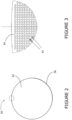
- Gas streaming device 50 comprises a body with multiple holes or perforations 52 having a diameter of 0.35mm. As shown, the body is a circular plate 54 having a first face, an opposed second face, and a perimeter 56.
- Plate 54 is formed from a solid hydrophobic material which can be cleaned and sterilized. Plate 54 has a thickness of 12.7mm.
- Multiple holes 52 extend from the first face to the second face and are evenly spaced throughout plate 54.
- multiple holes 52 are spaced 0.55mm, center to center, apart from one another in a grid pattern.
- Multiple holes 52 are also positioned at least 0.5mm from perimeter 56 of plate 54.
- multiple holes 52 in plate 54 contain a helical groove pattern, or rifling.
- the rifling is orientated at a 30-degree angle with respect to the longitudinal axis of each hole.
- perforations 52 generally do not change relative to the diameter or height of airlift pump 10. However, in some examples, the size and configuration of perforations 52 may vary. For example, the holes or perforations 52 may have diameters generally between 0.2mm-0.4mm.
- multiple holes 52 are spaced 0.5mm-0.6mm apart, center to center, from one another in a grid pattern and plate 54 has a thickness between 12-13mm.
- multiple holes 52 are unevenly spaced throughout plate 102.
- the body is composed of packed fiber which may be oriented vertically and/or horizontally to force the gas to flow around the fiber.
- the fiber would be hydrophobic and packed within perforated plates.
- Air lift pump 10 Movement of fluid through the use of airlift pump 10 is indicated by the arrows in Figure 1 .
- the movement of gas is indicated by dashed arrows, while movement of water is indicated by solid arrows.
- air lift pump 10 is positioned within a body of water 100 in tank 102 such that injection chamber 14 and mixing chamber 16 are submerged while ejection port 20 is above the water line.
- Pressurized air is injected by air supply 22 through injection port 12 and into injection chamber 14. From there, the air is directed through gas streaming device 50 into mixing chamber 16. Gas streaming device 50 forces the gas or air into multiple streams as it enters mixing chamber 16.
- the diameter and spacing of multiple holes 52 in plate 54 are set to generate, uniform small gas streams at the bottom of the pump that are as vertical as possible so as to provide uniform lift.
- the helical groove pattern, or rifling, of multiple holes 52 also helps to gyroscopically stabilize the gas flow as it leaves plate 54. These features help to minimize the merging of gas streams and to minimize the leakage of gas out of the perforated walls 17 of mixing chamber 16.
- Plate 54 is also orientated horizontally within airlift pump 10. In this manner, multiple holes 52 are orientated generally parallel with the longitudinal orientation of airlift pump 10, which serves to help ensure the longest possible narrow vertical path for each gas stream as they leave plate 54.
- the uniformity of the gas streams helps to impart a more uniform lift to the liquid from the gas.
- a vertical stream is also beneficial to help prevent air streams from merging to form larger bubbles, which would provide less uniform lift.
- Bacterial media 28 enables bacteria to be used to remediate targeted impurities within the liquid such as ammonia.
- the height and/or radius of lift tube 18 is adjusted to accommodate the depth of the surrounding liquid medium and the desired lift of the liquid medium by the pump above the water line.
- Airlift pump 10 may be used simultaneously with one or more saturator systems in a body of water.
- Saturator systems are configured to conduct a gas exchange with an aqueous-phase liquid inline with the same body of water.
- the saturator systems are adapted to dissolve oxygen into the water and remove carbon dioxide, such that the overall gas pressure within the fluid is relatively unchanged.
- An example of such a saturator system is disclosed in US 62/610,675 .
- Each saturator system uses one or more gas infusion devices to dissolve oxygen into the water.
- Each gas infusion device has a fibre module array situated between its ends where the fibre module array is made up of a polymer coated microporous fiber material.
- An example of such a gas infusion device is found in US7537200 , to Glassford, October 31, 2003.
- the saturator system oxygenates the body of water and removes carbon dioxide, while the one or more airlift pumps 10 also remove the dissolved C0 2 and remediates the ammonia to form nitrate.
- Such a combined system may further include one or more oxygen tanks connected to the saturator system for supplying oxygen to the saturator system, and a compressor coupled to airlift pumps 10 to supply ambient air to generate the lift.
- Such a system may also have a gas regulator operatively coupled between the oxygen tanks and the saturator system to regulate the flow of gas into the saturator system, a dissolved oxygen sensor positioned within the body of water, a saturator feed pump in fluid communication with the body of water, adapted to draw and direct water from the body of water into the saturator system, and an ammonia sensor positioned within the body of water.
- a gas regulator operatively coupled between the oxygen tanks and the saturator system to regulate the flow of gas into the saturator system
- a dissolved oxygen sensor positioned within the body of water
- a saturator feed pump in fluid communication with the body of water, adapted to draw and direct water from the body of water into the saturator system
- an ammonia sensor positioned within the body of water.
- a control and monitoring system may be in place to communicate with, control and coordinate each of the above components.
- the compressor can be activated to engage airlift pumps 10 in response to the detected concentration of ammonia rising above a maximum level.
- the compressor may then be disengaged to deactivate airlift pumps 10 in response to the detected concentration of ammonia falling below a minimum level.
- the gas regulator and the saturator feed pump may be activated and controlled in response to the detected concentration of oxygen falling below a minimum level.
- the gas regulator and the saturator feed pump may also be deactivated accordingly.
- An advantage of the use of the present gas streaming device 50 in airlift pump 10 is that it is able to lift 3 or more unit volumes of liquid using only one unit volume of gas the same distance as a conventional lift pump.
- the increased efficiency may also enable airlift pump 10 to be economic in other applications where it is desirable to lift a liquid or induce flow.
- Airlift pump 10 was attached to an air source with a measurable flow, and then inserted into the body of water in the tank, ensuring that ejection port 20 was above the water line, noting that the exact location would depend on the airlift pump unit.
- Air is then supplied to airlift pump 10 and the air pressure within injection chamber 14 underneath gas streaming device 10 is measured to determine actual air flow.
- C0 2 levels in the tank were recorded over the course of the experiment.
- the C0 2 levels in the tank naturally will not be homogeneous, so it was assumed that the highest C0 2 level in the tank was at the vacuum or suction area within mixing chamber 16 and the lowest C0 2 level was at liquid discharge aperture 26. An average of these two values was used to be representative of the whole tank.
- the flow of water out of liquid discharge aperture 26 was measured along with the temperature and salinity of the water within the tank. These measurements were used to create a profile of the tank concentration of C0 2 over time, as well as the efficiency of airlift pump 10 (using the known amount of water leaving liquid discharge aperture 26 and the concentration in the tank. The instantaneous rate of change in C0 2 (amount removed at any given concentration) was determined by taking the derivative of the concentration over time.
- Test Method 2 A second test method (Test Method 2), largely similar to Test Method 1, was used in situations where it was not possible to measure the water flow out of the airlift pump 10. This method involved continuously adding a known quantity of C0 2 to the tank while airlift pump 10 was in operation until equilibrium was achieved (i.e. the point at which the C0 2 being added was equal to the C02 being removed). By determining the concentration at both the top and bottom of the airlift pump 10, the flowrate of water was calculated.
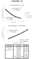
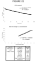
- Figure 4 is a sample table explaining the terms and units of measurement in the tables of Figures 5 to 26 .
- the first graph in each Figure shows the decrease in C0 2 levels over the course of the trial (using Test Method 1).
- the second graph in each Figure shows the calculated rate of change in C0 2 for any concentration using the airlift pump at the parameters specified in the corresponding table.
- Each corresponding table shows all the fixed settings for the particular trial as well as the calculated liquid to gas ratio and the calculated percent removal.
- the first graph in each Figure shows the decrease in C02 levels over the course of the trial measurements, which were taken at both the top and bottom of the lift (using Test Method 1).
- the second graph in each Figure shows the calculated rate of change in C02 for any concentration using the lift at the parameters specified in the corresponding table.
- Each table shows all the fixed the settings for the respective trial as well as the calculated liquid to gas ratio and the calculated percent removal.
- the first graph shows the decrease in C02 levels over the course of the trial (using Test Method 1).
- the second graph shows the calculated rate of change in C02 for any concentration using the lift at the parameters specified in the table.
- the table shows all the fixed settings for the trial as well as the calculated liquid to gas ratio and the calculated percent removal.
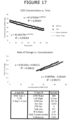
- the first graph shows the decrease in C02 levels over the course of the trial (using Test Method 1). This is a comparison of the old and new disc (or gas streaming device) styles and shows little difference in performance at the given levels.
- the old disc style was a "disc” that consisted of numerous hydrophobic hollow fibers held in place with epoxy to generate a similar effect as gas streaming device 50.
- the holes in the old disc were not always uniform or strait, or even always open, which naturally caused a drop in the efficiency and quality of gas diffusion.
- the second graph shows the calculated rate of change in C02 for any concentration using the airlift pump at the parameters specified in the table.
- the table shows all the fixed the settings for the trial as well as the calculated liquid to gas ratio and the calculated percent removal.
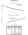
- the first graph in each Figure shows the decrease in C0 2 levels over the course of the trial (using Test Method 1).
- the second graph in each Figure shows the calculated rate of change in C0 2 for any concentration using the lift at the parameters specified in the table.
- the table shows all the fixed settings for the trial as well as the calculated liquid to gas ratio and the calculated percent removal.
- each table is representative of a trial (using Test Method 2) and shows all the fixed settings as well as the calculated water flow rate, the calculated liquid to gas ratio and the calculated percent removal rate.
- Disc type 1 is gas streaming device 50 that is composed of packed fiber which may be oriented vertically and/or horizontally to force the gas to flow around the fiber.
- Disc type 2 is the first printed disc with the same nominal dimension and spacing as the fiber disc of Disc Type 1.
- Figures 23-26 illustrate data generated when using Disc types 3, 4, and 5.
- the hole and spacing sizes of Disc types 3-5 are smaller than that of Disc type 2.
- the holes were between 0.3 and 0.4 mm and the pinch was between 0.45 and 0.55mm.
- the holes were between 0.15 and 0.25 mm and the pinch was between 0.35 and 0.45mm.
- the holes were between 0.175 and 0.225 mm and the pinch was between 0.25 and 0.35 mm.
- the present invention is able to lift 3 or more unit volumes of liquid using only one unit volume of gas the same distance as a conventional lift pump.
Landscapes
- Engineering & Computer Science (AREA)
- Chemical & Material Sciences (AREA)
- Life Sciences & Earth Sciences (AREA)
- Organic Chemistry (AREA)
- Water Supply & Treatment (AREA)
- Environmental & Geological Engineering (AREA)
- Hydrology & Water Resources (AREA)
- Mechanical Engineering (AREA)
- General Engineering & Computer Science (AREA)
- Chemical Kinetics & Catalysis (AREA)
- Biodiversity & Conservation Biology (AREA)
- Microbiology (AREA)
- Fluid Mechanics (AREA)
- Physics & Mathematics (AREA)
- Toxicology (AREA)
- General Health & Medical Sciences (AREA)
- Health & Medical Sciences (AREA)
- Jet Pumps And Other Pumps (AREA)
- Aeration Devices For Treatment Of Activated Polluted Sludge (AREA)
- Farming Of Fish And Shellfish (AREA)
Applications Claiming Priority (4)
| Application Number | Priority Date | Filing Date | Title |
|---|---|---|---|
| US201762607385P | 2017-12-19 | 2017-12-19 | |
| US201762608672P | 2017-12-21 | 2017-12-21 | |
| EP18891422.0A EP3774012B1 (de) | 2017-12-19 | 2018-12-19 | Hochleistungs-airlift-pumpe |
| PCT/CA2018/051624 WO2019119131A1 (en) | 2017-12-19 | 2018-12-19 | High-efficiency airlift pump |
Related Parent Applications (2)
| Application Number | Title | Priority Date | Filing Date |
|---|---|---|---|
| EP18891422.0A Division-Into EP3774012B1 (de) | 2017-12-19 | 2018-12-19 | Hochleistungs-airlift-pumpe |
| EP18891422.0A Division EP3774012B1 (de) | 2017-12-19 | 2018-12-19 | Hochleistungs-airlift-pumpe |
Publications (2)
| Publication Number | Publication Date |
|---|---|
| EP4336053A2 true EP4336053A2 (de) | 2024-03-13 |
| EP4336053A3 EP4336053A3 (de) | 2024-04-03 |
Family
ID=66992492
Family Applications (2)
| Application Number | Title | Priority Date | Filing Date |
|---|---|---|---|
| EP23216508.4A Withdrawn EP4336053A3 (de) | 2017-12-19 | 2018-12-19 | Hochleistungs-airlift-pumpe |
| EP18891422.0A Active EP3774012B1 (de) | 2017-12-19 | 2018-12-19 | Hochleistungs-airlift-pumpe |
Family Applications After (1)
| Application Number | Title | Priority Date | Filing Date |
|---|---|---|---|
| EP18891422.0A Active EP3774012B1 (de) | 2017-12-19 | 2018-12-19 | Hochleistungs-airlift-pumpe |
Country Status (7)
| Country | Link |
|---|---|
| US (2) | US20200339456A1 (de) |
| EP (2) | EP4336053A3 (de) |
| JP (1) | JP7671585B2 (de) |
| CA (1) | CA3086356A1 (de) |
| CL (1) | CL2020001627A1 (de) |
| DK (1) | DK3774012T3 (de) |
| WO (1) | WO2019119131A1 (de) |
Families Citing this family (3)
| Publication number | Priority date | Publication date | Assignee | Title |
|---|---|---|---|---|
| US20210368745A1 (en) * | 2017-12-21 | 2021-12-02 | Gis Gas Infusion Systems Inc. | Method and apparatus for fish farms |
| WO2022173493A1 (en) * | 2021-02-09 | 2022-08-18 | Matt Hutcheson | Hydroelectricity production using changes in water column density to induce vertical flow |
| WO2025245145A1 (en) * | 2024-05-22 | 2025-11-27 | Prosper Technologies, Llc | Systems and methods of gas infusion for aquaculture |
Citations (1)
| Publication number | Priority date | Publication date | Assignee | Title |
|---|---|---|---|---|
| US7537200B2 (en) | 2002-10-31 | 2009-05-26 | Glassford Craig L | Controlled atmosphere gas infusion |
Family Cites Families (38)
| Publication number | Priority date | Publication date | Assignee | Title |
|---|---|---|---|---|
| US3917763A (en) | 1972-09-05 | 1975-11-04 | Werner Frank D | Aerator |
| JPS5236844A (en) | 1975-09-15 | 1977-03-22 | Syntex Inc | Device of filterring* ventilating and purifying liquid in fish tank and its process |
| JPS61218800A (ja) * | 1985-03-23 | 1986-09-29 | Kango Iida | 気泡式揚水ポンプ |
| US5139668A (en) | 1989-12-27 | 1992-08-18 | Alberta Research Corporation | Hollow fiber bundle element |
| KR940010108B1 (ko) * | 1991-08-29 | 1994-10-21 | 한국과학기술원 | 반경방향 분산기를 이용한 기포탑 반응기 |
| US5217617A (en) * | 1991-12-17 | 1993-06-08 | Baker Hughes Incorporated | Multi-cell transportable bioslurry reactor |
| DE4243424A1 (de) * | 1992-12-16 | 1994-06-23 | Auf Adlershofer Umweltschutzte | Verfahren und Vorrichtung zur Reaktionsführung in Schlaufenreaktoren mit Wabenkörpern |
| US5322622A (en) * | 1993-05-27 | 1994-06-21 | Michael Chiang | Filtering device for an aquarium tank |
| US5480593A (en) * | 1993-11-18 | 1996-01-02 | Wilfley Weber, Inc. | Subterranean air lift diffuser assembly |
| JPH084700A (ja) * | 1994-06-22 | 1996-01-09 | Hitachi Chem Co Ltd | エアリフトポンプ |
| JPH0889130A (ja) * | 1994-09-29 | 1996-04-09 | Hajime Hanada | 浄化装置 |
| JPH1178A (ja) * | 1997-06-13 | 1999-01-06 | Gutsupii:Kk | 水槽の飛沫防止構造 |
| US5947058A (en) | 1998-05-01 | 1999-09-07 | Chen; Ku-Pao | Aquarium pumping system having enough suction head |
| US6706189B2 (en) * | 1998-10-09 | 2004-03-16 | Zenon Environmental Inc. | Cyclic aeration system for submerged membrane modules |
| CA2398461C (en) * | 2000-12-04 | 2007-10-30 | Kubota Corporation | Multistage immersion type membrane separator and high-concentration wastewater treatment facility using same |
| JP3515534B2 (ja) | 2001-03-15 | 2004-04-05 | テック工業有限会社 | 汚濁物質除去装置 |
| NL1018703C2 (nl) | 2001-08-03 | 2003-02-04 | Biorock Internat | Inrichting voor het zuiveren van afvalwater. |
| JP3950321B2 (ja) | 2001-11-08 | 2007-08-01 | 通明 齊藤 | 気液接触装置 |
| JP3790729B2 (ja) | 2002-09-13 | 2006-06-28 | テック工業有限会社 | 気液混合用インペラー |
| JP4107486B2 (ja) | 2002-10-11 | 2008-06-25 | 有限会社山口ティー・エル・オー | 水処理装置 |
| JP2005144425A (ja) * | 2003-11-14 | 2005-06-09 | Anemosu:Kk | 散気処理装置 |
| JP2006181290A (ja) | 2004-12-28 | 2006-07-13 | Matsushita Electric Works Ltd | 浴槽装置 |
| JP2007216104A (ja) | 2006-02-14 | 2007-08-30 | Ebara Corp | 気泡散気装置 |
| JP4653056B2 (ja) * | 2006-11-06 | 2011-03-16 | 株式会社チダエンジニアリング | 濁水処理方法および濁水処理装置 |
| KR101157719B1 (ko) * | 2007-05-22 | 2012-06-20 | 가부시끼가이샤 도시바 | 미소 기포 발생 장치 및 방법 |
| CA2630328A1 (en) * | 2008-05-02 | 2009-11-02 | Richard Ladouceur | Liquid aeration apparatus and wastewater treatment apparatus |
| US8016977B2 (en) | 2009-03-13 | 2011-09-13 | Reform Water, LLC | Dry pond water evaporation system and method of evaporating water |
| JP2010240592A (ja) | 2009-04-07 | 2010-10-28 | Shibaura Mechatronics Corp | 微小気泡発生装置及び微小気泡発生方法 |
| JP4898872B2 (ja) | 2009-06-19 | 2012-03-21 | 三星商事株式会社 | フェンス組立体およびフェンス組立用網状体連結具 |
| JP5296646B2 (ja) | 2009-09-15 | 2013-09-25 | 株式会社 米崎 | エアーリフトポンプを有する攪拌装置 |
| CA2796043A1 (en) * | 2010-04-12 | 2011-10-20 | Veolia Water Solutions & Technologies Support | Membrane bioreactor having mixed liquor and air conduits in a filtration tank |
| DE112011104474T5 (de) * | 2010-12-21 | 2013-09-19 | Kao Corp. | Säulen-Kontaktanlage und Verfahren für ihren Betrieb |
| JP6196941B2 (ja) * | 2014-06-13 | 2017-09-13 | 住友重機械エンバイロメント株式会社 | 散気板、散気装置及び散気板の取付方法 |
| JP6078036B2 (ja) * | 2014-10-28 | 2017-02-08 | 株式会社キャビテックビルコミュニティ | 臭気抑制システム |
| JP6402023B2 (ja) * | 2014-12-17 | 2018-10-10 | 東亜建設工業株式会社 | エアリフトポンプ装置および水中汚濁成分の除去方法 |
| JP6570474B2 (ja) | 2016-04-05 | 2019-09-04 | 株式会社micro−bub | 首振パイプ付き蛇口用マイクロバブル生成器及び首振パイプ付き蛇口 |
| CN205962403U (zh) * | 2016-08-24 | 2017-02-22 | 通威股份有限公司 | 一种应用于循环流水池的气提推水装置 |
| JP3209280U (ja) | 2016-12-21 | 2017-03-09 | 株式会社富士計器 | 家庭用水処理装置 |
-
2018
- 2018-12-19 EP EP23216508.4A patent/EP4336053A3/de not_active Withdrawn
- 2018-12-19 US US16/955,967 patent/US20200339456A1/en not_active Abandoned
- 2018-12-19 WO PCT/CA2018/051624 patent/WO2019119131A1/en not_active Ceased
- 2018-12-19 CA CA3086356A patent/CA3086356A1/en active Pending
- 2018-12-19 EP EP18891422.0A patent/EP3774012B1/de active Active
- 2018-12-19 DK DK18891422.0T patent/DK3774012T3/da active
- 2018-12-19 JP JP2020554334A patent/JP7671585B2/ja active Active
-
2020
- 2020-06-16 CL CL2020001627A patent/CL2020001627A1/es unknown
-
2023
- 2023-08-21 US US18/453,281 patent/US12384706B2/en active Active
Patent Citations (1)
| Publication number | Priority date | Publication date | Assignee | Title |
|---|---|---|---|---|
| US7537200B2 (en) | 2002-10-31 | 2009-05-26 | Glassford Craig L | Controlled atmosphere gas infusion |
Also Published As
| Publication number | Publication date |
|---|---|
| JP7671585B2 (ja) | 2025-05-02 |
| JP2021506345A (ja) | 2021-02-22 |
| DK3774012T3 (da) | 2024-04-22 |
| EP3774012B1 (de) | 2024-01-24 |
| EP3774012A1 (de) | 2021-02-17 |
| EP3774012A4 (de) | 2021-06-23 |
| US20230416125A1 (en) | 2023-12-28 |
| CA3086356A1 (en) | 2019-06-27 |
| EP4336053A3 (de) | 2024-04-03 |
| US12384706B2 (en) | 2025-08-12 |
| WO2019119131A1 (en) | 2019-06-27 |
| CL2020001627A1 (es) | 2021-01-29 |
| US20200339456A1 (en) | 2020-10-29 |
Similar Documents
| Publication | Publication Date | Title |
|---|---|---|
| US12384706B2 (en) | High-efficiency airlift pump | |
| Chang et al. | The effect of fibre diameter on filtration and flux distribution—relevance to submerged hollow fibre modules | |
| JP4833353B2 (ja) | パルス化エアリフトポンプを備えた膜モジュール | |
| US6209855B1 (en) | Gas/liquid mixing apparatus and method | |
| JP6249816B2 (ja) | 細胞培養装置、細胞培養システム、及び細胞培養方法 | |
| CN106458650B (zh) | 水处理系统 | |
| Chang et al. | Filtration of biomass with laboratory‐scale submerged hollow fibre modules–effect of operating conditions and module configuration | |
| US20230249140A1 (en) | High-flow, high-pressure inline saturator system and method thereof | |
| US8876089B2 (en) | Method and apparatus to keep an aerator full of air | |
| WO2020085366A1 (ja) | 気体溶解装置及び藻類培養装置 | |
| CN109996596A (zh) | 通过气体溶解来连续流动分离颗粒的装置和方法 | |
| KR101359576B1 (ko) | 저류층 조건의 이산화탄소 거품 생성 및 분석 장치 | |
| CA3045123C (en) | Air lift pump | |
| CN110832063B (zh) | 用于处理液体样本的方法 | |
| CN114797519A (zh) | 恒温液态源鼓泡器 | |
| CN111936614A (zh) | 在微流控芯片中具有不通气的气体腔的微流控芯片 | |
| JP5003614B2 (ja) | 生体細胞の分離方法及び培養装置 | |
| JPWO2007049327A1 (ja) | 大規模膜分離装置 | |
| NO345995B1 (en) | Low energy consumption process and device for cleaning and aerating spent water from a land-based aquaculture vessel | |
| JPS63236943A (ja) | ガス透過試験機に使用される湿度調整装置 | |
| JP2002543960A (ja) | 気液混合装置および方法 | |
| JP5605802B2 (ja) | 平膜ろ過装置及び平膜ろ過方法 | |
| US5268298A (en) | System for delivering oxygen to a cell culture medium | |
| JPWO2015059810A1 (ja) | 溶存気体濃度測定装置および溶存気体濃度測定方法 | |
| JP2012240046A (ja) | 酸素水発生器 |
Legal Events
| Date | Code | Title | Description |
|---|---|---|---|
| PUAI | Public reference made under article 153(3) epc to a published international application that has entered the european phase |
Free format text: ORIGINAL CODE: 0009012 |
|
| STAA | Information on the status of an ep patent application or granted ep patent |
Free format text: STATUS: REQUEST FOR EXAMINATION WAS MADE |
|
| REG | Reference to a national code |
Ref country code: DE Ref legal event code: R079 Free format text: PREVIOUS MAIN CLASS: F04F0005460000 Ipc: B01F0023231000 |
|
| PUAL | Search report despatched |
Free format text: ORIGINAL CODE: 0009013 |
|
| 17P | Request for examination filed |
Effective date: 20231214 |
|
| AC | Divisional application: reference to earlier application |
Ref document number: 3774012 Country of ref document: EP Kind code of ref document: P |
|
| AK | Designated contracting states |
Kind code of ref document: A2 Designated state(s): AL AT BE BG CH CY CZ DE DK EE ES FI FR GB GR HR HU IE IS IT LI LT LU LV MC MK MT NL NO PL PT RO RS SE SI SK SM TR |
|
| AK | Designated contracting states |
Kind code of ref document: A3 Designated state(s): AL AT BE BG CH CY CZ DE DK EE ES FI FR GB GR HR HU IE IS IT LI LT LU LV MC MK MT NL NO PL PT RO RS SE SI SK SM TR |
|
| RIC1 | Information provided on ipc code assigned before grant |
Ipc: F04F 5/46 20060101ALI20240223BHEP Ipc: F04F 1/18 20060101ALI20240223BHEP Ipc: F04F 5/24 20060101ALI20240223BHEP Ipc: C02F 103/20 20060101ALI20240223BHEP Ipc: C02F 3/22 20230101ALI20240223BHEP Ipc: C02F 3/20 20230101ALI20240223BHEP Ipc: C02F 1/20 20230101ALI20240223BHEP Ipc: B01F 23/80 20220101ALI20240223BHEP Ipc: B01F 23/232 20220101ALI20240223BHEP Ipc: B01F 23/231 20220101AFI20240223BHEP |
|
| STAA | Information on the status of an ep patent application or granted ep patent |
Free format text: STATUS: EXAMINATION IS IN PROGRESS |
|
| 17Q | First examination report despatched |
Effective date: 20250924 |
|
| STAA | Information on the status of an ep patent application or granted ep patent |
Free format text: STATUS: THE APPLICATION HAS BEEN WITHDRAWN |
|
| 18W | Application withdrawn |
Effective date: 20260305 |