EP4336082B1 - Verbindungssystem für fluidleitung - Google Patents
Verbindungssystem für fluidleitung Download PDFInfo
- Publication number
- EP4336082B1 EP4336082B1 EP22194747.6A EP22194747A EP4336082B1 EP 4336082 B1 EP4336082 B1 EP 4336082B1 EP 22194747 A EP22194747 A EP 22194747A EP 4336082 B1 EP4336082 B1 EP 4336082B1
- Authority
- EP
- European Patent Office
- Prior art keywords
- connection end
- gasket
- male
- recess
- female
- Prior art date
- Legal status (The legal status is an assumption and is not a legal conclusion. Google has not performed a legal analysis and makes no representation as to the accuracy of the status listed.)
- Active
Links
Images



Classifications
-
- F—MECHANICAL ENGINEERING; LIGHTING; HEATING; WEAPONS; BLASTING
- F16—ENGINEERING ELEMENTS AND UNITS; GENERAL MEASURES FOR PRODUCING AND MAINTAINING EFFECTIVE FUNCTIONING OF MACHINES OR INSTALLATIONS; THERMAL INSULATION IN GENERAL
- F16L—PIPES; JOINTS OR FITTINGS FOR PIPES; SUPPORTS FOR PIPES, CABLES OR PROTECTIVE TUBING; MEANS FOR THERMAL INSULATION IN GENERAL
- F16L37/00—Couplings of the quick-acting type
- F16L37/08—Couplings of the quick-acting type in which the connection between abutting or axially overlapping ends is maintained by locking members
- F16L37/12—Couplings of the quick-acting type in which the connection between abutting or axially overlapping ends is maintained by locking members using hooks, pawls, or other movable or insertable locking members
- F16L37/14—Joints secured by inserting between mating surfaces an element, e.g. a piece of wire, a pin, a chain
- F16L37/142—Joints secured by inserting between mating surfaces an element, e.g. a piece of wire, a pin, a chain where the securing element is inserted tangentially
- F16L37/146—Joints secured by inserting between mating surfaces an element, e.g. a piece of wire, a pin, a chain where the securing element is inserted tangentially the securing element being a rigid pin, screw or the like
-
- F—MECHANICAL ENGINEERING; LIGHTING; HEATING; WEAPONS; BLASTING
- F16—ENGINEERING ELEMENTS AND UNITS; GENERAL MEASURES FOR PRODUCING AND MAINTAINING EFFECTIVE FUNCTIONING OF MACHINES OR INSTALLATIONS; THERMAL INSULATION IN GENERAL
- F16L—PIPES; JOINTS OR FITTINGS FOR PIPES; SUPPORTS FOR PIPES, CABLES OR PROTECTIVE TUBING; MEANS FOR THERMAL INSULATION IN GENERAL
- F16L21/00—Joints with sleeve or socket
- F16L21/02—Joints with sleeve or socket with elastic sealing rings between pipe and sleeve or between pipe and socket, e.g. with rolling or other prefabricated profiled rings
- F16L21/025—Rolling sealing rings
-
- F—MECHANICAL ENGINEERING; LIGHTING; HEATING; WEAPONS; BLASTING
- F16—ENGINEERING ELEMENTS AND UNITS; GENERAL MEASURES FOR PRODUCING AND MAINTAINING EFFECTIVE FUNCTIONING OF MACHINES OR INSTALLATIONS; THERMAL INSULATION IN GENERAL
- F16L—PIPES; JOINTS OR FITTINGS FOR PIPES; SUPPORTS FOR PIPES, CABLES OR PROTECTIVE TUBING; MEANS FOR THERMAL INSULATION IN GENERAL
- F16L37/00—Couplings of the quick-acting type
- F16L37/08—Couplings of the quick-acting type in which the connection between abutting or axially overlapping ends is maintained by locking members
- F16L37/12—Couplings of the quick-acting type in which the connection between abutting or axially overlapping ends is maintained by locking members using hooks, pawls, or other movable or insertable locking members
- F16L37/14—Joints secured by inserting between mating surfaces an element, e.g. a piece of wire, a pin, a chain
- F16L37/142—Joints secured by inserting between mating surfaces an element, e.g. a piece of wire, a pin, a chain where the securing element is inserted tangentially
- F16L37/144—Joints secured by inserting between mating surfaces an element, e.g. a piece of wire, a pin, a chain where the securing element is inserted tangentially the securing element being U-shaped
Definitions
- the present invention relates to a connection system for fluid conduction of liquid or gaseous fluids, specially designed for braking, cooling or damping systems in vehicles (bikes, cars, motorcycles, etc.), among other systems in general.
- connection systems for conducting fluids in the mentioned hydraulic systems should ensure the correct supply of the fluid to the different components of the system, at the same time providing the working pressure and possible overpressures to avoid any type of failure or leak which may affect the correct functioning of the system and/or put the safety of the users at risk.
- these systems comprise a significant number of connections between the different components of the same.
- connections between two transport elements of the fluid (rigid tubes, flexible hoses, etc.), between a transport element and a functional element (hydraulic pump, brake caliper, damper, ABS, etc.), between other connections.
- a transport element between two transport elements of the fluid
- a functional element hydroaulic pump, brake caliper, damper, ABS, etc.
- the integration of these systems therein becomes more difficult and complicated.
- the lack of space, the variety of elements to be connected and/or the high number of connections to be made makes the assembly work of these system considerably difficult.
- the document EP3104056A1 shows a connector for conducting fluids which facilitates the connection between the elements of the system during its assembly in the vehicle.
- Said connector comprises a first connection end (male element, normally a quick connector) configured to be inserted within a second connection end (female element, normally a hydraulic port) according to an axial axis or direction for connecting both ends.
- the first connection end in turn comprises a retaining groove which makes up a first recess
- the second connection end comprises a retaining hole which makes up a second recess facing the first recess when both ends are connected.
- Said connector further comprises a retaining element configured to be inserted through the retaining hole and be housed between the first recess and the second recess to keep the first connection end attached to the second connection end when both ends are connected.
- the retaining element is housed between the first recess and the second recess being it possible to leave a small clearance, for example 1 mm, which makes it possible a relative rotating movement between the first and the second connection end.
- the connection ends can be connected in any position, thus avoiding the need to twist the rigid tubes or the flexible hoses when mounting the circuit. This aspect facilitates considerably the mounting of the system.
- the document EP3862609A1 shows a connector for conducting fluids wherein the male element comprises an elastic hoop to prevent the retaining element from coming out during the assembly of the coupling or when there is no longer pressure exerted in the system.
- the present invention solves the aforementioned problem by means of a connection system for fluid conduction which assures stability and hermeticity to the hydraulic connection at any situation, further facilitating at the same time the connection between the elements of the system during the assembly thereof to the vehicle, in a simple, quick and safe manner, which design is easily adaptable to the different components of the system. All of this without forgoing the important features and high efficiency that are to be demanded of this type of connectors and being able to withstand peaks of pressure up to 1000 bar.
- connection system for fluid conduction of the present invention comprises a male connection end, a female connection end and a retaining element.
- the male connection end is designed to be inserted into the female connection end along an axial direction to connect both ends.
- the two connection ends are connected in shape coupling and are tightly assembled through the retaining element.
- connection ends may be either two elements for conveying the fluid (rigid tubes, flexible hoses, etc.) connected to one another, or an element for conveying the fluid connected to another functional element such as a hydraulic port (hydraulic pump, master cylinder, brake caliper, damper, ABS, etc.), among other elements.
- the materials for the connection ends may be, for example, machining steel coated or stainless steel.
- the retaining element may be any type of screw, pin, bolt, rod, key, or other similar mechanical fixing elements, which would work together with threaded connector holes, machinings, holes, bores or drills, as may be the case.
- the male connection end comprises a retaining groove which makes up a first recess.
- the female connection end comprises a retaining hole which makes up a second recess facing the first recess when both ends are connected.
- the retaining element is designed to be inserted through the retaining hole and be housed between the first recess and the second recess to keep the male connection end attached to the female connection end when both ends are connected.
- connection system comprises a gasket placed between the male connection end and the female connection end, configured to hinder relative movements of said ends when connected along the axial direction.
- the gasket may be any kind of deformable material in the form of a shaped sheet or O-ring, acting under compression in the junction between the male connection end and the female connection end at any operating situation, even if the pressure of the system is not maintained. It is therefore noted that the gasket avoids the free play between the male connection end and the female connection end, and at the same time seals the junction between both connection ends to prevent leakage.
- the gasket is pressed between the male connection end and the female element when both ends are connected along the axial direction.
- the pressure of the gasket can be adjusted by varying the dimensions and/or properties of the gasket according to the operational needs. This adjustment must allow the introduction of the retaining element through the retaining hole for connecting the connection ends, and to assure that, once the retaining element is housed between the first recess and the second recess, the gasket remains under compression.
- the gasket is partly or totally disposed outside the female element when both ends are connected along the axial direction.
- the gasket is formed by a rubber O-ring.
- the gasket is made of ethylene propylene diene monomer rubber (EPDM) or fluorine rubber (FKM).
- EPDM ethylene propylene diene monomer rubber
- FKM fluorine rubber
- the male connection end comprises an outer protruding wall designed to press the gasket against the female connection end.
- the male connection end comprises a boundary groove designed to house the gasket, which is disposed between the male element and the female element when both ends are connected along the axial direction.
- the boundary groove is located next to the outer protruding wall.
- the male connection end comprises a first cone wall configured to receive a first portion of the gasket.
- the female element comprises a second cone wall configured to receive a second portion of the gasket.
- the first cone wall faces the second cone wall when the male connection end and the female connection end are connected along the axial direction, forming a circular receiving groove having a V-shaped cross section designed to receive the pressure exerted by the gasket.
- the V-shaped cross section is configured to partly lodge the gasket and to transmit its pressure. So, when the gasket is pushed by the outer protruding wall against the internal angle that forms the circular receiving groove, it presses the cone walls in opposite direction. In this manner, a better and more homogeneous distribution of forces is obtained all along the circular receiving groove.
- the first recess is formed by a first circular groove concentric to the axial direction.
- the first circular groove allows a relative rotational movement between the male connection end and the female connection end once attached. So, the male connection end can be inserted within the female connection end at any position.
- This first preferred embodiment is especially intended for connections in which the connection ends are aligned to one another, once connected, without any change of direction or orientation of the same being produced, such that the elements with which they are associated do not usually have a predetermined mounting position.
- the first recess is formed by a first straight groove.
- the first straight groove avoids a subsequent relative rotational movement between the male connection end and the female connection end once attached. So, a single insertion position of the male connection end within a female connection end can be fixed.
- This second preferred embodiment is especially intended for connections that only permit a single mounting position so as not to interfere with other components of the vehicle (such as the frame, chassis, fork, engine, handlebars, wheel, etc.).
- Such connections may be found for example in the automotive sector, and especially in the field of motorcycle brake systems, such as the wheel anti-lock braking systems (ABS).
- ABS wheel anti-lock braking systems
- the second recess of the female connection end is formed by a second straight groove, which in combination with the first circular groove allows the relative rotational movement between the male connection end and the female connection end once attached, and which in combination with the first straight groove prevents said rotational movement.
- the second straight groove also eases the manufacturing process as the second recess may be formed by simply drilling the female connection end.
- the male connection end comprises one or more circular slots, concentric to the axial direction, which house one or more sealing O-rings to ensure the tightness of the connection system when both ends are connected along said axial direction. So, the hermeticity of the system is fully assured by providing sealing means interposed between the male connection end and the female connection end, using preferably two O-rings. As the gasket also performs a sealing function, double safety is achieved for preventing leakage once both ends are connected.
- the male connection end comprises a front portion wherein the one or more circular slots are disposed, having a front outer diameter, and an intermediate portion wherein the retaining groove is located, having an intermediated outer diameter.
- the front outer diameter is smaller than the intermediated outer diameter.
- Said double diameter avoids the O-rings to be cut during assembly of the connection. More specifically, if the front portion and intermediate portion had the same outer diameter, the O-rings of the front portion could rub against the transversal edge of the second recess of the female connection end during the insertion of the male connection end and be damaged.
- connection system for fluid conduction of the present invention provides a faster assembly and maintenance, as it only requires joining both connection ends and inserting the retaining element, thus easing the manufacturing process. It provides a cost reduction and a lighter solution, as it has a smaller number of components, and it offers an integrated good looking and a more aesthetical appearance.
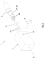
- connection system (1) comprises a male connection end (2), a female connection end (3) and a retaining element (4).
- the male connection end (2) is designed to be inserted into the female connection end (3) along an axial direction (X) to connect both ends (2, 3).
- the two connection ends (2, 3) are connected in shape coupling and are tightly assembled through the retaining element (4).
- the male connection end (2) comprises a retaining groove (21) which makes up a first recess (22).
- the male connection end (2) further comprises two circular slots (26), concentric to the axial direction (X), each one of them housing one sealing O-ring (27) to ensure the tightness of the connection system (1) when both ends (2, 3) are connected along said axial direction (X).
- the female connection end (3) comprises a retaining hole (31) which makes up a second recess (32) facing the first recess (22) when both ends (2, 3) are connected.
- the retaining element (4) is designed to be inserted through the retaining hole (31) and be housed between the first recess (22) and the second recess (32) to keep the male connection end (2) attached to the female connection end (3) when both ends (2, 3) are connected.
- connection system (1) comprises a gasket (5) formed by a rubber O-ring placed between the male connection end (2) and the female connection end (3), configured to hinder relative movements of said ends (2, 3) when connected along the axial direction (X).
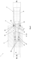
- Figure 3 shows a longitudinal section of the connection system (1) for fluid conduction of the present invention, according to a first preferred embodiment, when both connection ends (2, 3) are connected.
- the gasket (5) acts under compression in the junction between the male connection end (2) and the female connection end (3) at any operating situation, even if the pressure of the system is not maintained. In this way, the gasket (5) avoids the free play between the male connection end (2) and the female connection end (3), and at the same time seals the junction between both connection ends (2, 3) to prevent leakage.
- the hermeticity of the system is fully assured by providing sealing means interposed between the male connection end (2) and the female connection end, using the two O-rings (27).
- the gasket (5) also performs a sealing function, double safety is achieved for preventing leakage once both ends (2, 3) are connected.
- the gasket (5) is pressed between the male connection end (2) and the female connection end (3) when both ends (2, 3) are connected along the axial direction (X).
- the pressure of the gasket (5) can be adjusted by varying the dimensions and/or properties of the gasket (5) according to the operational needs. This adjustment must allow the introduction of the retaining element (4) through the retaining hole (31) for connecting the connection ends (2, 3), and to assure that, once the retaining element (4) is housed between the first recess (22) and the second recess (32), the gasket (5) remains under compression.
- the gasket (5) is partly disposed outside the female element (3) when both ends (2, 3) are connected along the axial direction (X).
- the male connection end (2) comprises an outer protruding wall (23) designed to press the gasket (5) against the female connection end (3).
- the male connection end (2) further comprises a boundary groove (24) designed to house the gasket (5), which is disposed between the male element (2) and the female element (3) when both ends (2, 3) are connected along the axial direction (X).
- the boundary groove (24) is located next to the outer protruding wall (23).
- the male connection end (2) further comprises a first cone wall (25) configured to receive a first portion of the gasket (5).
- the female element (3) further comprises a second cone wall (35) configured to receive a second portion of the gasket (5).
- the first cone wall (25) faces the second cone wall (35) when the male connection end (2) and the female connection end (3) are connected along the axial direction (X), forming a circular receiving groove (6) having a V-shaped cross section designed to receive the pressure exerted by the gasket (5).
- the V-shaped cross section is configured to partly lodge the gasket (5) and to transmit its pressure. So, when the gasket (5) is pushed by the outer protruding wall (23) against the internal angle that forms the circular receiving groove (6), it presses the cone walls (25, 35) in opposite direction. In this manner, a better and more homogeneous distribution of forces is obtained all along the circular receiving groove (6).
- the male connection end (2) comprises a front portion (2f) wherein the two circular slots (26) are disposed, having a front outer diameter ( ⁇ 2f ), and an intermediate portion (2i) wherein the retaining groove (21) is located, having an intermediated outer diameter ( ⁇ 2i ).
- the front outer diameter ( ⁇ 2f ) is smaller than the intermediated outer diameter ( ⁇ 2i ).
- Said double diameter avoids the two O-rings (27) to be cut during assembly of the connection. More specifically, if the front portion (2f) and intermediate portion (2i) had the same outer diameter ( ⁇ 2i , ⁇ 2f ), the O-rings (27) of the front portion (2f) could rub against the transversal edge of the second recess (32) of the female connection end (3) during the insertion of the male connection end (2) and be damaged.
- the male connection end (2) further comprises a rear portion (2r) having a rear outer diameter ( ⁇ 2r ).
- the rear outer diameter ( ⁇ 2r ) is larger than the intermediated outer diameter ( ⁇ 2i ), so that the outer protruding wall (23) can press the gasket (5) against the female connection end (3).
- Figures 4 and 5 show different views of the male connection end (2), according to a first preferred embodiment.
- the first recess (22) is formed by a first circular groove (22a) concentric to the axial direction (X).
- the first circular groove (22a) allows a relative rotational movement between the male connection end (2) and the female connection end (3) once attached. So, the male connection end (2) can be inserted within the female connection end (3) at any position.
- This first preferred embodiment is especially intended for connections in which the connection ends are aligned to one another, once connected, without any change of direction or orientation of the same being produced, such that the elements with which they are associated do not usually have a predetermined mounting position.
- Figures 6 - 8 show different views of the male connection end (2), according to a second preferred embodiment.
- the first recess (22) is formed by a first straight groove (22b).
- the first straight groove (22b) avoids a subsequent relative rotational movement between the male connection end (2) and the female connection end (3) once attached. So, a single insertion position of the male connection end (2) within a female connection (3) end can be fixed.
- This second preferred embodiment is especially intended for connections that only permit a single mounting position so as not to interfere with other components of the vehicle (such as the frame, chassis, fork, engine, handlebars, wheel, etc.).
- Such connections may be found for example in the automotive sector, and especially in the field of motorcycle brake systems, such as the wheel anti-lock braking systems (ABS).
- ABS wheel anti-lock braking systems
- Figures 9 and 10 show respectively a longitudinal section and a front view of the female connection end (3).
- the configuration of the female connection end (3) is the same for the two embodiments of the male connection end (2) previously described.
- the second recess (32) is formed by a second straight groove (32b), which in combination with the first circular groove (22a) allows the relative rotational movement between the male connection end (2) and the female connection end (3) once attached, and which in combination with the first straight groove (22b) prevents said rotational movement.
- the second straight groove (32b) also eases the manufacturing process as the second recess (32) may be formed by simply drilling the female connection end (3).
Landscapes
- Engineering & Computer Science (AREA)
- General Engineering & Computer Science (AREA)
- Mechanical Engineering (AREA)
- Quick-Acting Or Multi-Walled Pipe Joints (AREA)
Claims (13)
- Verbindungssystem zur Fluidleitung, umfassend ein männliches Verbindungsende (2), ein weibliches Verbindungsende (3) und ein Sicherungselement (4); wobei das männliche Verbindungsende (2) zwecks Verbindung der beiden Enden (2, 3) zum Einführen in Axialrichtung (X) in das weibliche Verbindungsende (3) ausgebildet ist; wobei das genannte männliche Verbindungsende (2) eine Aufnahmenut (21) unter Bildung einer ersten Ausnehmung (22) umfasst; und das genannte weibliche Verbindungsende (3) eine Aufnahmebohrung (31) unter Bildung einer zweiten Ausnehmung (32), die im verbundenen Zustand der beiden Enden (2, 3) der ersten Ausnehmung (22) gegenüberliegt, umfasst; und wobei das genannte Sicherungselement (4) zum Einführen durch die Aufnahmebohrung (31) und Einpassen zwischen der ersten Ausnehmung (22) und der zweiten Ausnehmung (32) ausgebildet ist, um im verbundenen Zustand der beiden Enden (2, 3) das männliche Verbindungsende (2) an dem weiblichen Verbindungsende (3) zu fixieren; wobei das genannte Verbindungssystem (1) eine zwischen dem männlichen Verbindungsende (2) und dem weiblichen Verbindungsende (3) angeordnete Dichtung (5) umfasst, die so ausgelegt ist, dass sie im verbundenen Zustand der genannten Enden (2, 3) in der genannten Axialrichtung (X) deren Bewegungen zueinander verhindert; dadurch gekennzeichnet, dass das männliche Verbindungsende (2) eine erste Konuswand (25) umfasst, die zur Aufnahme eines ersten Teils der Dichtung (5) ausgelegt ist; und dass das weibliche Verbindungsende (3) eine zweite Konuswand (35) umfasst, die zur Aufnahme eines zweiten Teils der Dichtung (5) ausgelegt ist; wobei im verbundenen Zustand des männlichen Verbindungsendes (2) mit dem weiblichen Verbindungsende (3) in Axialrichtung (X) die erste Konuswand (25) der zweiten Konuswand (35) gegenüberliegt, wodurch eine ringförmige Aufnahmenut (6) mit V-förmigem Querschnitt gebildet wird, die zur Aufnahme des von der Dichtung (5) ausgeübten Drucks dient.
- Verbindungssystem nach Anspruch 1, dadurch gekennzeichnet, dass im verbundenen Zustand der beiden Enden (2, 3) in Axialrichtung (X) die Dichtung (5) zwischen dem männlichen Verbindungsende (2) und dem weiblichen Verbindungsende (3) zusammengedrückt wird.
- Verbindungssystem nach einem der Ansprüche 1 bis 2, dadurch gekennzeichnet, dass im verbundenen Zustand der beiden Enden (2, 3) in Axialrichtung (X) ein Teil der Dichtung (5) außerhalb des weiblichen Anschlussendes (3) angeordnet ist.
- Verbindungssystem nach einem der Ansprüche 1 bis 3, dadurch gekennzeichnet, dass die Dichtung (5) aus einem Gummi-O-Ring besteht.
- Verbindungssystem nach einem der Ansprüche 1 bis 4, dadurch gekennzeichnet, dass die Dichtung (5) aus Ethylen-Propylen-Dien-Monomer-Kautschuk (EPDM) oder Fluorkautschuk (FKM) besteht.
- Verbindungssystem nach einem der Ansprüche 1 bis 5, dadurch gekennzeichnet, dass das männliche Verbindungsende (2) eine äußere vorstehende Wand (23) umfasst, die dazu dient, die Dichtung (5) an das weibliche Verbindungsende (3) anzudrücken.
- Verbindungssystem nach einem der Ansprüche 1 bis 6, dadurch gekennzeichnet, dass das männliche Verbindungsende (2) eine Begrenzungsnut (24) umfasst, die dazu dient, im verbundenen Zustand der beiden Enden (2, 3) in Axialrichtung (X) die zwischen dem männlichen Verbindungsende (2) und dem weiblichen Verbindungsende (3) angeordnete Dichtung (5) aufzunehmen.
- Verbindungssystem nach Anspruch 6 und 7, dadurch gekennzeichnet, dass die Begrenzungsnut (24) angrenzend an die äußere vorstehende Wand (23) angeordnet ist.
- Verbindungssystem nach einem der Ansprüche 1 bis 8, dadurch gekennzeichnet, dass die erste Ausnehmung (22) aus einer ersten ringförmigen Nut (22a) konzentrisch zur Axialrichtung (X) besteht.
- Verbindungssystem nach einem der Ansprüche 1 bis 8, dadurch gekennzeichnet, dass die erste Ausnehmung (22) aus einer ersten geraden Nut (22b) besteht.
- Verbindungssystem nach einem der Ansprüche 1 bis 10, dadurch gekennzeichnet, dass die zweite Ausnehmung (32) aus einer zweiten geraden Nut (32b) besteht.
- Verbindungssystem nach einem der Ansprüche 1 bis 11, dadurch gekennzeichnet, dass das männliche Verbindungsende (2) einen oder mehrere konzentrisch zur Axialrichtung (X) angeordnete ringförmige Schlitze (26) mit einem oder mehreren O-Ring-Dichtungen (27) umfasst, um im verbundenen Zustand der beiden Enden (2, 3) in der genannten Axialrichtung (X) die Dichtheit des Verbindungssystems (1) zu gewährleisten.
- Verbindungssystem nach einem der Ansprüche 1 bis 12, dadurch gekennzeichnet, dass es sich um ein hydraulisches System zur Fluidleitung in Fahrzeugen handelt.
Priority Applications (4)
| Application Number | Priority Date | Filing Date | Title |
|---|---|---|---|
| EP22194747.6A EP4336082B1 (de) | 2022-09-09 | 2022-09-09 | Verbindungssystem für fluidleitung |
| ES22194747T ES3041695T3 (en) | 2022-09-09 | 2022-09-09 | Connection system for fluid conduction |
| US18/462,853 US12188596B2 (en) | 2022-09-09 | 2023-09-07 | Connection system for fluid conduction |
| CN202311156957.0A CN117685436A (zh) | 2022-09-09 | 2023-09-08 | 用于流体传导的连接系统 |
Applications Claiming Priority (1)
| Application Number | Priority Date | Filing Date | Title |
|---|---|---|---|
| EP22194747.6A EP4336082B1 (de) | 2022-09-09 | 2022-09-09 | Verbindungssystem für fluidleitung |
Publications (3)
| Publication Number | Publication Date |
|---|---|
| EP4336082A1 EP4336082A1 (de) | 2024-03-13 |
| EP4336082C0 EP4336082C0 (de) | 2025-06-18 |
| EP4336082B1 true EP4336082B1 (de) | 2025-06-18 |
Family
ID=83271460
Family Applications (1)
| Application Number | Title | Priority Date | Filing Date |
|---|---|---|---|
| EP22194747.6A Active EP4336082B1 (de) | 2022-09-09 | 2022-09-09 | Verbindungssystem für fluidleitung |
Country Status (4)
| Country | Link |
|---|---|
| US (1) | US12188596B2 (de) |
| EP (1) | EP4336082B1 (de) |
| CN (1) | CN117685436A (de) |
| ES (1) | ES3041695T3 (de) |
Family Cites Families (8)
| Publication number | Priority date | Publication date | Assignee | Title |
|---|---|---|---|---|
| NO953921L (no) * | 1995-10-03 | 1997-04-04 | Raufoss Tech As | Kobling for trykkmedium |
| DE102006026263B3 (de) * | 2006-06-02 | 2007-07-19 | Uponor Innovation Ab | Zusammensteckbare Anschlussvorrichtung für Rohre |
| EP3104056A1 (de) | 2015-06-09 | 2016-12-14 | J.Juan S.A. | Steckverbinder für eine fluidleitung |
| US11346476B2 (en) * | 2016-04-18 | 2022-05-31 | Kerr Machine Co. | High pressure swivel joint |
| EP3862609A4 (de) * | 2018-10-05 | 2022-05-11 | J Juan, S.A. | Flüssigkeitskopplungssystem |
| TWI692594B (zh) * | 2019-06-21 | 2020-05-01 | 大瑞空壓機械有限公司 | 快接由令 |
| ES2927315T3 (es) * | 2019-07-23 | 2022-11-04 | J Juan S A U | Dispositivo de conexión para sistemas hidráulicos de vehículos, conector orientable y procedimiento de ensamblaje asociados al mismo |
| US11143348B2 (en) * | 2019-10-18 | 2021-10-12 | Greatness Sanitary Industrial Co. | Gas pipe joint |
-
2022
- 2022-09-09 ES ES22194747T patent/ES3041695T3/es active Active
- 2022-09-09 EP EP22194747.6A patent/EP4336082B1/de active Active
-
2023
- 2023-09-07 US US18/462,853 patent/US12188596B2/en active Active
- 2023-09-08 CN CN202311156957.0A patent/CN117685436A/zh active Pending
Also Published As
| Publication number | Publication date |
|---|---|
| US12188596B2 (en) | 2025-01-07 |
| EP4336082A1 (de) | 2024-03-13 |
| EP4336082C0 (de) | 2025-06-18 |
| US20240084938A1 (en) | 2024-03-14 |
| ES3041695T3 (en) | 2025-11-13 |
| CN117685436A (zh) | 2024-03-12 |
Similar Documents
| Publication | Publication Date | Title |
|---|---|---|
| US5533764A (en) | Transverse hydraulic coupling with lipped port | |
| KR101088199B1 (ko) | 고압력 적용가능 급속 커넥터 | |
| KR101504786B1 (ko) | 밸브 부품 | |
| EP0937935A1 (de) | Rohrverbindung | |
| GB2243659A (en) | Segmented pipe clamp with double load shoulders | |
| US4889369A (en) | Adapter fitting | |
| CN101578471B (zh) | 一种连接液压管路的快速连接器 | |
| CN101025240A (zh) | 改进型制动管连接器 | |
| EP3885623B1 (de) | Umkehrbarer bremsrohrverbinder | |
| EP4336082B1 (de) | Verbindungssystem für fluidleitung | |
| US11235745B2 (en) | Connection device for vehicle hydraulic systems, orientable connector and method of assembly associated therewith | |
| EP0667942B1 (de) | Kupplungsvorrichtung für gewindelose verbindungen | |
| EP1635105B1 (de) | Kupplungsvorrichtung für Rohr- und Schlauchverbindungen | |
| US4772051A (en) | Modular manifold brake hose end fitting | |
| EP3104056A1 (de) | Steckverbinder für eine fluidleitung | |
| US4488742A (en) | Connecting arrangement, especially for tubular elements | |
| CN112955688A (zh) | 流体耦接系统 | |
| EP4549797A1 (de) | Schnellkupplung für hydraulische systeme | |
| US10711876B1 (en) | Reinforcement sealing tubes for stabilizing a housing in an automobile transmission | |
| CN223178375U (zh) | 液压制动用的油管接头机构 | |
| US8402760B2 (en) | Vibration-decoupling device for hydraulics | |
| CN213452294U (zh) | 转向器油管连接结构 | |
| CN223622486U (zh) | 一种外扣式油管快接结构、油压碟刹系统及自行车 | |
| TW202134108A (zh) | 自行車煞車系統、自行車把手組件及自行車把手組件的轉接件 | |
| EP4081728B1 (de) | Hydraulikanordnung, insbesondere für bremsanlagen oder hydraulische betätigungsschaltungen von geräten im kraftfahrzeug- und motorradsektor |
Legal Events
| Date | Code | Title | Description |
|---|---|---|---|
| PUAI | Public reference made under article 153(3) epc to a published international application that has entered the european phase |
Free format text: ORIGINAL CODE: 0009012 |
|
| STAA | Information on the status of an ep patent application or granted ep patent |
Free format text: STATUS: THE APPLICATION HAS BEEN PUBLISHED |
|
| AK | Designated contracting states |
Kind code of ref document: A1 Designated state(s): AL AT BE BG CH CY CZ DE DK EE ES FI FR GB GR HR HU IE IS IT LI LT LU LV MC MK MT NL NO PL PT RO RS SE SI SK SM TR |
|
| STAA | Information on the status of an ep patent application or granted ep patent |
Free format text: STATUS: REQUEST FOR EXAMINATION WAS MADE |
|
| 17P | Request for examination filed |
Effective date: 20240731 |
|
| RBV | Designated contracting states (corrected) |
Designated state(s): AL AT BE BG CH CY CZ DE DK EE ES FI FR GB GR HR HU IE IS IT LI LT LU LV MC MK MT NL NO PL PT RO RS SE SI SK SM TR |
|
| GRAP | Despatch of communication of intention to grant a patent |
Free format text: ORIGINAL CODE: EPIDOSNIGR1 |
|
| STAA | Information on the status of an ep patent application or granted ep patent |
Free format text: STATUS: GRANT OF PATENT IS INTENDED |
|
| GRAS | Grant fee paid |
Free format text: ORIGINAL CODE: EPIDOSNIGR3 |
|
| GRAA | (expected) grant |
Free format text: ORIGINAL CODE: 0009210 |
|
| STAA | Information on the status of an ep patent application or granted ep patent |
Free format text: STATUS: THE PATENT HAS BEEN GRANTED |
|
| INTG | Intention to grant announced |
Effective date: 20250417 |
|
| AK | Designated contracting states |
Kind code of ref document: B1 Designated state(s): AL AT BE BG CH CY CZ DE DK EE ES FI FR GB GR HR HU IE IS IT LI LT LU LV MC MK MT NL NO PL PT RO RS SE SI SK SM TR |
|
| REG | Reference to a national code |
Ref country code: GB Ref legal event code: FG4D |
|
| REG | Reference to a national code |
Ref country code: CH Ref legal event code: EP |
|
| REG | Reference to a national code |
Ref country code: DE Ref legal event code: R096 Ref document number: 602022016011 Country of ref document: DE |
|
| REG | Reference to a national code |
Ref country code: CH Ref legal event code: EP |
|
| REG | Reference to a national code |
Ref country code: IE Ref legal event code: FG4D |
|
| U01 | Request for unitary effect filed |
Effective date: 20250702 |
|
| U07 | Unitary effect registered |
Designated state(s): AT BE BG DE DK EE FI FR IT LT LU LV MT NL PT RO SE SI Effective date: 20250709 |
|
| PG25 | Lapsed in a contracting state [announced via postgrant information from national office to epo] |
Ref country code: NO Free format text: LAPSE BECAUSE OF FAILURE TO SUBMIT A TRANSLATION OF THE DESCRIPTION OR TO PAY THE FEE WITHIN THE PRESCRIBED TIME-LIMIT Effective date: 20250918 Ref country code: GR Free format text: LAPSE BECAUSE OF FAILURE TO SUBMIT A TRANSLATION OF THE DESCRIPTION OR TO PAY THE FEE WITHIN THE PRESCRIBED TIME-LIMIT Effective date: 20250919 |
|
| U20 | Renewal fee for the european patent with unitary effect paid |
Year of fee payment: 4 Effective date: 20250909 |
|
| PG25 | Lapsed in a contracting state [announced via postgrant information from national office to epo] |
Ref country code: HR Free format text: LAPSE BECAUSE OF FAILURE TO SUBMIT A TRANSLATION OF THE DESCRIPTION OR TO PAY THE FEE WITHIN THE PRESCRIBED TIME-LIMIT Effective date: 20250618 |
|
| PG25 | Lapsed in a contracting state [announced via postgrant information from national office to epo] |
Ref country code: RS Free format text: LAPSE BECAUSE OF FAILURE TO SUBMIT A TRANSLATION OF THE DESCRIPTION OR TO PAY THE FEE WITHIN THE PRESCRIBED TIME-LIMIT Effective date: 20250918 |
|
| REG | Reference to a national code |
Ref country code: ES Ref legal event code: FG2A Ref document number: 3041695 Country of ref document: ES Kind code of ref document: T3 Effective date: 20251113 |
|
| PG25 | Lapsed in a contracting state [announced via postgrant information from national office to epo] |
Ref country code: IS Free format text: LAPSE BECAUSE OF FAILURE TO SUBMIT A TRANSLATION OF THE DESCRIPTION OR TO PAY THE FEE WITHIN THE PRESCRIBED TIME-LIMIT Effective date: 20251018 |
|
| PG25 | Lapsed in a contracting state [announced via postgrant information from national office to epo] |
Ref country code: SM Free format text: LAPSE BECAUSE OF FAILURE TO SUBMIT A TRANSLATION OF THE DESCRIPTION OR TO PAY THE FEE WITHIN THE PRESCRIBED TIME-LIMIT Effective date: 20250618 |
|
| PG25 | Lapsed in a contracting state [announced via postgrant information from national office to epo] |
Ref country code: CZ Free format text: LAPSE BECAUSE OF FAILURE TO SUBMIT A TRANSLATION OF THE DESCRIPTION OR TO PAY THE FEE WITHIN THE PRESCRIBED TIME-LIMIT Effective date: 20250618 |
|
| PG25 | Lapsed in a contracting state [announced via postgrant information from national office to epo] |
Ref country code: PL Free format text: LAPSE BECAUSE OF FAILURE TO SUBMIT A TRANSLATION OF THE DESCRIPTION OR TO PAY THE FEE WITHIN THE PRESCRIBED TIME-LIMIT Effective date: 20250618 |
|
| PG25 | Lapsed in a contracting state [announced via postgrant information from national office to epo] |
Ref country code: SK Free format text: LAPSE BECAUSE OF FAILURE TO SUBMIT A TRANSLATION OF THE DESCRIPTION OR TO PAY THE FEE WITHIN THE PRESCRIBED TIME-LIMIT Effective date: 20250618 |
|
| PGFP | Annual fee paid to national office [announced via postgrant information from national office to epo] |
Ref country code: ES Payment date: 20251003 Year of fee payment: 4 |
|
| PLBE | No opposition filed within time limit |
Free format text: ORIGINAL CODE: 0009261 |
|
| STAA | Information on the status of an ep patent application or granted ep patent |
Free format text: STATUS: NO OPPOSITION FILED WITHIN TIME LIMIT |
|
| REG | Reference to a national code |
Ref country code: CH Ref legal event code: H13 Free format text: ST27 STATUS EVENT CODE: U-0-0-H10-H13 (AS PROVIDED BY THE NATIONAL OFFICE) Effective date: 20260425 |
|
| REG | Reference to a national code |
Ref country code: CH Ref legal event code: L10 Free format text: ST27 STATUS EVENT CODE: U-0-0-L10-L00 (AS PROVIDED BY THE NATIONAL OFFICE) Effective date: 20260430 |