EP4336154A2 - Ladenwaage - Google Patents
Ladenwaage Download PDFInfo
- Publication number
- EP4336154A2 EP4336154A2 EP23000187.7A EP23000187A EP4336154A2 EP 4336154 A2 EP4336154 A2 EP 4336154A2 EP 23000187 A EP23000187 A EP 23000187A EP 4336154 A2 EP4336154 A2 EP 4336154A2
- Authority
- EP
- European Patent Office
- Prior art keywords
- state
- scales
- control unit
- led lamps
- state machine
- Prior art date
- Legal status (The legal status is an assumption and is not a legal conclusion. Google has not performed a legal analysis and makes no representation as to the accuracy of the status listed.)
- Granted
Links
Images


Classifications
-
- G—PHYSICS
- G01—MEASURING; TESTING
- G01G—WEIGHING
- G01G21/00—Details of weighing apparatus
- G01G21/22—Weigh pans or other weighing receptacles; Weighing platforms
-
- G—PHYSICS
- G01—MEASURING; TESTING
- G01G—WEIGHING
- G01G21/00—Details of weighing apparatus
- G01G21/28—Frames, Housings
-
- B—PERFORMING OPERATIONS; TRANSPORTING
- B41—PRINTING; LINING MACHINES; TYPEWRITERS; STAMPS
- B41J—TYPEWRITERS; SELECTIVE PRINTING MECHANISMS, i.e. MECHANISMS PRINTING OTHERWISE THAN FROM A FORME; CORRECTION OF TYPOGRAPHICAL ERRORS
- B41J11/00—Devices or arrangements of selective printing mechanisms, e.g. ink-jet printers or thermal printers, for supporting or handling copy material in sheet or web form
- B41J11/007—Conveyor belts or like feeding devices
-
- B—PERFORMING OPERATIONS; TRANSPORTING
- B41—PRINTING; LINING MACHINES; TYPEWRITERS; STAMPS
- B41J—TYPEWRITERS; SELECTIVE PRINTING MECHANISMS, i.e. MECHANISMS PRINTING OTHERWISE THAN FROM A FORME; CORRECTION OF TYPOGRAPHICAL ERRORS
- B41J11/00—Devices or arrangements of selective printing mechanisms, e.g. ink-jet printers or thermal printers, for supporting or handling copy material in sheet or web form
- B41J11/64—Applications of scales or indicators
-
- G—PHYSICS
- G01—MEASURING; TESTING
- G01G—WEIGHING
- G01G23/00—Auxiliary devices for weighing apparatus
-
- G—PHYSICS
- G01—MEASURING; TESTING
- G01G—WEIGHING
- G01G23/00—Auxiliary devices for weighing apparatus
- G01G23/005—Means for preventing overload
-
- G—PHYSICS
- G01—MEASURING; TESTING
- G01G—WEIGHING
- G01G23/00—Auxiliary devices for weighing apparatus
- G01G23/01—Testing or calibrating of weighing apparatus
- G01G23/012—Testing or calibrating of weighing apparatus with load cells comprising in-build calibration weights
-
- G—PHYSICS
- G01—MEASURING; TESTING
- G01G—WEIGHING
- G01G23/00—Auxiliary devices for weighing apparatus
- G01G23/18—Indicating devices, e.g. for remote indication; Recording devices; Scales, e.g. graduated
- G01G23/38—Recording and/or coding devices specially adapted for weighing apparatus
- G01G23/42—Recording and/or coding devices specially adapted for weighing apparatus electrically operated
-
- H—ELECTRICITY
- H05—ELECTRIC TECHNIQUES NOT OTHERWISE PROVIDED FOR
- H05B—ELECTRIC HEATING; ELECTRIC LIGHT SOURCES NOT OTHERWISE PROVIDED FOR; CIRCUIT ARRANGEMENTS FOR ELECTRIC LIGHT SOURCES, IN GENERAL
- H05B45/00—Circuit arrangements for operating light-emitting diodes [LED]
- H05B45/30—Driver circuits
- H05B45/32—Pulse-control circuits
- H05B45/335—Pulse-frequency modulation [PFM]
-
- H—ELECTRICITY
- H10—SEMICONDUCTOR DEVICES; ELECTRIC SOLID-STATE DEVICES NOT OTHERWISE PROVIDED FOR
- H10H—INORGANIC LIGHT-EMITTING SEMICONDUCTOR DEVICES HAVING POTENTIAL BARRIERS
- H10H29/00—Integrated devices, or assemblies of multiple devices, comprising at least one light-emitting semiconductor element covered by group H10H20/00
- H10H29/10—Integrated devices comprising at least one light-emitting semiconductor component covered by group H10H20/00
- H10H29/14—Integrated devices comprising at least one light-emitting semiconductor component covered by group H10H20/00 comprising multiple light-emitting semiconductor components
-
- B—PERFORMING OPERATIONS; TRANSPORTING
- B41—PRINTING; LINING MACHINES; TYPEWRITERS; STAMPS
- B41J—TYPEWRITERS; SELECTIVE PRINTING MECHANISMS, i.e. MECHANISMS PRINTING OTHERWISE THAN FROM A FORME; CORRECTION OF TYPOGRAPHICAL ERRORS
- B41J2203/00—Embodiments of or processes related to the control of the printing process
- B41J2203/01—Inspecting a printed medium or a medium to be printed using a sensing device
- B41J2203/011—Inspecting the shape or condition, e.g. wrinkled or warped, of a medium to be printed before printing on it
Definitions
- the present invention relates to a scale, in particular a shop scale, with a weighing module.
- the weighing module includes a housing in which a load cell is housed.
- the load cell includes a fixed section, a deformation section and a movable section.
- the fixed section is connected to the housing and the movable section carries a load cross with a load plate.
- the deformation section has a strain gauge for measuring a weight acting on the load plate.
- the DE 20 2011 050 040 U1 shows a household scale whose load plate is equipped with a writing surface that can be written on with a pen.
- the writing surface is translucent and illuminated from behind.
- the DE 10 2011 083 562 A1 shows a personal scale that includes a light source that is arranged below the load plate and illuminates the lower area of the scale.
- the DE 10 2009 049 567 A1 shows a bathroom scale with a display device that provides feedback to a person being weighed as to whether they are standing correctly on the load plate.
- Shop scales Scales are well known to those skilled in the art. These scales usually include an operator display for interacting with the scale, for example to display a weight or to indicate malfunctions. The operator has to navigate through different menu levels to obtain specific information about the status of the scale. This is often complex and not very intuitive for the operator.
- the object of the invention is to create a simple device that informs the operator about the technical condition of the Libra informs him and makes it easier for him to interact with the scale.
- a scale in particular a shop scale, is proposed.
- the scale includes a weighing module.
- the weighing module includes a housing in which a load cell is housed.
- the load cell includes a fixed section, a deformation section and a movable section.
- the fixed section is connected to the housing.
- the movable section carries a load cross with a load plate.
- the deformation section has a strain gauge for measuring a weight acting on the load plate.
- a light strip is attached essentially all the way around the housing. Essentially circumferential in this context means that the light strip runs around three sides and a large part of the fourth side of the housing, but that the beginning and the end of the light strip do not have to be connected or meet.
- the scale includes a control unit with a state machine that represents at least one technical state of the scale, wherein the control unit controls the light band based on the state of the state machine.
- the light strip includes first, second and third LED lamps.
- the first LED lamps produce light in a wavelength range of 450°nm to 500°nm, which corresponds to the color blue.
- the second LED lamps produce light in a wavelength range of 500°nm to 570°nm, which corresponds to the color green.
- the third LED lamps produce light in a wavelength range of 610°nm to 760°nm, which corresponds to the color red.
- the light strip consists of a flexible carrier. On the flexible The LED lamps are arranged on the carrier.
- the carrier comprises one to ten LED lamps per cm of length.
- the first, second and third LED lamps are arranged in regular arrangements on the carrier.
- the first LED lamps form a first group of LED lamps.
- the second LED lamps form a second group of LED lamps.
- the third LED bulbs form a third group of LED bulbs.
- the LED lamps in a group are controlled together by the control unit.
- the control unit permanently supplies a third group of LED lamps of the light strip with a voltage when the state machine is in a first state.
- the control unit permanently supplies a second group of LED lamps of the light strip with a voltage when the state machine is in a second state.
- the light strip is covered with silicone on the side on which the LED lamps are attached. Silicone is translucent. At the same time, a diffuse effect is created so that the light from the individual LED lamps is scattered slightly. This creates superimposed colors from the three groups of LED lamps, which are visible to the human eye as blue, green and red, so that almost the entire RGB color space is available.
- the human eye thus perceives the light strip as glowing red when the state machine is in a first state and the third group of LED lamps is supplied with voltage by the control device.
- the human eye perceives the light strip as glowing green when the state machine is in the second state and the second group of LED lamps is supplied with voltage by the control device.
- the technical state represented by the state machine is a paper supply in a printer.
- the technical state that is represented by the state machine is a difference to a target weight, which is formed by the weight determined by the load cell and the target weight.
- the technical state that is represented by the state machine is an outdated software version that needs to be updated through updates.
- the technical state that is represented by the state machine is a speed of various weight detection steps or processing steps entered via an operator display.
- the technical state that is represented by the state machine is that an operator has correctly identified himself at the scale via the operator display.
- the housing is designed in one piece and is trough-shaped.
- the person skilled in the art understands a one-piece, trough-shaped housing to be a shape of a housing that resembles a trough. It has a square or rectangular base, although the corners can be rounded.
- the housing has a base body, which in one embodiment is made from a cast metal and can therefore also have complex shapes, in particular openings and inner walls. The length and width of the housing are significantly larger than its height.
- the housing includes a base plate with side walls that are integrally formed on the base plate. The case is open at the top and with a clearance inside to accommodate different modules such as the load cell, electronic modules and others inside the case.
- the interior of the housing is covered at the top with a cover.
- the term one-piece and trough-shaped also includes a housing that has partitions inside for various purposes Has spaces or stabilization struts. Furthermore, this also includes a housing whose base plate is stepped-shaped in some places, so that a free space is created at these points of the housing below the base plate of the housing when the base body is placed on a flat surface. This free space is used, for example, for attaching plugs underneath the housing.
- the housing is also to be understood as being in one piece and trough-shaped if there are through openings at various points in the, in particular stepped, base plate or side walls, for example for attaching plug sockets, passing cables through or installing supports and other elements the scales.
- the term trough-shaped is therefore only to be seen as descriptive of the basic appearance of the housing.
- the state machine is a finite automaton that consists of states, state transitions and actions.
- the control unit comprises a memory in which a target weight is stored.
- the state machine is in the second state when the weight value measured by the load cell corresponds to the target weight.
- the state machine is in the first state when the weight value measured by the load cell deviates from the target weight.
- the target weight should not be understood as a discrete weight specification. Rather, the target weight is a weight range, that is, a discrete weight specification with a certain tolerance, for example 5% or 10%.
- the target weight when using the scale in the food sector is 190 g - 210 g. If the weight value measured by the load cell is in this band, then it corresponds to the target weight and the state machine is in a second state.
- the weight value measured by the load cell is outside this band, for example at 180 g, then the weight value measured by the load cell deviates Target weight and the state machine is in the first state.
- the person skilled in the art therefore understands the expression target weight as an indication of a weight range, the width of the weight range being small in comparison to the absolute weight value.
- the operator can interact with the scale when he is informed via the light strip whether he needs to place additional products, for example slices of food, on the scale's load plate in order to achieve a target weight, or that the scale
- the light strip signals that the target weight has been reached.
- the scale thus guides the operator's interaction with the scale.
- a target number of pieces and an average weight per piece are stored in a memory in the control unit.
- the control unit determines a target weight by multiplying the target number of pieces by the average weight per piece.
- the weight value measured by the load cell is then compared with the target weight. If a number of objects with the specific weight corresponding to the target number is placed on the scale, the target weight is reached and measured by the load cell. In this case, the state machine is in the second state. If there are more or fewer pieces than the target number of a product with a corresponding weight on the scales, the correspondingly calculated target weight is exceeded or fallen short of.
- the weight value measured by the load cell deviates from the target weight so that the state machine is in the first state.
- the light strip is controlled accordingly by the control unit.
- the scale signals to the user whether a desired number of products has been counted.
- the operator can interact with the scale when he is informed via the light strip whether he needs to place additional products, for example piece goods, on the load plate of the scale in order to achieve a target number of pieces, or that the scale
- the light strip signals that the target quantity has been reached.
- the scale thus guides the operator's interaction with the scale.
- the target weight as well as the number of pieces and the specific weight of a product to be weighed are entered by the operator via a computer unit on the scale.
- the computer unit for example, is an all-in-one PC that also serves as a touchscreen to operate the scale. However, it is irrelevant to the invention how this data is made available to the control unit.
- the scale includes a printer.
- the printer unrolls paper, in particular direct thermal paper, from an endless roll using a motor-driven printing roller and feeds it to a print head for direct thermal printing.
- the printer includes a sensor that determines the length of paper used.
- the control of the pressure roller determines the length of the paper used, since the number of revolutions of the pressure roller can be determined in the control and the diameter of the pressure roller is a known parameter.
- the control unit determines the difference between the paper length originally present on the endless roll minus the length of the paper used since the last paper roll change. This corresponds to the paper supply still remaining on the continuous roll.
- the state machine remains in the second state as long as the difference is greater than a threshold value.
- the state machine switches to the first state when the difference falls below a threshold value. This threshold indicates that the paper supply on the continuous roll is depleted or close to depleted and the operator should insert a new paper roll. The state machine is then in the first state.
- control unit comprises a receiver designed to receive data from a computer unit.
- the state machine of the control unit transitions from the second state to the first state when the receiver receives a signal from the computer unit indicating the need for a software update.
- the control unit comprises a receiver designed to receive data from a computer unit.
- the state machine of the control unit changes from the second state to the first state when the receiver receives a signal from the computer unit that an operator has registered with his operator ID on the computer unit for operator sales.
- the state machine of the control unit changes from the first state to the second state when the receiver receives a signal from the computer unit that an operator has logged out of the computer unit with his operator ID.
- the computer unit for example, is an all-in-one PC that also serves as a touchscreen to operate the scale. However, it is irrelevant to the invention how this data is made available to the control unit.
- the state machine of the control unit changes from the second state to the first state when the weight value measured by the load cell represents an overload of the load cell. The operator can then immediately remove the product from the load plate to avoid possible damage to the scale and especially the load cell.
- the state machine of the control unit is in the second state when the load cell carries out a number of weighing processes per unit of time that is above a threshold value stored in the control unit.
- the state machine of the control unit is in a first state when the load cell carries out a number of weighing operations per unit of time that is below the threshold value.
- the State machine thus monitors the speed at which an operator interacts with the scale, in particular how many weighing operations an operator carries out per unit of time.
- a weighing process is recognized, for example, when the load cell records a weight value and then the weight value returns to zero or to the preload of the load plate and load cross.
- the state machine is in a first state when the weight value measured by the load cell deviates downwards from the target weight.
- the state machine is in a third state when the weight value measured by the load cell deviates upward from the target weight.
- the state machine is in a second state when the weight value measured by the load cell corresponds to the target weight.
- the light strip includes at least second and third LED lamps.
- the second LED lamps produce light in the wavelength range from 500°nm to 570°nm. This corresponds to green light.
- the third LED lamps produce light in the wavelength range from 610°nm to 760°nm. This corresponds to red light.
- the second and third LED lamps are arranged in regular arrangements on the light strip.
- the second and third LED lamps are each controlled together as a group by the control unit and supplied with voltage. This means that all second LED lamps are switched on or off together. Likewise, all third LED lamps are switched on or off together. However, this does not exclude the possibility that the second LED lamps and the third LED lamps and/or further groups of LED lamps are controlled together and switched on or off.
- the control unit permanently applies voltage to the second LED lamps of the light strip when the state machine is in a second state.
- the control unit acts on the second and the third LED lamps of the light strip are permanently energized when the state machine is in a first state. The green and red LED lights are on at the same time.
- the regular arrangement of the second LED lamps and the third LED lamps and the superposition of the light from the second LED lamps and the third LED lamps results in yellow light through additive color mixing.
- the control unit permanently applies voltage to the third LED lamps of the light strip when the state machine is in a third state.
- the light band lights up red. This means that the light band lights up yellow when the target weight is undershot.
- the light band lights up red when the target weight is exceeded.
- the scales enable the operator to have a guided human-machine interaction in that the operator can place additional products, for example sausage slices, on the load plate due to the activation of the light strip by the control unit and the resulting yellow or red glow of the light strip , for example sausage slices, can be removed from the load plate until the difference value that is formed in the control unit between the target weight and the measured weight value falls below a threshold value and the target weight is therefore considered to have been reached.
- This causes the control unit to switch to an operating mode in which only the second lamps are supplied with a voltage by the control unit.
- the light band then lights up green.
- a target weight is calculated in the control unit based on the specific weight of a screw and the scale enables the operator to have a guided human-machine interaction in order to select a quantity from a number of pieces of goods Example 100 screws to form on the load plate.
- the light strip runs around the housing once, in particular the light strip runs around the housing once in the upper region of its side walls, whereby there can be a small distance between the beginning and end of the light strip in relation to the length of the light strip.
- the scale includes a load plate that is placed on the load cross. The outer edges of the load plate lead over the load cross and down over the upper edge of the housing so that the load plate floats on the top of the housing like a lid.
- the light strip is located in the upper region of the side walls of the housing, but below the edges of the load plate.
- the light strip is attached to the upper edge of the housing in such a way that it is covered by the protruding edges of the load plate. In this case, the light from the light strip shines diffusely under the downward edges of the load plate.
- electrical lines for controlling the LED lamps are integrated into the flexible carrier material of the light strip.
- the flexible carrier has a layer of adhesive material on the side opposite the LED lamps. In one embodiment it is a layer of thermally conductive adhesive material.
- the light strip is attached to the housing with the adhesive material, in particular glued.
- the heat generated by the LED lamps is transferred to the housing via the layer of adhesive material, in particular via the heat-conducting adhesive material.
- the adhesive material adheres to a surface made of uncoated and/or coated cast metal, so that the housing can be coated or uncoated at the point where the light strip is glued.
- the light strip is electrically connected to the control unit.
- the light strip is supplied by the control unit with a DC voltage in the range of 6°Volt to 36°Volt, especially 12°Volt or 24°Volt, controlled.
- the housing comprises a recess or a one-sided recess, which is attached all around in the upper housing area on the outside of the housing, into which the light strip is glued.
- recess is understood to mean a recess in the housing wall in the form of a groove.
- a one-sided recess means an edge that is present, for example, in a sloping housing wall. The edge forms a depression, the rear end of which is a vertical plane to accommodate the light strip.
- the scale includes a diffuser that is attached to the outside of the housing and covers the recess.
- the diffuser ensures that the light from the LED lamps is dispersed, so that it can no longer be seen that they are discrete light sources, but rather that the impression is created that they are an extensive, homogeneous lamp.
- the diffuser also ensures that the light strip appears equally bright from every viewing angle. The diffuser enhances the effect of the silicone.
- the diffuser is made of a translucent material.
- the translucent material is a translucent polycarbonate.
- the diffuser includes structuring on its outside.
- the structuring makes the diffuser opaque from the outside towards the housing.
- the diffuser is translucent from the side of the housing to the outside.
- the diffuser is designed as a ring.
- the ring has the dimensions of the housing in the area of the recess.
- the ring is positively attached to the housing above the recess.
- the Ring attached with a locking mechanism.
- the diffuser covers the recess.
- the diffuser is glued or screwed to the housing.
- the distance between the LED lamps and the inside of the diffuser is less than 3°mm. In one embodiment, the distance between the LED lamps and the inside of the diffuser is less than 1°mm.
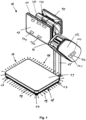
- Fig. 1 shows a scale 10 according to the invention according to a first embodiment.
- the scale includes a weighing module with a housing 18 in which a load cell is accommodated.
- the load cell carries a load cross, which in turn carries a load plate 11.
- the load plate 11 has a downward edge which protrudes over the upper edge of the housing 18.
- a tripod 15 is attached to the weighing module and carries a printer 12 with a label output 16.
- the printer 12 has a transmitter 121 which transmits the length of the paper a full paper roll.
- the printer 12 has a transmitter 123 which transmits the current paper consumption, which is determined by the rotation of a printing roller.
- the printer 12 has a transmitter 122 that sends a reset signal when a new roll of paper is inserted into the printer 12.
- the stand 15 also carries an operator display 13, which is designed as a touchscreen, and a customer display 14 opposite the operator display 13.
- the operator display 13 is an all-in-one PC and includes a computer unit that contains the computer-implemented functions 131 or operator inputs 130 , 132, 133, 134 of the scale ensures.
- the weighing module rests on four feet 17 attached to its corners.
- a light strip 19 is attached all around the outer edge of the housing 18, which is controlled by a control unit depending on the technical condition of the scale.
- Fig. 2 shows a scale 20 according to the invention according to a second embodiment.
- the scale includes a weighing module with a housing 28 in which a load cell is accommodated.
- the load cell carries a load cross, which in turn carries a load plate 21.
- the load plate 21 has a downward edge which protrudes over the upper edge of the housing 28.
- the weighing module rests on a frame 25 which carries a printer 22 with a label output 26.
- the printer 22 has a transmitter 221 which transmits the length of paper that is on a full roll of paper.
- the printer 22 has a transmitter 223 which transmits the current paper consumption, which is determined by the rotation of a printing roller.
- the printer 22 has a transmitter 222 that sends a reset signal when a new roll of paper is inserted into the printer 22. is inserted.
- the frame 25 also carries an operator display 23, which is designed as a touchscreen, and a customer display 24 opposite the operator display 23.
- the operator display 23 is an all-in-one PC and includes a computer unit that contains the computer-implemented functions 230 or operator inputs 230 , 232, 233, 234 of Libra ensures.
- a light strip 29 is attached all around the outer edge of the housing 28 and is controlled by a control unit depending on the technical condition of the scale.
- Fig. 3 shows a section through the housing 18, 28 of a balance 10, 20.
- the housing 18, 28 is a cast metal housing and can take on complex shapes.
- a load cell 30 is screwed to a base 35 with screws 34.
- the load cell 30 comprises a fixed section 31 screwed to the housing 18, 28, a deformation section 32 and a movable section 33, on which a load cross 39 with a fastening 38 is attached.
- the load cross 39 carries the load plate 11, 21 of the scale, with rubber buffers 40 being attached between the load cross 39 and the load plate 11, 21.
- the load plate 11, 21 includes a bend 50 on its edges, so that the load plate 11, 21 projects laterally downward over the upper edges of the housing 18, 28.
- the interior of the housing 18, 28, in which the weighing cell 30 and also a control unit 51 and possibly other components of the scale such as a power supply and the like are located, is covered with a cover 41.
- the housing 18, 28 consists of a base plate and four upwardly projecting side walls.
- the housing is made of cast metal and is therefore made in one piece.
- the transition between the base plate and side walls is slanted.
- a recess 44 is made in the upper area of the side walls, so that a vertical outer wall 47 is set back somewhat on the side walls of the housing 18, 28.
- the carrier 42 of the light strip 19, 29 is glued to the vertical outer wall 47.
- the carrier 42 is made of flexible material and can therefore also be guided around the corners of the housing 18, 28 in the recess 44.
- flexible means that the carrier 42 can be bent at least perpendicular to the plane in which the carrier 42 runs, but not necessarily also in the plane of the carrier 42 itself.
- LED lamps 43 are placed on the carrier 42.
- the LED lamps 43 can be attached in the longitudinal direction of the carrier 42 with a density of up to ten LED lamps 43 per cm.
- Carrier 42 and LED lamps 43 are covered with a protective layer 48 made of silicone on the side of the LED lamps.
- the protective layer 48 is not only applied to the LED lamps 43 themselves before they are mounted on the carrier 42, but is attached over the carrier 42 and the LED lamps 42 after the LED lamps 43 have been mounted on the carrier 42. In this way, a higher density of the LED lamps 43 can be achieved on the carrier 42 and the beam angle for homogeneous light of each LED lamp 43 increases to approximately 170 °.
- a protective layer 48 made of silicone is applied when the LED lamps 43 generate light in the wavelength range from 450 ° nm to 500 ° nm, 500 ° nm to 570 ° nm or 610 ° nm to 760 ° nm and the different LED lamps 43 in regular arrangements on the carrier 42 are arranged.
- the light strip 19, 29 can be made to light up in RGB colors via the control unit 51.
- the recess 44 with carrier 42, LED lamps 43 and protective layer 48 is covered by a diffuser 49.
- the diffuser 49 offers mechanical protection for the light strip 19, 29 and refracts the light at the same time, so that the light strip 19, 29 acts like a homogeneous light source.
- the diffuser 49 can be structured on its outer surface, that is, surface-processed.
- the effect that the light strip 19, 29 acts like a homogeneous light source is due to the high density of LED lamps 43 and the common protective layer 48 made of silicone on the LED lamps 43 and reinforced or completed by the diffuser 49 and the external structuring of the diffuser 49.
- the diffuser 49 rests on surfaces 45, 46 of the housing 18, 28 above and below the recess 44 and is glued to these surfaces 45, 46, locked or screwed to them with a latching connection.
- the diffuser 49 is an annular component that is pushed over the housing 18, 28 from below and fits positively onto the side walls of the housing 18, 28.
- the diffuser 49 is made of translucent material, in particular translucent polycarbonate.
- the control unit 51 includes a state machine 52, which represents at least one technical state of the scale.
- the control unit controls the light strip 19, 29 based on the state of the state machine 52.
- the technical state that is represented by the state machine can be a paper supply in a printer, a difference to a target weight that is formed by the weight determined by the load cell and the target weight, an outdated software version that needs to be updated through updates, a speed of various weight recording steps or processing steps entered via an operator display or that an operator has correctly identified themselves on the scale via the operator display.
- the light strip can be controlled, for example, in different colors (red, yellow, green) for an RGB light strip or as glowing or flashing a monochrome light tape.
- Fig. 4 shows a schematic representation of the control unit 51 and the state machine 52 implemented in the control unit Fig. 4 different state machines 52a, 52b, 52c, 52d, 52e, 52f, 52g, all or only some of which can be implemented in a control unit 51 of a scale 10, 20 according to the invention.
- Each state machine 52a, 52b, 52c, 52d, 52e, 52f, 52g is assigned a control module 51a, 51b, 51c, 51d, 51e, 51f, which interacts with the corresponding state machine 52a, 52b, 52c, 52d, 52e, 52f, 52g and part of the control unit 51.
- the first control module 51a receives a target weight 130, 230 from an input device of the scales 10, 20, for example the operator display 13, 23. Alternatively, the first control module 51a receives a target number of pieces 134, 234 from an input device 13, 23 of the scales 10, 20 of products and a specific gravity 133, 233 per product. The first control module 51a calculates a target weight from the target number of pieces 134, 234 and the specific weight 133, 233 per product. The first control module 51a can determine a weight range from the target weight that includes tolerances, in which case the entire weight range is then viewed as the target weight. Furthermore, the first control module 51a receives weight values determined by the weighing cell 30.
- the first state machine 52a switches or remains in a second state 52a2. If the weight determined by the load cell 30 does not correspond to the target weight, the first state machine 52a switches or remains in the first state 52a1.
- the state transitions between the first state 52a1 and the second state 52a2 are indicated in the drawing, although remaining in the corresponding state is not indicated separately for reasons of clarity.
- the second control module 51b receives from a printer 12, 22 a length of paper 121, 221, which is present on an endless roll of direct thermal paper, and a reset signal 122, 222, which states that a full direct thermal roll has been newly inserted into the printer.
- the second control module 51b continuously receives information 123 from the printer 12, 22, 223, how much paper is fed to the print head via the motor-driven printing roller. This corresponds to the direct thermal paper used.
- the second control module 51b forms the difference between the paper length 121, 221 on the endless roll and the used paper 123, 223. If this difference is smaller than a threshold value, in particular zero, that is, the paper supply of the label roll has been used up, the second control module 51b switches the second state machine 52b into the first state 52b1.
- the second state machine 52b remains in the second state 52b2. If a paper roll is filled and the second control module 51b receives a corresponding reset signal 122, 222 from the printer 12, 22, the second control module 51b moves the second state machine 52b to the second state 52b2.
- the third control module 51c receives a request 131 to update 231 updates for the software from a computer unit of the scale 10, 20, which is integrated, for example, in the operator display 13, 23 of the scale as an all-in-on computer.
- the third control module 51c causes the third state machine 52c to transition to the first state 52c1. If the third control module 51c receives from the scales 10, 20 that the updates have been installed, the third control module 51c causes the third state machine 52c to transition to the second state 52c2.
- the fourth control module 51d receives information 132, 232 from a computer unit of the scale 10, 20, which is integrated, for example, in the operator display 13, 23 of the scale as an all-in-on computer, information 132, 232 as to whether an operator is currently registered for operator sales at the scale is. If an operator has logged in, the fourth control module 51d causes the fourth state machine 52d to transition to the first state 52d1. The fourth control module 51d receives the information 132, 232 from the scales 10, 20 that the operator has completed the operating process and thus the scales again is free for further operators, the fourth control module 51d causes the fourth state machine 52d to transition to the second state 52d2.
- the load cell 30 If the load cell 30 is loaded with objects during operation that exceed the maximum permissible weight of the load cell 30, this represents an overload situation. In this case, the load cell 30 issues a corresponding warning signal.
- the fifth control module 51e receives a warning signal from the load cell 30 that represents an overload situation and causes the fifth state machine 52e to transition to the first state 52e1. If the fifth control module 51e no longer receives an overload signal from the load cell 30, the fifth control module 51e causes the fifth state machine 52e to transition to the second state 52d2.
- the sixth control module 51f receives a threshold value 135, 235 from a computer unit of the scale 10, 20, which is integrated, for example, in the operator display 13, 23 of the scale as an all-in-on computer, a threshold value 135, 235, indicating how many weighings an operator must carry out per unit of time. In addition, the sixth control module 51f continuously receives the weighings from the weighing cell 30. The sixth control module calculates from this whether the necessary number of weighings per unit of time has been achieved by the operator. The sixth control module 51f moves the sixth state machine 52f to the first state 52f1 if the threshold value 135, 235 is not reached. The sixth control module 51f moves the sixth state machine 52f to the second state 52f2 if the threshold value 135, 235 is reached or exceeded.
- the seventh control module receives a target weight from an input device of the scales 10, 20, for example the operator display 13, 23. Alternatively, the seventh control module receives a target number of products and a specific weight per product from an input device 13, 23 of the scales 10, 20. The seventh control module calculates a target weight from the target number of units and the specific weight per product.
- the seventh control module can determine a weight range from the target weight that includes tolerances, with the entire weight range then being viewed as the target weight.
- the seventh control module as well as the data received from the seventh control module such as target weight, target number of pieces or specific weight per product are in Fig. 4 not shown for reasons of clarity.
- a representation would be analogous to the representation of the first control module 51a.
- the seventh control module receives weight values determined by the weighing cell 30. If a weight value determined by the weighing cell 30 corresponds to the target weight, the seventh state machine 52g switches or remains in a second state 52g2. If the weight determined by the weighing cell 30 falls below the target weight, the seventh state machine 52g switches or remains in the first state 52g1. If the weight determined by the load cell 30 exceeds the target weight, the seventh state machine 52g switches or remains in the third state 52g3.
- the control device 51 includes controllers 53, 54, which control the light strip 19, 29 and supply it with voltage. A selection must be made in advance as to which of the state machines 52a, 52b, 52c, 52d, 52e, 52f supplies the controller with an input signal at a time and which controller 53, 54 controls the light strip 19, 29.
- the light band 19, 29 can only reflect the state of a state machine at a time. This selection must be made by the operator in the operator display 13, 23.
- the first to sixth state machines 52a, 52b, 52c, 52d, 52e, 52f are connected to the first controller 53.
- the seventh state machine is connected to the second controller 54.
- the light strip 19, 29 is a light strip 19, 29 with lamps 43 in the wavelength range from 230 nm to 500 nm (monochrome light strip)
- the light strip 19, 29 flashes.
- the light strip is subjected to a permanent voltage by the controller 53b.
- the second controller 54 controls the light strip 19, 29 and the seventh state machine is in a first state 52g1
- the light strip is supplied with a pulsed voltage of a first frequency by the controller 54a.
- the light strip 19, 29 flashes slowly.
- the seventh state machine is in a third state 52g3, the light strip is supplied with a pulsed voltage of a second frequency by the controller 54c.
- the light strip 19, 29 flashes quickly.
- the seventh state machine 52g is in a second state 52g2
- the light strip is subjected to a permanent voltage by the controller 54b.
- the light strip 19, 29 lights up.
- the light strip 19, 29 is a light strip 19, 29 with a group of second LED lamps 43 with a wavelength range of 500 ° nm to 570 ° nm (green light) and a group of third LED lamps 43 with a If the wavelength range is 610°nm to 760°nm (red light), the following applies: If the first controller 53 controls the light strip 19, 29 and the selected state machine 52a, 52b, 52c, 52d, 52e, 52f is in a first state 52a1, 52b1, 52c1, 52d1, 52e1, 52f1, the group becomes third LED lamps 43 of the light strip are supplied with a permanent voltage by the controller 53a. The light strip 19, 29 lights up red.
- the group of second LED lamps 43 of the light strip is controlled by the controller 53b subjected to permanent tension.
- the second controller 54 controls the light strip 19, 29 and the seventh state machine is in a first state 52f1
- the group of second LED lamps 43 and the group of third LED lamps 43 of the light strip are connected by the controller 54a with one permanent voltage applied.
- the light strip 19, 29 lights up yellow.
- the seventh state machine is in a third state 52f3, the group of third LED lamps 43 of the light strip is supplied with a permanent voltage by the controller 54c.
- the light strip 19, 29 lights up red.
- the seventh state machine 52f is in a second state 52f2
- the group of second LED lamps 43 of the light strip is supplied with a permanent voltage by the controller 53b.
- the light strip 19, 29 lights up green.
- DSP digital signal processor
- ASIC application specific integrated circuit
- FPGA field programmable gate array
- ROM read only memory
- RAM random access memory
- non-volatile memory is provided.
Landscapes
- Physics & Mathematics (AREA)
- General Physics & Mathematics (AREA)
- Cash Registers Or Receiving Machines (AREA)
Abstract
Description
- Die vorliegende Erfindung betrifft eine Waage, insbesondere eine Ladenwaage, mit einem Wägemodul. Das Wägemodul umfasst ein Gehäuse, in dem eine Wägezelle untergebracht ist. Die Wägezelle umfasst einen festen Abschnitt, einen Verformungsabschnitt und einen beweglichen Abschnitt. Der feste Abschnitt ist mit dem Gehäuse verbunden und der bewegliche Abschnitt trägt ein Lastkreuz mit einer Lastplatte. Der Verformungsabschnitt weist einen Dehnungsmesstreifen zur Messung eines auf die Lastplatte wirkenden Gewichts auf.
- Die
DE 20 2011 050 040 U1 zeigt eine Haushaltswaage, deren Lastplatte mit einer Schreibfläche ausgestattet ist, die mit einem Stift beschriftet werden kann. Dabei ist die Schreibfläche transluzent ausgeführt von hinten und beleuchtet. - Die
DE 10 2011 083 562 A1 zeigt eine Personenwaage, die eine Lichtquelle umfasst, die unterhalb der Lastplatte angeordnet ist und den unteren Bereich der Waage ausleuchtet. - Die
DE 10 2009 049 567 A1 zeigt eine Personenwaage mit einer Anzeigevorrichtung, die einer zu wiegenden Person Rückmeldung darüber gibt, ob sie korrekt auf der Lastplatte steht. - Ladenwaagen Waagen sind dem Fachmann gut bekannt. Diese Waagen umfassen in aller Regel ein Bedienerdisplay zur Interaktion mit der Waage, zum Beispiel zum Anzeigen eines Gewichts oder zum Anzeigen von Fehlfunktionen. Dabei muss der Bediener durch verschiedene Menüebenen navigieren, um bestimmte Informationen über den Zustand der Waage zu erhalten. Dies ist für den Bediener oft aufwändig und wenig intuitiv.
- Aufgabe der Erfindung ist es, eine einfache Vorrichtung zu schaffen, die den Bediener über den technischen Zustand der Waage in Kenntnis setzt und ihm die Interaktion mit der Waage erleichtert.
- Diese Aufgabe wird durch eine Waage mit den Merkmalen des Anspruchs 1 gelöst.
- Erfindungsgemäß wird eine Waage, insbesondere eine Ladenwaage vorgeschlagen. Die Waage umfasst ein Wägemodul. Das Wägemodul umfasst ein Gehäuse, in dem eine Wägezelle untergebracht ist. Die Wägezelle umfasst einen festen Abschnitt, einen Verformungsabschnitt und einen beweglichen Abschnitt. Der feste Abschnitt ist mit dem Gehäuse verbunden. Der bewegliche Abschnitt trägt ein Lastkreuz mit einer Lastplatte. Der Verformungsabschnitt weist einen Dehnungsmesstreifen zur Messung eines auf die Lastplatte wirkenden Gewichts auf. An der Außenwand des Gehäuses ist ein Leuchtband im Wesentlichen umlaufend am Gehäuse angebracht. Im Wesentlichen umlaufend in diesem Zusammenhang meint, dass das Leuchtband drei Seiten und einen großen Teil der vierten Seite des Gehäuses umläuft, jedoch dass der Anfang und das Ende des Leuchtbandes nicht verbunden oder zusammentreffen müssen. Ein Abstand zwischen Anfang und Ende des Leuchtbandes, auf der Seite, auf der sich Anfang und Ende begegnen, ist damit ebenfalls gemeint. Die Waage umfasst eine Steuereinheit mit einer Zustandsmaschine, die mindestens einen technischen Zustand der Waage abbildet, wobei die Steuereinheit das Leuchtband aufgrund des Zustands der Zustandsmaschine ansteuert.
- Das Leuchtband umfasst erste, zweite und dritte LED-Leuchtmittel. Die ersten LED-Leuchtmittel erzeugen Licht in einem Wellenlängenbereich von 450°nm bis 500°nm, was der Farbe Blau entspricht. Die zweiten LED-Leuchtmittel erzeugen Licht in einem Wellenlängenbereich von 500°nm bis 570°nm, was der Farbe Grün entspricht. Die dritten LED-Leuchtmittel erzeugen Licht in einem Wellenlängenbereich 610°nm bis 760°nm, was der Farbe Rot entspricht. In einer Ausführungsform besteht das Leuchtband aus einem flexiblen Träger. Auf dem flexiblen Träger sind die LED-Leuchtmittel angeordnet. In einer Ausführungsform umfasst der Träger eine bis zehn LED-Leuchtmittel pro cm Länge. Die ersten, zweiten und dritten LED-Leuchtmittel sind in regelmäßigen Anordnungen auf dem Träger angeordnet. Die ersten LED-Leuchtmittel bilden eine erste Gruppe von LED-Leuchtmitteln. Die zweiten LED-Leuchtmittel bilden eine zweite Gruppe von LED-Leuchtmitteln. Die dritten LED-Leuchtmittel bilden eine dritte Gruppe von LED-Leuchtmitteln. Die LED-Leuchtmittel einer Gruppe werden durch die Steuereinheit jeweils gemeinsam angesteuert. Die Steuereinheit beaufschlagt eine dritte Gruppe von LED-Leuchtmitteln des Leuchtbandes permanent mit einer Spannung, wenn die Zustandsmaschine in einem ersten Zustand ist. Die Steuereinheit beaufschlagt eine zweite Gruppe von LED-Leuchtmitteln des Leuchtbandes permanent mit einer Spannung, wenn die Zustandsmaschine in einem zweiten Zustand ist.
- In einer Ausführungsform ist das Leuchtband auf der Seite, auf der die LED-Leuchtmittel angebracht sind, mit Silikon überzogen. Silikon ist lichtdurchlässig. Gleichzeitig entsteht ein diffuser Effekt, so dass das Licht der einzelnen LED-Leuchtmittel etwas gestreut wird. So entstehen aus den drei Gruppen von LED-Leuchtmitteln, die für das menschliche Auge als blau, grün und rot wahrnehmbar sind, überlagerte Farben, so dass annähernd der gesamte RGB-Farbraum zur Verfügung steht.
- Somit nimmt das menschliche Auge das Leuchtband als rot leuchtend wahr, wenn sich die Zustandsmaschine in einem ersten Zustand befindet und die dritte Gruppe von LED-Leuchtmitteln durch die Steuereinrichtung mit Spannung beaufschlagt wird. Das menschliche Auge nimmt das Leuchtband als grün leuchten wahr, wenn sich die Zustandsmaschine im zweiten Zustand befindet und die zweite Gruppe von LED-Leuchtmitteln durch die Steuereinrichtung mit Spannung beaufschlagt wird.
- In einer Ausführungsform ist der technische Zustand, der durch die Zustandsmaschine abgebildet wird, ein Papiervorrat in einem Drucker.
- In einer Ausführungsform ist der technische Zustand, der durch die Zustandsmaschine abgebildet wird, eine Differenz zu einem Zielgewicht, die durch das durch die Wägezelle ermittelte Gewicht und das Zielgewicht gebildet wird. In einer Ausführungsform ist der technische Zustand, der durch die Zustandsmaschine abgebildet wird, ein veralteter Softwarestand, der durch Updates aktualisiert werden muss. In einer Ausführungsform ist der technische Zustand, der durch die Zustandsmaschine abgebildet wird, eine Geschwindigkeit verschiedener Gewichtserfassungsschritte oder über ein Bedienerdisplay eingegebener Bearbeitungsschritte. In einer Ausführungsform ist der technische Zustand, der durch die Zustandsmaschine abgebildet wird, dass sich ein Bediener korrekt an der Waage über das Bedienerdisplay identifiziert hat.
- In einer Ausführungsform ist das Gehäuse einstückig und wannenförmig ausgebildet. Der Fachmann versteht unter einem einstückig und wannenförmig ausgebildeten Gehäuse eine Form eines Gehäuses, die einer Wanne ähnelt. Sie hat eine quadratische oder rechteckige Grundfläche, wobei die Ecken abgerundet sein können. Das Gehäuse hat einen Grundkörper, der in einer Ausführungsform aus einem Metallguss hergestellt ist und somit auch komplexe Formen, insbesondere Öffnungen und innere Wandungen aufweisen kann. Die Länge und die Breite des Gehäuses sind wesentlich größer als dessen Höhe. Das Gehäuse umfasst eine Bodenplatte mit seitlichen Wänden, die einstückig an der Bodenplatte ausgebildet sind. Das Gehäuse ist oben offen und mit einem Freiraum im Inneren, um unterschiedliche Module, wie die Wägezelle, elektronische Module und Anderes im Inneren des Gehäuses aufzunehmen. In einer Ausführungsform ist der Innenbereich des Gehäuses oben mit einer Abdeckung abgedeckt. Unter den Begriff einstückig und wannenförmig fällt auch ein Gehäuse, das im Inneren Trennwände für verschiedene Räume oder Stabilisierungsstreben hat. Des Weiteren fällt auch ein Gehäuse darunter, dessen Bodenplatte an einigen Stellen stufenförmig ausgebildet ist, so dass an diesen Stellen des Gehäuses unterhalb der Bodenplatte des Gehäuses ein Freiraum entsteht, wenn der Grundkörper auf einer ebenen Fläche abgesetzt wird. Dieser Freiraum dient zum Beispiel für das Anbringen von Steckern unterhalb des Gehäuses. Das Gehäuse ist auch dann als einstückig und wannenförmig zu verstehen, wenn an verschiedenen Stellen in der, insbesondere abgestuften, Bodenplatte oder seitlichen Wänden Durchgangsöffnungen vorhanden sind, zum Beispiel für das Anbringen von Steckerbuchsen, das Durchführen von Kabeln oder die Montage von Trägern und anderen Elementen der Waage. Der Begriff wannenförmig ist deswegen nur als beschreibend für das grundsätzliche Erscheinungsbild des Gehäuses anzusehen.
- In einer Ausführungsform handelt es sich bei der Zustandsmaschine um einen endlichen Automaten, der aus Zuständen, Zustandsübergängen und Aktionen besteht.
- In einer Ausführungsform umfasst die Steuereinheit einem Speicher, in dem ein Zielgewicht hinterlegt ist. Die Zustandsmaschine befindet sich in dem zweiten Zustand, wenn der durch die Wägezelle gemessene Gewichtswert dem Zielgewicht entspricht. Die Zustandsmaschine befindet sich in dem ersten Zustand, wenn der durch die Wägezelle gemessene Gewichtswert vom Zielgewicht abweicht. Dabei ist das Zielgewicht nicht als diskrete Gewichtsangabe zu verstehen. Vielmehr handelt es sich beim Zielgewicht um einen Gewichtsbereich, das heißt um eine diskrete Gewichtsangabe mit einer gewissen Toleranz, zum Beispiel 5 % oder 10 %. So ist das Zielgewicht bei einer Nutzung der Waage im Lebensmittelbereich zum Beispiel 190 g - 210 g. Befindet sich der von der Wägezelle gemessene Gewichtswert in diesem Band, dann entspricht er dem Zielgewicht und die Zustandsmaschine befindet sich in einem zweiten Zustand. Befindet sich der von der Wägezelle gemessene Gewichtswert außerhalb dieses Bandes, zum Beispiel bei 180 g, so weicht der durch die Wägezelle gemessene Gewichtswert vom Zielgewicht ab und die Zustandsmaschine befindet sich im ersten Zustand. Der Fachmann versteht also den Ausdruck Zielgewicht als Angabe eines Gewichtsbereichs, wobei die Breite des Gewichtsbereichs im Vergleich zum absoluten Gewichtswert klein ist. Auf diese Weise kann der Bediener mit der Waage interagieren, wenn er über das Leuchtband darauf hingewiesen wird, ob er weitere Produkte, zum Beispiel Scheiben von Lebensmitteln, auf die Lastplatte der Waage legen muss, um ein Zielgewicht zu erreichen, bzw. dass die Waage mit dem Leuchtband das Erreichen des Zielgewichts signalisiert. Die Waage führt so die Interaktion des Bedieners mit der Waage.
- In einer Ausführungsform ist in einem Speicher in der Steuereinheit eine Zielstückzahl und ein durchschnittliches Gewicht pro Stück hinterlegt. Die Steuereinheit ermittelt durch Multiplikation von Zielstückzahl mit dem durchschnittlichen Gewicht pro Stück ein Zielgewicht. Der von der Wägezelle gemessene Gewichtswert wird dann mit dem Zielgewicht verglichen. Ist eine der Zielstückzahl entsprechende Anzahl an Gegenständen mit dem spezifischen Gewicht auf der Waage platziert, so wird das Zielgewicht erreicht und von der Wägezelle gemessen. In diesem Fall befindet sich die Zustandsmaschine im zweiten Zustand. Sind mehr oder weniger Stück als die Zielstückzahl eines Produkts mit einem entsprechenden Gewicht auf der Waage, so wird das entsprechend berechnete Zielgewicht überschritten oder unterschritten. Der durch die Wägezelle gemessene Gewichtswert weicht vom Zielgewicht ab, dass sich die Zustandsmaschine im ersten Zustand befindet. Entsprechend wird durch die Steuereinheit das Leuchtband angesteuert. Die Waage signalisiert dem Nutzer auf diese Art, ob eine gewünschte Anzahl eines Produktes abgezählt wurde. Auf diese Weise kann der Bediener mit der Waage interagieren, wenn er über das Leuchtband darauf hingewiesen wird, ob er weitere Produkte, zum Beispiel Stückgut, auf die Lastplatte der Waage legen muss, um eine Zielstückzahl zu erreichen, bzw. dass die Waage mit dem Leuchtband das Erreichen der Zielstückzahl signalisiert. Die Waage führt so die Interaktion des Bedieners mit der Waage.
- In einer Ausführungsform werden sowohl Zielgewicht wie auch Stückzahl und spezifisches Gewicht eines zu wiegenden Produkts über eine Computereinheit an der Waage durch den Bediener eingegeben. Die Computereinheit ist zum Beispiel ein All-in-One PC, der auch als Touchscreen zur Bedienung der Waage dient. Für die Erfindung ist es jedoch unerheblich, auf welchem spezifischen Weg diese Daten der Steuereinheit zur Verfügung gestellt werden.
- In einer Ausführungsform umfasst die Waage einen Drucker. Der Drucker rollt Papier, insbesondere Thermodirekt-Papier, mit einer motorisch angetriebenen Druckwalze von einer Endlosrolle ab und führt es einem Druckkopf zum Thermodirektdruck zu. Der Drucker umfasst einen Sensor, der die Länge des verbrauchten Papiers ermittelt. In einer Ausführungsform ermittelt die Steuerung der Druckwalze die Länge des verbrauchten Papiers, da die Anzahl Umdrehungen der Druckwalze in der Steuerung ermittelbar ist und der Durchmesser der Druckwalze ein bekannter Parameter ist. Die Steuereinheit ermittelt die Differenz aus der auf der Endlosrolle ursprünglich vorhandenen Papierlänge abzüglich der Länge des verbrauchten Papiers seit dem letzten Papierrollenwechsel. Das entspricht dem noch auf der Endlosrolle verbleibenden Papiervorrat. Die Zustandsmaschine verbleibt im zweiten Zustand, solange die Differenz größer einem Schwellwert ist. Das heißt, ist noch Papier auf der Rolle, verbleibt die Zustandsmaschine im zweiten Zustand. Die Zustandsmaschine schaltet in den ersten Zustand, wenn die Differenz unter einen Schwellwert sinkt. Dieser Schwellwert gibt an, dass der Papiervorrat auf der Endlosrolle aufgebraucht oder annähernd aufgebraucht ist und der Bediener eine neue Papierrolle einlegen sollte. Die Zustandsmaschine befindet sich dann im ersten Zustand.
- In einer Ausführungsform, umfasst die Steuereinheit einen Empfänger, der zum Empfang von Daten von einer Computereinheit ausgelegt ist. Die Zustandsmaschine der Steuereinheit geht vom zweiten Zustand in den ersten Zustand über, wenn der Empfänger von der Computereinheit ein Signal empfängt, mit dem die Notwendigkeit eines Softwareupdates angegeben wird.
- In einer Ausführungsform umfasst die Steuereinheit einen Empfänger, der zum Empfang von Daten von einer Computereinheit ausgelegt ist. Die Zustandsmaschine der Steuereinheit geht vom zweiten Zustand in den ersten Zustand über, wenn der Empfänger von der Computereinheit ein Signal empfängt, dass sich ein Bediener mit seiner Bedienerkennung an der Computereinheit zum Bedienverkauf angemeldet hat. Die Zustandsmaschine der Steuereinheit geht vom ersten Zustand in den zweiten Zustand über, wenn der Empfänger von der Computereinheit ein Signal empfängt, dass sich ein Bediener mit seiner Bedienerkennung an der Computereinheit abgemeldet hat. Die Computereinheit ist zum Beispiel ein All-in-One PC, der auch als Touchscreen zur Bedienung der Waage dient. Für die Erfindung ist es jedoch unerheblich, auf welchem spezifischen Weg diese Daten der Steuereinheit zur Verfügung gestellt werden.
- In einer Ausführungsform wechselt die Zustandsmaschine der Steuereinheit vom zweiten Zustand in den ersten Zustand, wenn der durch die Wägezelle gemessene Gewichtswert eine Überlast der Wägezelle darstellt. Der Bediener kann dann umgehend das Produkt von der Lastplatte entfernen, um eine mögliche Beschädigung der Waage und insbesondere der Wägezelle zu vermeiden.
- In einer Ausführungsform befindet sich die Zustandsmaschine der Steuereinheit im zweiten Zustand, wenn die Wägezelle eine Anzahl Wiegevorgänge pro Zeiteinheit ausführt, die über einem in der Steuereinheit abgespeicherten Schwellwert liegt. Die Zustandsmaschine der Steuereinheit befindet sich in einem ersten Zustand, wenn die Wägezelle eine Anzahl Wiegevorgänge pro Zeiteinheit ausführt, die unter dem Schwellwert liegt. Die Zustandsmaschine überwacht somit die Geschwindigkeit, mit der ein Bediener mit der Waage interagiert, insbesondere wie viele Wiegevorgänge ein Bediener pro Zeiteinheit durchführt. Ein Wiegevorgang wird zum Beispiel dann erkannt, wenn die Wägezelle einen Gewichtswert erfasst und danach der Gewichtswert auf den Wert Null bzw. auf die Vorlast von Lastplatte und Lastkreuz zurückgeht.
- In einer Ausführungsform befindet sich die Zustandsmaschine in einem ersten Zustand, wenn der durch die Wägezelle gemessene Gewichtswert vom Zielgewicht nach unten abweicht. Die Zustandsmaschine befindet sich in einem dritten Zustand, wenn der durch die Wägezelle gemessene Gewichtswert vom Zielgewicht nach oben abweicht. In einer Ausführungsform befindet sich die Zustandsmaschine in einem zweiten Zustand, wenn der durch die Wägezelle gemessene Gewichtswert dem Zielgewicht entspricht. Das Leuchtband umfasst mindestens zweite und dritte LED-Leuchtmittel. Die zweiten LED-Leuchtmittel erzeugen Licht im Wellenlängenbereich von 500°nm bis 570°nm. Dies entspricht grünem Licht. Die dritten LED-Leuchtmittel erzeugen Licht im Wellenlängenbereich von 610°nm bis 760°nm. Dies entspricht rotem Licht. Die zweiten und die dritten LED-Leuchtmittel sind in regelmäßigen Anordnungen auf dem Leuchtband angeordnet. Die zweiten und die dritten LED-Leuchtmittel werden jeweils als Gruppe gemeinsam durch die Steuereinheit angesteuert und mit Spannung beaufschlagt. Darunter ist zu verstehen, dass alle zweiten LED-Leuchtmittel jeweils gemeinsam angeschaltet oder ausgeschaltet werden. Ebenso werden alle dritten LED-Leuchtmittel jeweils gemeinsam angeschaltet oder ausgeschaltet. Dies schließt jedoch nicht aus, dass die zweiten LED-Leuchtmittel und die dritten LED-Leuchtmittel und/oder weitere Gruppen von LED-Leuchtmitteln gemeinsam angesteuert und angeschaltet oder ausgeschaltet werden. Die Steuereinheit beaufschlagt die zweiten LED-Leuchtmittel des Leuchtbandes permanent mit Spannung, wenn die Zustandsmaschine sich in einem zweiten Zustand befindet. Das Leichtband leuchtet grün. Die Steuereinheit beaufschlagt die zweiten und die dritten LED-Leuchtmitteln des Leuchtbandes permanent mit Spannung, wenn die Zustandsmaschine sich in einem ersten Zustand befindet. Die grünen und die roten LED-Leuchtmittel sind gleichzeitig angeschaltet. Durch die regelmäßige Anordnung der zweiten LED-Leuchtmittel und der dritten LED-Leuchtmittel und die Überlagerung des Lichts der zweiten LED-Leuchtmittel und der dritten LED-Leuchtmittel ergibt sich durch additive Farbmischung gelbes Licht. Die Steuereinheit beaufschlagt die dritten LED-Leuchtmittel des Leuchtbandes permanent mit Spannung, wenn die Zustandsmaschine sich in einem dritten Zustand befindet. Das Leichtband leuchtet rot. Das führt dazu, dass das Leuchtband gelb leuchtet, wenn das Zielgewicht unterschritten ist. Das Leichtband leuchtet rot, wenn das Zielgewicht überschritten ist. Das Leuchtband leuchtet grün, wenn das Zielgewicht erreicht ist. So ermöglicht die Waage dem Bediener eine geführte Mensch-Maschine-Interaktion, indem der Bediener aufgrund der Ansteuerung des Leuchtbandes durch die Steuereinheit und des daraus hervorgerufenen gelben bzw. roten Leuchten des Leuchtbandes weitere Produkte, zum Beispiel Wurstscheiben, auf die Lastplatte auflegen kann oder Produkte, zum Beispiel Wurstscheiben, von der Lastplatte entnehmen kann, bis der Differenzwert, der in der Steuereinheit zwischen Zielgewicht und gemessenem Gewichtswert gebildet wird, einen Schwellwert unterschreitet und das Zielgewicht deshalb als erreicht gilt. Dies führt dazu, dass die Steuereinheit in einen Betriebsmodus schaltet, in dem nur die zweiten Leuchtmittel mit einer Spannung durch die Steuereinheit beaufschlagt werden. Das Leuchtband leuchtet dann grün. Gleiches gilt für Stückgut, wenn der Bediener eine gewisse Anzahl von Produkten mit der Lastplatte separieren, das heißt Zählen soll. Bei einer großen Zahl von gewünschten Produkten, zum Beispiel 100 Schrauben, wird durch das spezifische Gewicht einer Schraube in der Steuereinheit ein Zielgewicht errechnet und die Waage ermöglicht dem Bediener eine geführte Mensch-Maschine-Interaktion, um eine Menge aus einer Anzahl eines Stückgutes, zum Beispiel 100 Schrauben, auf der Lastplatte zu bilden.
- In einer Ausführungsform umläuft das Leuchtband das Gehäuse einmal, insbesondere umläuft das Leuchtband das Gehäuse im oberen Bereich seiner Seitenwände einmal, wobei zwischen Anfang und Ende des Leuchtbandes ein, im Verhältnis zur Länge des Leuchtbandes, kleiner Abstand sein kann. Dabei umfasst die Waage eine Lastplatte, die auf dem Lastkreuz abgelegt ist. Dabei führen die äußeren Ränder der Lastplatte über das Lastkreuz und über die Oberkante des Gehäuses nach unten, so dass die Lastplatte wie ein Deckel auf der Oberseite des Gehäuses schwebt. In einer Ausführungsform befindet sich das Leuchtband im oberen Bereich der Seitenwände des Gehäuses, jedoch unterhalb der Ränder der Lastplatte. In einer Ausführungsform ist das Leuchtband am oberen Rand des Gehäuses derart angebracht, dass es von den überstehenden Rändern der Lastplatte verdeckt wird. In diesem Fall leuchtet das Licht des Leuchtbandes diffus unter den nach unten stehenden Rändern der Lastplatte hervor.
- In einer Ausführungsform sind in dem flexiblen Trägermaterial des Leuchtbandes elektrische Leitungen für die Ansteuerung der LED-Leuchtmittel integriert.
- In einer Ausführungsform weist der flexible Träger auf der den LED-Leuchtmitteln gegenüberliegenden Seite eine Schicht aus Klebematerial auf. In einer Ausführungsform handelt es sich um eine Schicht aus wärmeleitendem Klebematerial. Das Leuchtband ist mit dem Klebematerial am Gehäuse angebracht, insbesondere angeklebt. Die durch die LED-Leuchtmittel entstehende Hitze wird über die Schicht aus Klebematerial, insbesondere über das wärmeleitende Klebematerial, an das Gehäuse abgegeben.
- Das Klebematerial haftet dabei auf einer Fläche aus unbeschichtetem und/oder beschichtetem Metallguss, sodass das Gehäuse an der Stelle, an der das Leuchtband angeklebt wird, beschichtet oder unbeschichtet sein kann.
- In einer Ausführungsform ist das Leuchtband mit der Steuereinheit elektrisch verbunden. Das Leuchtband wird von der Steuereinheit mit einer Gleichspannung im Bereich von 6°Volt bis 36°Volt, insbesondere 12°Volt oder 24°Volt, angesteuert.
- In einer Ausführungsform umfasst das Gehäuse eine Aussparung oder eine einseitige Aussparung, die im oberen Gehäusebereich an der Außenseite des Gehäuses umlaufend angebracht ist, in die das Leuchtband eingeklebt ist. Unter Aussparung ist dabei eine Vertiefung in der Gehäusewand zu verstehen in der Form einer Rille. Eine einseitige Aussparung meint eine Kante, die zum Beispiel in einer schräg verlaufenden Gehäusewand vorhanden ist. Die Kante bildet eine Vertiefung, deren hinteres Ende zur Aufnahme des Leuchtbandes eine vertikale Ebene ist.
- In einer Ausführungsform umfasst die Waage einen Diffusor, der außen am Gehäuse angebracht ist und die Aussparung abdeckt. Der Diffusor sorgt für eine Streuung des Lichtes der LED-Leuchtmittel, sodass nicht mehr zu erkennen ist, dass es sich um diskrete Lichtquellen handelt, sondern dass der Eindruck entsteht, es würde sich um eine ausgedehnte homogene Leuchtmittel handeln. Außerdem sorgt der Diffusor dafür, dass das Leuchtband aus jedem Betrachtungswinkel gleich hell wirkt. Der Diffusor verstärkt den Effekt des Silikons.
- In einer Ausführungsform besteht der Diffusor aus einem transluzenten Material. In einer Ausführungsform handelt es sich bei dem transluzenten Material um ein transluzentes Polycarbonat.
- In einer Ausführungsform umfasst der Diffusor auf seiner Außenseite eine Strukturierung. Die Strukturierung macht den Diffusor von der Außenseite in Richtung Gehäuse blickdicht. Hingegen ist der Diffusor von der Gehäuseseite nach außen transluzent.
- In einer Ausführungsform ist der Diffusor als Ring ausgebildet. Der Ring hat die Abmessungen des Gehäuses im Bereich der Aussparung. Der Ring ist formschlüssig an dem Gehäuse über der Aussparung angebracht. Insbesondere ist der Ring mit einem Rastmechanismus angebracht. In einer Ausführungsform deckt der Diffusor die Aussparung ab. In einer Ausführungsform ist der Diffusor mit dem Gehäuse verklebt oder verschraubt.
- In einer Ausführungsform ist die Distanz zwischen den LED-Leuchtmitteln und der Innenseite des Diffusors kleiner 3°mm. In einer Ausführungsform ist die Distanz zwischen den LED-Leuchtmitteln und der Innenseite des Diffusors kleiner 1°mm.
- Einige Ausführungsformen der Erfindung sind in den Zeichnungen beispielhaft gezeigt und nachfolgend beschrieben. Es zeigen, jeweils in schematischer Darstellung:
- Fig. 1
- Eine erfindungsgemäße Ladenwage in einer ersten Ausführungsform,
- Fig. 2
- Eine erfindungsgemäße Ladenwage in einer zweiten Ausführungsform,
- Fig. 3
- Einen Ausschnitt einer erfindungsgemäßen Ladenwaage, und
- Fig. 4
- Eine Darstellung der Steuereinheit mit der Zustandsmaschine der Ladenwaage.
-
Fig. 1 zeigt eine erfindungsgemäße Waage 10 nach einer ersten Ausführungsform. Die Waage umfasst einen Wägemodul mit einem Gehäuse 18, in dem eine Wägezelle untergerbacht ist. Die Wägezelle trägt ein Lastkreuz, das seinerseits eine Lastplatte 11 trägt. Die Lastplatte 11 hat einen nach unten stehenden Rand, der über die obere Kante des Gehäuses 18 ragt. Am Wägemodul ist ein Stativ 15 befestigt, das einen Drucker 12 mit einer Etikettenausgabe 16 trägt. Der Drucker 12 hat einen Sender 121, der die Papierlänge übermittelt, die sich auf einer vollen Papierrolle befindet. Der Drucker 12 hat einen Sender 123, der den aktuellen Papierverbrauch, der durch die Drehung einer Druckwalze bestimmt wird, übermittelt. Der Drucker 12 hat einen Sender 122, der ein Resetsignal sendet, wenn eine neue Papierrolle in den Drucker 12 eingelegt wird. eingelegt wird. Das Stativ 15 trägt ferner ein Bedienerdisplay 13, das als Touchscreen ausgebildet ist, und ein dem Bedienerdisplay 13 gegenüberliegendes Kundendisplay 14. Das Bedienerdisplay 13 ist ein All-in-One PC und umfasst eine Computereinheit, die die computerimplementierten Funktionen 131 oder Bediener-Eingaben 130, 132, 133, 134 der Waage sicherstellt. Das Wägemodul ruht auf vier in seinen Ecken angebrachten Füßen 17. An äußeren Rand des Gehäuses 18 ist umlaufend ein Leuchtband 19 angebracht, das von einer Steuereinheit in Abhängigkeit eines technischen Zustands der Waage angesteuert wird. -
Fig. 2 zeigt eine erfindungsgemäße Waage 20 nach einer zweiten Ausführungsform. Die Waage umfasst einen Wägemodul mit einem Gehäuse 28, in dem eine Wägezelle untergerbacht ist. Die Wägezelle trägt ein Lastkreuz, das seinerseits eine Lastplatte 21 trägt. Die Lastplatte 21 hat einen nach unten stehenden Rand, der über die obere Kante des Gehäuses 28 ragt. Das Wägemodul ruht auf einem Gestell 25, das einen Drucker 22 mit einer Etikettenausgabe 26 trägt. Der Drucker 22 hat einen Sender 221, der die Papierlänge übermittelt, die sich auf einer vollen Papierrolle befindet. Der Drucker 22 hat einen Sender 223, der den aktuellen Papierverbrauch, der durch die Drehung einer Druckwalze bestimmt wird, übermittelt. Der Drucker 22 hat einen Sender 222, der ein Resetsignal sendet, wenn eine neue Papierrolle in den Drucker 22 eingelegt wird. eingelegt wird. Das Gestell 25 trägt ferner ein Bedienerdisplay 23, das als Touchscreen ausgebildet ist, und ein dem Bedienerdisplay 23 gegenüberliegendes Kundendisplay 24. Das Bedienerdisplay 23 ist ein All-in-One PC und umfasst eine Computereinheit, die die computerimplementierten Funktionen 230 oder Bediener-Eingaben 230, 232, 233, 234 der Waage sicherstellt. An äußeren Rand des Gehäuses 28 ist umlaufend ein Leuchtband 29 angebracht, das von einer Steuereinheit in Abhängigkeit eines technischen Zustands der Waage angesteuert wird. -
Fig. 3 zeigt einen Schnitt durch das Gehäuse 18, 28 einer Waage 10, 20. Das Gehäuse 18, 28 ist ein Metallgussgehäuse und kann komplexe Formen annehmen. Im Inneren des Gehäuses 18, 28 ist auf einem Sockel 35 eine Wägezelle 30 mit Schrauben 34 verschraubt. Die Wägezelle 30 umfasst einen mit dem Gehäuse 18, 28 verschraubten festen Abschnitt 31, einen Verformungsabschnitt 32 und einen beweglichen Abschnitt 33, auf dem ein Lastkreuz 39 mit einer Befestigung 38 angebracht ist. Das Lastkreuz 39 trägt die Lastplatte 11, 21 der Waage, wobei zwischen Lastkreuz 39 und Lastplatte 11, 21 Gummipuffer 40 angebracht sind. Die Lastplatte 11, 21 umfasst an ihren Rändern eine Biegung 50, so dass die Lastplatte 11, 21 seitlich nach unten über die oberen Ränder des Gehäuses 18, 28 ragt. Die Gewichtskraft eines Produkts auf der Lastplatte 11, 21 und auch die Gewichtskraft von Lastkreuz 39 und Lastplatte 11, 21 selbst wirken so auf den beweglichen Abschnitt 33 der Wägezelle 30. Dies führt zu einer mechanischen Verformung des Verformungsabschnitts 32, welche über auf dem Verformungsabschnitt 32 angebrachte Dehnungsmesstreifen 36 gemessen wird. Die gemessene Verformung wird mit einer Auswerteeinheit 37 bestimmt und in einen Gewichtswert des Produkts umgerechnet. Der Innenraum des Gehäuses 18, 28, in dem sich die Wägezelle 30 und auch eine Steuereinheit 51 und ggf. weitere Komponenten der Waage wie Netzteil und ähnliches befinden, ist mit einer Abdeckung 41 abgedeckt. - Das Gehäuse 18, 28 besteht aus einer Bodenplatte und vier nach oben ragenden Seitenwänden. Das Gehäuse ist aus Metallguss und somit einstückig ausgebildet. Der Übergang zwischen Bodenplatte und Seitenwänden ist angeschrägt. Im oberen Bereich der Seitenwände ist eine Aussparung 44 angebracht, so dass eine vertikal stehende Außenwand 47 an den Seitenwänden des Gehäuses 18, 28 etwas zurückversetzt ist. An dieser vertikal stehenden Außenwand 47 ist der Träger 42 des Leuchtbandes 19, 29 festgeklebt. Der Träger 42 ist aus flexiblem Material gebildet und kann somit auch um die Ecken des Gehäuses 18, 28 in der Aussparung 44 geführt werden. Flexibel meint in diesem Zusammenhang, dass der Träger 42 zumindest senkrecht zur Ebene, in der der Träger 42 verläuft, verbogen werden kann, nicht gezwungenermaßen auch in der Ebene des Trägers 42 selbst. Auf dem Träger 42 sind LED-Leuchtmittel 43 abgebracht. Die LED-Leuchtmittel 43 können in Längsrichtung des Trägers 42 mit einer Dichte von bis zu zehn LED-Leuchtmittel 43 pro cm angebracht sein. Träger 42 und LED-Leuchtmittel 43 sind auf der Seite der LED-Leuchtmittel mit einer Schutzschicht 48 aus Silikon abgedeckt. Dabei ist die Schutzschicht 48 nicht nur auf den LED-Leuchtmitteln 43 selbst vor deren Montage auf dem Träger 42 angebracht, sondern wird nach der Montage der LED-Leuchtmittel 43 auf dem Träger 42 über den Trägers 42 und die LED-Leuchtmittel 42 angebracht. So kann eine höhere Dichte der LED-Leuchtmittel 43 auf dem Träger 42 erreicht werden und der Abstrahlwinkel für homogenes Licht jedes LED-Leuchtmittels 43 erhöht sich auf ca. 170°. Eine Schutzschicht 48 aus Silikon wird aufgetragen, wenn die LED-Leuchtmittel 43 Licht im Wellenlängenbereich von 450°nm bis 500°nm, 500°nm bis 570°nm beziehungsweise 610°nm bis 760°nm erzeugen und die unterschiedlichen LED-Leuchtmittel 43 in regelmäßigen Anordnungen auf dem Träger 42 angeordnet sind. Hierdurch kann das Leuchtband 19, 29 in RGB-Farben über die Steuereinheit 51 zum Leuchten gebracht werden.
- Die Aussparung 44 mit Träger 42, LED-Leuchtmitteln 43 und Schutzschicht 48 ist durch einen Diffusor 49 abgedeckt. Der Diffusor 49 bietet einen mechanischen Schutz des Leuchtbandes 19, 29 und bricht das Licht gleichzeitig, so dass das Leuchtband 19, 29 wie eine homogene Lichtquelle wirkt. Dazu kann der Diffusor 49 auf seiner äußeren Fläche strukturiert, das heißt oberflächenbearbeitet sein. Der Effekt, dass das Leuchtband 19, 29 wie eine homogene Lichtquelle wirkt, wird durch die hohe Dichte an LED-Leuchtmitteln 43 und durch die gemeinsame Schutzschicht 48 aus Silikon auf den LED-Leuchtmitteln 43 hervorgerufen und durch den Diffusor 49 und die außenseitige Strukturierung des Diffusors 49 verstärkt bzw. vervollständigt. Der Diffusor 49 liegt an Flächen 45, 46 des Gehäuses 18, 28 oberhalb und unterhalb der Aussparung 44 an und ist an diese Flächen 45, 46 geklebt, mit einer Rastverbindung daran verrastet oder verschraubt. Der Diffusor 49 ist ein ringförmiges Bauteil, das von unten über das Gehäuse 18,28 geschoben wird und formschlüssig auf die Seitenwände des Gehäuses 18, 28 passt. Der Diffusor 49 ist aus transluzentem Material, insbesondere aus transluzentem Polycarbonat, hergestellt.
- Die Steuereinheit 51 umfasst eine Zustandsmaschine 52, die mindestens einen technischen Zustand der Waage abbildet. Die Steuereinheit steuert das Leuchtband 19, 29 aufgrund des Zustandes der Zustandsmaschine 52.
- Der technische Zustand, der durch die Zustandsmaschine abgebildet wird, kann ein Papiervorrat in einem Drucker sein, eine Differenz zu einem Sollgewicht, die durch das durch die Wägezelle ermittelte Gewicht und das Sollgewicht gebildet wird, ein veralteter Softwarestand, der durch Updates aktualisiert werden muss, eine Geschwindigkeit verschiedener Gewichtserfassungsschritte oder über ein Bedienerdisplay eingegebener Bearbeitungsschritte oder dass sich ein Bediener korrekt an der Waage über das Bedienerdisplay identifiziert hat. Je nachdem, in welchem Zustand sich die Zustandsmaschine aufgrund verschiedener Eingangsparameter von Wägezelle, Sensoren oder der Waagensteuerung befindet, kann eine Ansteuerung des Leuchtbandes zum Beispiel in verschiedenen Farben (rot, gelb, grün) bei einem RGB-Leuchtband oder als leuchtend bzw. blinkend bei einem monochromen Leichtband erfolgen.
-
Fig. 4 zeigt eine schematische Darstellung der Steuereinheit 51 und in der Steuereinheit realisierten Zustandsmaschine 52. Dabei sind inFig. 4 verschiedene Zustandsmaschinen 52a, 52b, 52c, 52d, 52e, 52f, 52g gezeigt, die alle oder auch nur einige davon in einer Steuereinheit 51 einer erfindungsgemäßen Waage 10, 20 realisiert sein können. Jeder Zustandsmaschine 52a, 52b, 52c, 52d, 52e, 52f, 52g ist ein Steuermodul 51a, 51b, 51c, 51d, 51e, 51f zugeordnet, das mit der entsprechenden Zustandsmaschine 52a, 52b, 52c, 52d, 52e, 52f, 52g interagiert und ein Teil der Steuereinheit 51 ist. - Das erste Steuermodul 51a empfängt von einer Eingabeeinrichtung der Waage 10, 20, zum Beispiel dem Bedienerdisplay 13, 23, ein Zielgewicht 130, 230. Alternativ empfängt das erste Steuermodul 51a von eine Eingabevorrichtung 13, 23 der Waage 10, 20 eine Zielstückzahl 134, 234 von Produkten und ein spezifisches Gewicht 133, 233 pro Produkt. Aus der Zielstückzahl 134, 234 und dem spezifischen Gewicht 133, 233 pro Produkt errechnet die erste Steuermodul 51a ein Zielgewicht. Das erste Steuermodul 51a kann dabei aus dem Zielgewicht einen Gewichtsbereich ermitteln, der Toleranzen einschließt, wobei dann der gesamte Gewichtsbereich als Zielgewicht angesehen wird. Des Weiteren empfängt das erste Steuermodul 51a von der Wägezelle 30 ermittelte Gewichtswerte. Entspricht ein von der Wägezelle 30 ermittelter Gewichtswert dem Zielgewicht, so schaltet bzw. verbleibt die erste Zustandsmaschine 52a in einem zweiten Zustand 52a2. Entspricht das von der Wägezelle 30 ermittelte Gewicht nicht dem Zielgewicht, so schaltet bzw. verbleibt die erste Zustandsmaschine 52a in den ersten Zustand 52a1. Die Zustandsübergänge zwischen dem ersten Zustand 52a1 und dem zweiten Zustand 52a2 sind in der Zeichnung angedeutet, wobei das Verbleiben im entsprechenden Zustand aus Gründen der Übersichtlichkeit nicht separat angedeutet ist.
- Das zweite Steuermodul 51b empfängt von einem Drucker 12, 22 eine Papierlänge 121, 221, die auf einer Endlosrolle aus Thermodirektpapier vorhanden ist, sowie ein Resetsignal 122, 222, das aussagt, dass eine volle Thermodirektrolle neu in den Drucker eingelegt worden ist. Fortlaufend empfängt das zweite Steuermodul 51b von dem Drucker 12, 22 eine Information 123, 223, wieviel Papier über die motorisch angetriebene Druckwalze dem Druckkopf zugeführt wird. Dies entspricht dem verbrauchten Thermodirekt-Papier. Das zweite Steuermodul 51b bildet die Differenz aus der Papierlänge 121, 221 auf der Endlosrolle sowie dem verbrauchten Papier 123, 223. Ist diese Differenz kleiner als ein Schwellwert, insbesondere Null, das heißt, der Papiervorrat der Etikettenrolle ist aufgebraucht, schaltet das zweite Steuermodul 51b die zweite Zustandsmaschine 52b in den ersten Zustand 52b1. Ist diese Differenz größer als ein Schwellwert, insbesondere größer Null, das heißt, das Papier der Endlosetikettenrolle ist noch nicht aufgebraucht, so verbleibt die zweite Zustandsmaschine 52b im zweiten Zustand 52b2. Wird eine Papierrolle aufgefüllt und empfängt das zweite Steuermodul 51b ein entsprechendes Resetsignal 122, 222 vom Drucker 12, 22, so verbringt das zweite Steuermodul 51b die zweite Zustandsmaschine 52b in den zweiten Zustand 52b2.
- Das dritte Steuermodul 51c empfängt von einer Computereinheit der Waage 10, 20, die zum Beispiel im Bedienerdisplay 13, 23 der Waage als All-in-On Computer intergiert ist, eine Aufforderung 131, 231 Updates für die Software zu aktualisieren. Das dritte Steuermodul 51c veranlasst die dritte Zustandsmaschine 52c in den ersten Zustand 52c1 überzugehen. Empfängt das dritte Steuermodul 51c von der Waage 10, 20, dass die Updates installiert wurden, veranlasst das dritte Steuermodul 51c die dritte Zustandsmaschine 52c in den zweiten Zustand 52c2 überzugehen.
- Das vierte Steuermodul 51d empfängt von einer Computereinheit der Waage 10, 20, die zum Beispiel im Bedienerdisplay 13, 23 der Waage als All-in-On Computer intergiert ist, eine Information 132, 232, ob aktuell ein Bediener zum Bedienverkauf an der Waage angemeldet ist. Hat sich ein Bediener angemeldet, so veranlasst das vierte Steuermodul 51d die vierte Zustandsmaschine 52d in den ersten Zustand 52d1 überzugehen. Empfängt das vierte Steuermodul 51d die Information 132, 232 von der Waage 10, 20, dass der Bediener den Bedienvorgang abgeschlossen hat und die Waage somit wieder für weitere Bediener frei ist, veranlasst das vierte Steuermodul 51d die vierte Zustandsmaschine 52d in den zweiten Zustand 52d2 überzugehen.
- Wird die Wägezelle 30 im laufenden Betrieb mit Gegenständen belastet, die über das zulässige Höchstgewicht der Wägezelle 30 hinausgehen, so stellt dies eine Überlastsituation dar. In diesem Fall gibt die Wägezelle 30 ein entsprechendes Warnsignal aus. Das fünfte Steuermodul 51e empfängt von der Wägezelle 30 ein Warnsignal, das eine Überlastsituation darstellt und veranlasst die fünfte Zustandsmaschine 52e in den ersten Zustand 52e1 überzugehen. Empfängt das fünfte Steuermodul 51e kein Überlastsignal von der Wägezelle 30 mehr, so veranlasst das fünfte Steuermodul 51e die fünfte Zustandsmaschine 52e in den zweiten Zustand 52d2 überzugehen.
- Das sechste Steuermodul 51f empfängt von einer Computereinheit der Waage 10, 20, die zum Beispiel im Bedienerdisplay 13, 23 der Waage als All-in-On Computer intergiert ist, einen Schwellwert 135, 235, wie viele Wiegungen pro Zeiteinheit ein Bediener vornehmen muss. Außerdem empfängt das sechste Steuermodul 51f fortlaufend die Wiegungen von der Wägezelle 30. Das sechste Steuermodul errechnet daraus, ob die notwendige Anzahl Wiegungen pro Zeiteinheit vom Bediener erreicht wird. Das sechste Steuermodul 51f verbringt die sechste Zustandsmaschine 52f in den ersten Zustand 52f1, falls der Schwellwert 135, 235 nicht erreicht wird. Die sechste Steuermodul 51f verbringt die sechste Zustandsmaschine 52f in den zweiten Zustand 52f2, falls der Schwellwert 135, 235 erreicht oder überschritten ist.
- Das siebte Steuermodul empfängt von einer Eingabeeinrichtung der Waage 10, 20, zum Beispiel dem Bedienerdisplay 13, 23, ein Zielgewicht. Alternativ empfängt das siebte Steuermodul von eine Eingabevorrichtung 13, 23 der Waage 10, 20 eine Zielstückzahl von Produkten und ein spezifisches Gewicht pro Produkt. Aus der Zielstückzahl und dem spezifischen Gewicht pro Produkt errechnet die siebte Steuermodul ein Zielgewicht.
- Das siebte Steuermodul kann dabei aus dem Zielgewicht einen Gewichtsbereich ermitteln, der Toleranzen einschließt, wobei dann der gesamte Gewichtsbereich als Zielgewicht angesehen wird. Das siebte Steuermodul sowie die vom siebten Steuermodul empfangenen Daten wie Zielgewicht, Zielstückzahl oder spezifisches Gewicht pro Produkt sind in
Fig. 4 aus Gründen der Übersichtlichkeit nicht dargestellt. Eine Darstellung wäre analog zur Darstellung des ersten Steuermoduls 51a. Des Weiteren empfängt das siebte Steuermodul von der Wägezelle 30 ermittelte Gewichtswerte. Entspricht ein von der Wägezelle 30 ermittelter Gewichtswert dem Zielgewicht, so schaltet bzw. verbleibt die siebte Zustandsmaschine 52g in einem zweiten Zustand 52g2. Unterschreitet das von der Wägezelle 30 ermittelte Gewicht das Zielgewicht, so schaltet bzw. verbleibt die siebte Zustandsmaschine 52g in den ersten Zustand 52g1. Überschreitet das von der Wägezelle 30 ermittelte Gewicht das Zielgewicht, so schaltet bzw. verbleibt die siebte Zustandsmaschine 52g in den dritten Zustand 52g3. - Die Steuervorrichtung 51 umfasst Controller 53, 54, die das Leuchtband 19, 29 ansteuern und mit Spannung versorgen. Dabei ist vorab eine Auswahl zu treffen, welche der Zustandsmaschinen 52a, 52b, 52c, 52d, 52e, 52f den Controller zu einem Zeitpunkt mit einem Eingangssignal versorgt und welcher Controller 53, 54 das Leuchtband 19, 29 ansteuert. Das Leuchtband 19, 29 kann zu einem Zeitpunkt nur den Zustand einer Zustandsmaschine wiedergeben. Diese Auswahl ist durch den Bediener im Bedienerdisplay 13, 23 zu treffen. Die erste bis sechste Zustandsmaschine 52a, 52b, 52c, 52d, 52e, 52f sind mit dem ersten Controller 53 verbunden. Die siebte Zustandsmaschine ist mit dem zweiten Controller 54 verbunden.
- Für den Fall, dass das Leuchtband 19, 29 ein Leuchtband 19, 29 mit Leuchtmitteln 43 im Wellenlängenbereich von 230 nm bis 500 nm ist (monochromes Leuchtband), gilt:
Steuert der erste Controller 53 das Leuchtband 19, 29 an und befindet sich die ausgewählte Zustandsmaschine 52a, 52b, 52c, 52d, 52e, 52f in einem ersten Zustand 52a1, 52b1, 52c1, 52d1, 52e1, 52f1, so wird das Leuchtband durch den Controller 53a mit einer gepulsten Spannung beaufschlagt. Das Leuchtband 19, 29 blinkt. Befindet sich die ausgewählte Zustandsmaschine 52a, 52b, 52c, 52d, 52e, 52f in einem zweiten Zustand 52a2, 52b2, 52c2, 52d2, 52e2, 52f2, so wird das Leuchtband durch den Controller 53b mit einer permanenten Spannung beaufschlagt. Das Leuchtband 19, 29 leuchtet. - Steuert der zweite Controller 54 das Leuchtband 19, 29 an und befindet sich die siebte Zustandsmaschine in einem ersten Zustand 52g1, so wird das Leuchtband durch den Controller 54a mit einer gepulsten Spannung einer ersten Frequenz beaufschlagt. Das Leuchtband 19, 29 blinkt langsam. Befindet sich die siebte Zustandsmaschine in einem dritten Zustand 52g3, so wird das Leuchtband durch den Controller 54c mit einer gepulsten Spannung einer zweiten Frequenz beaufschlagt. Das Leuchtband 19, 29 blinkt schnell. Befindet sich die siebte Zustandsmaschine 52g in einem zweiten Zustand 52g2, so wird das Leuchtband durch den Controller 54b mit einer permanenten Spannung beaufschlagt. Das Leuchtband 19, 29 leuchtet.
- Für den Fall, dass das Leuchtband 19, 29 ein Leuchtband 19, 29 mit einer Gruppe von zweiten LED-Leuchtmittel 43 mit einem Wellenlängenbereich von 500°nm bis 570°nm (grünes Licht) und einer Gruppe von dritten LED-Leuchtmittel 43 mit einem Wellenlängenbereich 610°nm bis 760°nm (rotes Licht) ist, gilt:
Steuert der erste Controller 53 das Leuchtband 19, 29 an und befindet sich die ausgewählte Zustandsmaschine 52a, 52b, 52c, 52d, 52e, 52f in einem ersten Zustand 52a1, 52b1, 52c1, 52d1, 52e1, 52f1, so wird die Gruppe von dritten LED-Leuchtmitteln 43 des Leuchtbandes durch den Controller 53a mit einer permanenten Spannung beaufschlagt. Das Leuchtband 19, 29 leuchtet rot. Befindet sich die ausgewählte Zustandsmaschine 52a, 52b, 52c, 52d, 52e, 52f in einem zweiten Zustand 52a2, 52b2, 52c2, 52d2, 52e2, 52f2, so wird die Gruppe von zweiten LED-Leuchtmitteln 43 des Leuchtbandes durch den Controller 53b mit einer permanenten Spannung beaufschlagt. Das Leuchtband 19, 29 leuchtet grün. - Steuert der zweite Controller 54 das Leuchtband 19, 29 an und befindet sich die siebte Zustandsmaschine in einem ersten Zustand 52f1, so wird die Gruppe von zweiten LED-Leuchtmitteln 43 und die Gruppe von dritten LED-Leuchtmitteln 43 des Leuchtbandes durch den Controller 54a mit einer permanenten Spannung beaufschlagt. Das Leuchtband 19, 29 leuchtet gelb. Befindet sich die siebte Zustandsmaschine in einem dritten Zustand 52f3, so wird die Gruppe von dritten LED-Leuchtmitteln 43 des Leuchtbandes durch den Controller 54c mit einer permanenten Spannung beaufschlagt. Das Leuchtband 19, 29 leuchtet rot. Befindet sich die siebte Zustandsmaschine 52f in einem zweiten Zustand 52f2, so wird die Gruppe von zweiten LED-Leuchtmitteln 43 des Leuchtbandes durch den Controller 53b mit einer permanenten Spannung beaufschlagt. Das Leuchtband 19, 29 leuchtet grün.
- Die Funktionen verschiedener in den Zeichnungen gezeigter Elemente, inklusive der Funktionsblöcke, können durch dezidierte Hardware oder durch generische Hardware, die in der Lage ist, Software auszuführen, im Zusammenhang mit der entsprechenden Software, realisiert werden. Falls die Funktionen mittels eines Prozessors zur Verfügung gestellt werden, können sie durch einen einzigen dezidierten Prozessor, einen einzigen geteilten Prozessor oder mehrere generische Prozessoren, die wiederum geteilt sein können, zur Verfügung gestellt werden. Die Funktionen können, ohne Einschränkung, durch einen digital signal processor (DSP), Netzwerk Prozessor, application specific integrated circuit (ASIC), field programmable gate array (FPGA), read only memory (ROM) mit gespeicherter Software, random access memory (RAM), und nichtflüchtige Speicher zur Verfügung gestellt werden.
Claims (14)
- Waage (10, 20), insbesondere Ladenwaage, mit einem Wägemodul, wobei das Wägemodul ein Gehäuse (18, 28) umfasst, in dem eine Wägezelle (30) untergebracht ist, wobei die Wägezelle (30) einen festen Abschnitt (31), einen Verformungsabschnitt (32) und einen beweglichen Abschnitt (33) umfasst, wobei der feste Abschnitt (31) mit dem Gehäuse (18, 28) verbunden ist und der bewegliche Abschnitt (33) ein Lastkreuz (39) mit einer Lastplatte (11, 21) trägt, wobei der Verformungsabschnitt (32) einen Dehnungsmesstreifen (36) zur Messung eines auf die Lastplatte (11, 21) wirkenden Gewichts aufweist, dadurch gekennzeichnet, dass an der Außenwand (47) des Gehäuses ein Leuchtband (19, 29) angebracht ist, das im Wesentlichen umlaufend am Gehäuse (18, 28) angebracht ist, und dass die Waage eine Steuereinheit (51) umfasst, die eine Zustandsmaschine (52) umfasst, die mindestens einen technischen Zustand der Waage abbildet, wobei die Steuereinheit (51) das Leuchtband (19, 29) aufgrund des Zustands der Zustandsmaschine (52) ansteuert, und dass das Leuchtband (19, 29) erste, zweite und dritte LED-Leuchtmittel umfasst, wobei die ersten LED-Leuchtmittel Licht in einem Wellenlängenbereich von 450°nm bis 500°nm erzeugen, die zweiten LED-Leuchtmittel Licht in einem Wellenlängenbereich von 500°nm bis 570°nm erzeugen und die dritten LED-Leuchtmittel Licht in einem Wellenlängenbereich 610°nm bis 760°nm erzeugen, wobei die ersten LED-Leuchtmittel eine erste Gruppe von LED-Leuchtmitteln bilden, die zweiten LED-Leuchtmittel eine zweite Gruppe von LED-Leuchtmitteln bilden, und die dritten LED-Leuchtmittel eine dritte Gruppe von LED-Leuchtmitteln bilden, und dass
die Steuereinheit (51) die dritte Gruppe von LED-Leuchtmitteln (43) des Leuchtbandes (19, 29) permanent mit einer Spannung beaufschlagt, wenn sich die Zustandsmaschine (52) in einem ersten Zustand (52a1, 52b1, 52c1, 52d1, 52e1, 52f1, 52g1) befindet und die zweite Gruppe von LED-Leuchtmitteln (43) des Leuchtbandes (19, 29) permanent mit einer Spannung beaufschlagt, wenn sich die Zustandsmaschine (52) in einem zweiten Zustand (52a2, 52b2, 52c2, 52d2, 52e2, 52f2, 52g2) befindet. - Waage, insbesondere Ladenwaage, nach Anspruch 1, wobei die ersten, zweiten und dritten LED-Leuchtmittel in regelmäßigen Anordnungen auf dem Leuchtband (19, 29) angeordnet sind.
- Waage, insbesondere Ladenwaage, nach Anspruch 1 oder 2, wobei die LED-Leuchtmittel einer Gruppe durch die Steuereinheit jeweils gemeinsam angesteuert werden.
- Waage, insbesondere Ladenwaage, nach einem der Ansprüche 1 bis 3, dadurch gekennzeichnet, dass in einem Speicher in der Steuereinheit ein Zielgewicht hinterlegt ist, und dass die Zustandsmaschine sich in dem zweiten Zustand befindet, wenn der durch die Wägezelle gemessene Gewichtswert dem Zielgewicht entspricht und die Zustandsmaschine sich in dem ersten Zustand befindet, wenn der durch die Wägezelle gemessene Gewichtswert vom Zielgewicht abweicht.
- Waage, insbesondere Ladenwaage, nach Anspruch 4, dadurch gekennzeichnet, dass in einem Speicher in der Steuereinheit eine Zielstückzahl und ein durchschnittliches Gewicht pro Stück hinterlegt ist, und dass die Steuereinheit durch Multiplikation von Zielstückzahl mit dem durchschnittlichen Gewicht pro Stück ein Zielgewicht errechnet.
- Waage, insbesondere Ladenwaage, nach einem der Ansprüche 1 bis 5, dadurch gekennzeichnet, dass die Waage einen Drucker umfasst, der Papier, insbesondere Thermodirekt-Papier, mit einer motorisch angetriebenen Druckwalze von einer Endlosrolle abrollt und einem Druckkopf zum Thermodirektdruck zuführt, und dass der Drucker einen Sensor umfasst, der die Länge des verbrauchten Papiers ermittelt, und dass die Steuereinheit die Differenz aus der auf der Endlosrolle ursprünglich vorhandenen Papierlänge abzüglich der Länge des verbrauchten Papiers seit dem letzten Papierrollenwechsel bildet, und dass die Zustandsmaschine im zweiten Zustand verbleibt, solange die Differenz größer einem Schwellwert ist und die Zustandsmaschine in den ersten Zustand schaltet, wenn die Differenz kleiner dem Schwellwert ist.
- Waage, insbesondere Ladenwaage, nach einem der Ansprüche 1 bis 6, dadurch gekennzeichnet, dass die Steuereinheit einen Empfänger umfasst, der zum Empfang von Daten von einer Computereinheit ausgelegt ist, wobei die Zustandsmaschine der Steuereinheit vom zweiten Zustand in den ersten Zustand übergeht, wenn der Empfänger von der Computereinheit ein Signal empfängt, mit dem die Notwendigkeit eines Softwareupdates angegeben wird.
- Waage, insbesondere Ladenwaage, nach einem der Ansprüche 1 bis 7, dadurch gekennzeichnet, dass die Steuereinheit einen Empfänger umfasst, der zum Empfang von Daten von einer Computereinheit ausgelegt ist, wobei die Zustandsmaschine der Steuereinheit vom zweiten Zustand in den ersten Zustand übergeht, wenn der Empfänger von der Computereinheit ein Signal empfängt, dass sich ein Bediener mit seiner Bedienerkennung an der Computereinheit zum Bedienverkauf angemeldet hat, und dass die Zustandsmaschine der Steuereinheit vom ersten Zustand in den zweiten Zustand übergeht, wenn der Empfänger von der Computereinheit ein Signal empfängt, dass sich ein Bediener mit seiner Bedienerkennung an der Computereinheit abgemeldet hat.
- Waage, insbesondere Ladenwaage, nach einem der Ansprüche 1 bis 8, dadurch gekennzeichnet, dass die Zustandsmaschine der Steuereinheit vom zweiten Zustand in den ersten Zustand wechselt, wenn der durch die Wägezelle gemessene Gewichtswert eine Überlast der Wägezelle darstellt.
- Waage, insbesondere Ladenwaage, nach einem der Ansprüche 1 bis 9, dadurch gekennzeichnet, dass die Zustandsmaschine der Steuereinheit sich im zweiten Zustand befindet, wenn die Wägezelle eine Anzahl Wiegevorgänge pro Zeiteinheit ausführt, die über einem in der Steuereinheit abgespeicherten Schwellwert liegt, und sich die Zustandsmaschine der Steuereinheit in einem ersten Zustand befindet, wenn die Wägezelle eine Anzahl Wiegevorgänge pro Zeiteinheit ausführt, die unter dem Schwellwert liegt.
- Waage, insbesondere Ladenwaage, nach Anspruch 4 oder 5, dadurch gekennzeichnet, dass sich die Zustandsmaschine sich in dem ersten Zustand befindet, wenn der durch die Wägezelle gemessene Gewichtswert vom Zielgewicht nach unten abweicht und dass sich die Zustandsmaschine in einem dritten Zustand befindet, wenn der durch die Wägezelle gemessene Gewichtswert vom Zielgewicht nach oben abweicht, und dass die Steuereinheit die zweiten LED-Leuchtmittel des Leuchtbandes permanent mit Spannung beaufschlagt, wenn die Zustandsmaschine sich in einem zweiten Zustand befindet,und dass die Steuereinheit die zweiten und die dritten LED-Leuchtmitteln des Leuchtbandes permanent mit Spannung beaufschlagt, wenn die Zustandsmaschine sich in einem ersten Zustand befindet,und dass die Steuereinheit die dritten LED-Leuchtmittel des Leuchtbandes permanent mit Spannung beaufschlagt, wenn die Zustandsmaschine sich in einem dritten Zustand befindet.
- Waage, insbesondere Ladenwaage, nach Anspruch 11, dadurch gekennzeichnet, dass das Leuchtband auf der Seite, auf der die LED-Leuchtmittel angebracht sind, mit Silikon überzogen ist.
- Waage, insbesondere Ladenwaage, nach einem der Ansprüche 1 bis 12, wobei das Leuchtband aus einem flexiblen Träger besteht, auf dem die LED-Leuchtmittel angeordnet sind, wobei der Träger insbesondere eine bis zehn LED-Leuchtmittel pro cm Länge umfasst.
- Waage, insbesondere Ladenwaage, nach einem der Ansprüche 1 bis 13, dadurch gekennzeichnet, dass das Gehäuse eine Aussparung oder eine einseitige Aussparung umfasst, die im oberen Gehäusebereich an der Außenseite des Gehäuses umlaufend angebracht ist, in die das Leuchtband eingeklebt ist, wobei die Waage einen Diffusor umfasst, der außen am Gehäuse angebracht ist und die Aussparung abdeckt.
Priority Applications (1)
| Application Number | Priority Date | Filing Date | Title |
|---|---|---|---|
| EP23000187.7A EP4336154B1 (de) | 2021-12-31 | 2021-12-31 | Ladenwaage |
Applications Claiming Priority (2)
| Application Number | Priority Date | Filing Date | Title |
|---|---|---|---|
| EP21218510.2A EP4206622B1 (de) | 2021-12-31 | 2021-12-31 | Ladenwaage |
| EP23000187.7A EP4336154B1 (de) | 2021-12-31 | 2021-12-31 | Ladenwaage |
Related Parent Applications (2)
| Application Number | Title | Priority Date | Filing Date |
|---|---|---|---|
| EP21218510.2A Division EP4206622B1 (de) | 2021-12-31 | 2021-12-31 | Ladenwaage |
| EP21218510.2A Division-Into EP4206622B1 (de) | 2021-12-31 | 2021-12-31 | Ladenwaage |
Publications (3)
| Publication Number | Publication Date |
|---|---|
| EP4336154A2 true EP4336154A2 (de) | 2024-03-13 |
| EP4336154A3 EP4336154A3 (de) | 2024-08-14 |
| EP4336154B1 EP4336154B1 (de) | 2025-05-28 |
Family
ID=79185672
Family Applications (2)
| Application Number | Title | Priority Date | Filing Date |
|---|---|---|---|
| EP23000187.7A Active EP4336154B1 (de) | 2021-12-31 | 2021-12-31 | Ladenwaage |
| EP21218510.2A Active EP4206622B1 (de) | 2021-12-31 | 2021-12-31 | Ladenwaage |
Family Applications After (1)
| Application Number | Title | Priority Date | Filing Date |
|---|---|---|---|
| EP21218510.2A Active EP4206622B1 (de) | 2021-12-31 | 2021-12-31 | Ladenwaage |
Country Status (3)
| Country | Link |
|---|---|
| US (1) | US12504315B2 (de) |
| EP (2) | EP4336154B1 (de) |
| ES (1) | ES3035183T3 (de) |
Cited By (1)
| Publication number | Priority date | Publication date | Assignee | Title |
|---|---|---|---|---|
| DE102024128576A1 (de) | 2024-10-02 | 2026-04-02 | Binder Gmbh | Signalleuchte für ein technisches Gerät sowie technisches Gerät |
Citations (3)
| Publication number | Priority date | Publication date | Assignee | Title |
|---|---|---|---|---|
| DE102009049567A1 (de) | 2009-10-15 | 2011-04-21 | Leifheit Ag | Personenwaage |
| DE202011050040U1 (de) | 2011-05-05 | 2011-07-14 | Beurer Gmbh | Waage |
| DE102011083562A1 (de) | 2011-09-27 | 2013-03-28 | BSH Bosch und Siemens Hausgeräte GmbH | Waage |
Family Cites Families (10)
| Publication number | Priority date | Publication date | Assignee | Title |
|---|---|---|---|---|
| US7163311B2 (en) * | 2004-10-22 | 2007-01-16 | Kramer James F | Foodware having visual sensory stimulating or sensing means |
| US20070186515A1 (en) * | 2006-02-16 | 2007-08-16 | Ruetten Roger M | System for monitoring flexible container usage |
| JP5687924B2 (ja) * | 2011-02-25 | 2015-03-25 | 株式会社イシダ | 計量印字装置 |
| US20160356640A1 (en) * | 2015-06-05 | 2016-12-08 | Joseph M. Freeman | Receptacle Scale for Measuring a Weight of a Receptacle |
| WO2017075439A2 (en) * | 2015-10-28 | 2017-05-04 | Acera LLC | Handheld mobile light source |
| US9901302B2 (en) * | 2016-01-05 | 2018-02-27 | Tosense, Inc. | Physiological monitoring system featuring floormat and wired handheld sensor |
| WO2017222394A1 (en) * | 2016-06-20 | 2017-12-28 | Anago Limited | Cutting force analyser |
| US11678753B2 (en) * | 2019-10-06 | 2023-06-20 | James F. Kramer | Foodware system including a dining plate having sensing component, and information and entertainment display |
| US20210262851A1 (en) * | 2020-02-26 | 2021-08-26 | Illinois Tool Works Inc. | Weighing system and method |
| JP7504730B2 (ja) * | 2020-09-04 | 2024-06-24 | 東芝テック株式会社 | 決済装置 |
-
2021
- 2021-12-31 EP EP23000187.7A patent/EP4336154B1/de active Active
- 2021-12-31 ES ES21218510T patent/ES3035183T3/es active Active
- 2021-12-31 EP EP21218510.2A patent/EP4206622B1/de active Active
-
2022
- 2022-12-20 US US18/068,541 patent/US12504315B2/en active Active
Patent Citations (3)
| Publication number | Priority date | Publication date | Assignee | Title |
|---|---|---|---|---|
| DE102009049567A1 (de) | 2009-10-15 | 2011-04-21 | Leifheit Ag | Personenwaage |
| DE202011050040U1 (de) | 2011-05-05 | 2011-07-14 | Beurer Gmbh | Waage |
| DE102011083562A1 (de) | 2011-09-27 | 2013-03-28 | BSH Bosch und Siemens Hausgeräte GmbH | Waage |
Cited By (2)
| Publication number | Priority date | Publication date | Assignee | Title |
|---|---|---|---|---|
| DE102024128576A1 (de) | 2024-10-02 | 2026-04-02 | Binder Gmbh | Signalleuchte für ein technisches Gerät sowie technisches Gerät |
| EP4722586A1 (de) | 2024-10-02 | 2026-04-08 | Binder GmbH | Signalleuchte für ein technisches gerät sowie technisches gerät |
Also Published As
| Publication number | Publication date |
|---|---|
| US12504315B2 (en) | 2025-12-23 |
| EP4336154B1 (de) | 2025-05-28 |
| EP4206622B1 (de) | 2025-05-28 |
| EP4336154A3 (de) | 2024-08-14 |
| EP4206622A1 (de) | 2023-07-05 |
| US20230213373A1 (en) | 2023-07-06 |
| ES3035183T3 (en) | 2025-08-29 |
Similar Documents
| Publication | Publication Date | Title |
|---|---|---|
| EP1509752B2 (de) | Vorrichtung zur betriebszustandsüberwachung für eine waage | |
| DE69425396T2 (de) | Skalierbare dreidimensionale Fenstergrenzen | |
| EP1813920B1 (de) | Verfahren und Vorrichtung zum Betrieb einer Waage | |
| DE69608759T2 (de) | Ruhelagedetektionsvorrichtung und -verfahren | |
| DE102017100512A1 (de) | Innenausstattungsteil mit integriertem bildschirm | |
| DE102009036316A1 (de) | Anzeigevorrichtung für ein Fahrzeug | |
| EP4336154B1 (de) | Ladenwaage | |
| EP4206621B1 (de) | Ladenwaage | |
| DE10063537C1 (de) | Anzeige- und Bedienkopf für eine elektronische Waage | |
| EP3620391B1 (de) | Vorrichtung zur überprüfung der abmessungen eines gepäckstücks für den flugverkehr | |
| EP4488974B1 (de) | Verkaufsvorrichtung | |
| DE102016108659A1 (de) | Lineare balkenanzeige | |
| DE2452782C3 (de) | Anzeigevorrichtung unter Benutzung von Flüssigkeitskristallen | |
| WO2024227485A1 (de) | Signalvorrichtung | |
| CH643943A5 (de) | Vorrichtung zur messung der schichtdicke von druckfarbe auf einem druckzylinder einer druckerpresse. | |
| DE10103205A1 (de) | Abgesetztes Bedienpult für eine Waage | |
| EP3546900B1 (de) | Waage mit schaltelementen in form von näherungssensoren | |
| DE202013104425U1 (de) | Bedieneinheit für einen Industrie-Computer mit kombinierter Gesten- und Tastenfeldsteuerung sowie Industrie-Computer damit | |
| DE7906132U1 (de) | Vorrichtung zur anzeige eines gemessenen luftdruckes | |
| WO2017101911A1 (de) | 3d-scanstation | |
| DE102012103547A1 (de) | Druckmaschinenleitstand | |
| DE202011004402U1 (de) | Gerät zur Messung der körperlichen Zusammensetzung mit zwei Anzeigen | |
| EP2997509A2 (de) | Bildschirmanordnung eines medizinischen geräts | |
| DE202008008457U1 (de) | Oberschalige elektronische Waage | |
| DE2019213A1 (de) | System zur Bestimmung der Sicherheitsmarge des Rotorschubs eines Hubschraubers bzw.zur Bestimmung der Vertikaltragfaehigkeit eines Hubschraubers |
Legal Events
| Date | Code | Title | Description |
|---|---|---|---|
| PUAI | Public reference made under article 153(3) epc to a published international application that has entered the european phase |
Free format text: ORIGINAL CODE: 0009012 |
|
| STAA | Information on the status of an ep patent application or granted ep patent |
Free format text: STATUS: THE APPLICATION HAS BEEN PUBLISHED |
|
| AC | Divisional application: reference to earlier application |
Ref document number: 4206622 Country of ref document: EP Kind code of ref document: P |
|
| AK | Designated contracting states |
Kind code of ref document: A2 Designated state(s): AL AT BE BG CH CY CZ DE DK EE ES FI FR GB GR HR HU IE IS IT LI LT LU LV MC MK MT NL NO PL PT RO RS SE SI SK SM TR |
|
| REG | Reference to a national code |
Ref country code: DE Ref legal event code: R079 Free format text: PREVIOUS MAIN CLASS: G01G0023000000 Ipc: G01G0021280000 Ref country code: DE Ref legal event code: R079 Ref document number: 502021007617 Country of ref document: DE Free format text: PREVIOUS MAIN CLASS: G01G0023000000 Ipc: G01G0021280000 |
|
| PUAL | Search report despatched |
Free format text: ORIGINAL CODE: 0009013 |
|
| STAA | Information on the status of an ep patent application or granted ep patent |
Free format text: STATUS: REQUEST FOR EXAMINATION WAS MADE |
|
| AK | Designated contracting states |
Kind code of ref document: A3 Designated state(s): AL AT BE BG CH CY CZ DE DK EE ES FI FR GB GR HR HU IE IS IT LI LT LU LV MC MK MT NL NO PL PT RO RS SE SI SK SM TR |
|
| RIC1 | Information provided on ipc code assigned before grant |
Ipc: G01G 23/00 20060101ALI20240711BHEP Ipc: G01G 21/28 20060101AFI20240711BHEP |
|
| 17P | Request for examination filed |
Effective date: 20240725 |
|
| RBV | Designated contracting states (corrected) |
Designated state(s): AL AT BE BG CH CY CZ DE DK EE ES FI FR GB GR HR HU IE IS IT LI LT LU LV MC MK MT NL NO PL PT RO RS SE SI SK SM TR |
|
| GRAP | Despatch of communication of intention to grant a patent |
Free format text: ORIGINAL CODE: EPIDOSNIGR1 |
|
| STAA | Information on the status of an ep patent application or granted ep patent |
Free format text: STATUS: GRANT OF PATENT IS INTENDED |
|
| INTG | Intention to grant announced |
Effective date: 20241219 |
|
| GRAS | Grant fee paid |
Free format text: ORIGINAL CODE: EPIDOSNIGR3 |
|
| GRAA | (expected) grant |
Free format text: ORIGINAL CODE: 0009210 |
|
| STAA | Information on the status of an ep patent application or granted ep patent |
Free format text: STATUS: THE PATENT HAS BEEN GRANTED |
|
| AC | Divisional application: reference to earlier application |
Ref document number: 4206622 Country of ref document: EP Kind code of ref document: P |
|
| AK | Designated contracting states |
Kind code of ref document: B1 Designated state(s): AL AT BE BG CH CY CZ DE DK EE ES FI FR GB GR HR HU IE IS IT LI LT LU LV MC MK MT NL NO PL PT RO RS SE SI SK SM TR |
|
| REG | Reference to a national code |
Ref country code: GB Ref legal event code: FG4D Free format text: NOT ENGLISH |
|
| REG | Reference to a national code |
Ref country code: CH Ref legal event code: EP |
|
| REG | Reference to a national code |
Ref country code: IE Ref legal event code: FG4D Free format text: LANGUAGE OF EP DOCUMENT: GERMAN Ref country code: DE Ref legal event code: R096 Ref document number: 502021007617 Country of ref document: DE |
|
| REG | Reference to a national code |
Ref country code: NL Ref legal event code: MP Effective date: 20250528 |
|
| PG25 | Lapsed in a contracting state [announced via postgrant information from national office to epo] |
Ref country code: FI Free format text: LAPSE BECAUSE OF FAILURE TO SUBMIT A TRANSLATION OF THE DESCRIPTION OR TO PAY THE FEE WITHIN THE PRESCRIBED TIME-LIMIT Effective date: 20250528 Ref country code: ES Free format text: LAPSE BECAUSE OF FAILURE TO SUBMIT A TRANSLATION OF THE DESCRIPTION OR TO PAY THE FEE WITHIN THE PRESCRIBED TIME-LIMIT Effective date: 20250528 |
|
| REG | Reference to a national code |
Ref country code: LT Ref legal event code: MG9D |
|
| PG25 | Lapsed in a contracting state [announced via postgrant information from national office to epo] |
Ref country code: GR Free format text: LAPSE BECAUSE OF FAILURE TO SUBMIT A TRANSLATION OF THE DESCRIPTION OR TO PAY THE FEE WITHIN THE PRESCRIBED TIME-LIMIT Effective date: 20250829 Ref country code: NO Free format text: LAPSE BECAUSE OF FAILURE TO SUBMIT A TRANSLATION OF THE DESCRIPTION OR TO PAY THE FEE WITHIN THE PRESCRIBED TIME-LIMIT Effective date: 20250828 |
|
| PG25 | Lapsed in a contracting state [announced via postgrant information from national office to epo] |
Ref country code: NL Free format text: LAPSE BECAUSE OF FAILURE TO SUBMIT A TRANSLATION OF THE DESCRIPTION OR TO PAY THE FEE WITHIN THE PRESCRIBED TIME-LIMIT Effective date: 20250528 Ref country code: PL Free format text: LAPSE BECAUSE OF FAILURE TO SUBMIT A TRANSLATION OF THE DESCRIPTION OR TO PAY THE FEE WITHIN THE PRESCRIBED TIME-LIMIT Effective date: 20250528 |
|
| PG25 | Lapsed in a contracting state [announced via postgrant information from national office to epo] |
Ref country code: BG Free format text: LAPSE BECAUSE OF FAILURE TO SUBMIT A TRANSLATION OF THE DESCRIPTION OR TO PAY THE FEE WITHIN THE PRESCRIBED TIME-LIMIT Effective date: 20250528 |
|
| PG25 | Lapsed in a contracting state [announced via postgrant information from national office to epo] |
Ref country code: HR Free format text: LAPSE BECAUSE OF FAILURE TO SUBMIT A TRANSLATION OF THE DESCRIPTION OR TO PAY THE FEE WITHIN THE PRESCRIBED TIME-LIMIT Effective date: 20250528 |
|
| PG25 | Lapsed in a contracting state [announced via postgrant information from national office to epo] |
Ref country code: RS Free format text: LAPSE BECAUSE OF FAILURE TO SUBMIT A TRANSLATION OF THE DESCRIPTION OR TO PAY THE FEE WITHIN THE PRESCRIBED TIME-LIMIT Effective date: 20250828 |
|
| PG25 | Lapsed in a contracting state [announced via postgrant information from national office to epo] |
Ref country code: IS Free format text: LAPSE BECAUSE OF FAILURE TO SUBMIT A TRANSLATION OF THE DESCRIPTION OR TO PAY THE FEE WITHIN THE PRESCRIBED TIME-LIMIT Effective date: 20250928 |
|
| PG25 | Lapsed in a contracting state [announced via postgrant information from national office to epo] |
Ref country code: LV Free format text: LAPSE BECAUSE OF FAILURE TO SUBMIT A TRANSLATION OF THE DESCRIPTION OR TO PAY THE FEE WITHIN THE PRESCRIBED TIME-LIMIT Effective date: 20250528 |
|
| PG25 | Lapsed in a contracting state [announced via postgrant information from national office to epo] |
Ref country code: DK Free format text: LAPSE BECAUSE OF FAILURE TO SUBMIT A TRANSLATION OF THE DESCRIPTION OR TO PAY THE FEE WITHIN THE PRESCRIBED TIME-LIMIT Effective date: 20250528 Ref country code: SM Free format text: LAPSE BECAUSE OF FAILURE TO SUBMIT A TRANSLATION OF THE DESCRIPTION OR TO PAY THE FEE WITHIN THE PRESCRIBED TIME-LIMIT Effective date: 20250528 |
|
| PGFP | Annual fee paid to national office [announced via postgrant information from national office to epo] |
Ref country code: FR Payment date: 20251218 Year of fee payment: 5 |
|
| PG25 | Lapsed in a contracting state [announced via postgrant information from national office to epo] |
Ref country code: CZ Free format text: LAPSE BECAUSE OF FAILURE TO SUBMIT A TRANSLATION OF THE DESCRIPTION OR TO PAY THE FEE WITHIN THE PRESCRIBED TIME-LIMIT Effective date: 20250528 |
|
| PG25 | Lapsed in a contracting state [announced via postgrant information from national office to epo] |
Ref country code: EE Free format text: LAPSE BECAUSE OF FAILURE TO SUBMIT A TRANSLATION OF THE DESCRIPTION OR TO PAY THE FEE WITHIN THE PRESCRIBED TIME-LIMIT Effective date: 20250528 |
|
| PG25 | Lapsed in a contracting state [announced via postgrant information from national office to epo] |
Ref country code: SK Free format text: LAPSE BECAUSE OF FAILURE TO SUBMIT A TRANSLATION OF THE DESCRIPTION OR TO PAY THE FEE WITHIN THE PRESCRIBED TIME-LIMIT Effective date: 20250528 |
|
| REG | Reference to a national code |
Ref country code: CH Ref legal event code: U11 Free format text: ST27 STATUS EVENT CODE: U-0-0-U10-U11 (AS PROVIDED BY THE NATIONAL OFFICE) Effective date: 20260219 |
|
| REG | Reference to a national code |
Ref country code: DE Ref legal event code: R097 Ref document number: 502021007617 Country of ref document: DE |
|
| PG25 | Lapsed in a contracting state [announced via postgrant information from national office to epo] |
Ref country code: RO Free format text: LAPSE BECAUSE OF FAILURE TO SUBMIT A TRANSLATION OF THE DESCRIPTION OR TO PAY THE FEE WITHIN THE PRESCRIBED TIME-LIMIT Effective date: 20250528 |
|
| PLBE | No opposition filed within time limit |
Free format text: ORIGINAL CODE: 0009261 |
|
| STAA | Information on the status of an ep patent application or granted ep patent |
Free format text: STATUS: NO OPPOSITION FILED WITHIN TIME LIMIT |
|
| PGFP | Annual fee paid to national office [announced via postgrant information from national office to epo] |
Ref country code: GB Payment date: 20260212 Year of fee payment: 5 |
|
| REG | Reference to a national code |
Ref country code: CH Ref legal event code: L10 Free format text: ST27 STATUS EVENT CODE: U-0-0-L10-L00 (AS PROVIDED BY THE NATIONAL OFFICE) Effective date: 20260409 |
|
| PGFP | Annual fee paid to national office [announced via postgrant information from national office to epo] |
Ref country code: DE Payment date: 20260217 Year of fee payment: 5 |
|
| PGFP | Annual fee paid to national office [announced via postgrant information from national office to epo] |
Ref country code: IT Payment date: 20260227 Year of fee payment: 5 |
|
| PGFP | Annual fee paid to national office [announced via postgrant information from national office to epo] |
Ref country code: CH Payment date: 20260219 Year of fee payment: 5 |