EP4336154A2 - Balance de chargement - Google Patents
Balance de chargement Download PDFInfo
- Publication number
- EP4336154A2 EP4336154A2 EP23000187.7A EP23000187A EP4336154A2 EP 4336154 A2 EP4336154 A2 EP 4336154A2 EP 23000187 A EP23000187 A EP 23000187A EP 4336154 A2 EP4336154 A2 EP 4336154A2
- Authority
- EP
- European Patent Office
- Prior art keywords
- state
- scales
- control unit
- led lamps
- state machine
- Prior art date
- Legal status (The legal status is an assumption and is not a legal conclusion. Google has not performed a legal analysis and makes no representation as to the accuracy of the status listed.)
- Granted
Links
Images


Classifications
-
- G—PHYSICS
- G01—MEASURING; TESTING
- G01G—WEIGHING
- G01G21/00—Details of weighing apparatus
- G01G21/22—Weigh pans or other weighing receptacles; Weighing platforms
-
- G—PHYSICS
- G01—MEASURING; TESTING
- G01G—WEIGHING
- G01G21/00—Details of weighing apparatus
- G01G21/28—Frames, Housings
-
- B—PERFORMING OPERATIONS; TRANSPORTING
- B41—PRINTING; LINING MACHINES; TYPEWRITERS; STAMPS
- B41J—TYPEWRITERS; SELECTIVE PRINTING MECHANISMS, i.e. MECHANISMS PRINTING OTHERWISE THAN FROM A FORME; CORRECTION OF TYPOGRAPHICAL ERRORS
- B41J11/00—Devices or arrangements of selective printing mechanisms, e.g. ink-jet printers or thermal printers, for supporting or handling copy material in sheet or web form
- B41J11/007—Conveyor belts or like feeding devices
-
- B—PERFORMING OPERATIONS; TRANSPORTING
- B41—PRINTING; LINING MACHINES; TYPEWRITERS; STAMPS
- B41J—TYPEWRITERS; SELECTIVE PRINTING MECHANISMS, i.e. MECHANISMS PRINTING OTHERWISE THAN FROM A FORME; CORRECTION OF TYPOGRAPHICAL ERRORS
- B41J11/00—Devices or arrangements of selective printing mechanisms, e.g. ink-jet printers or thermal printers, for supporting or handling copy material in sheet or web form
- B41J11/64—Applications of scales or indicators
-
- G—PHYSICS
- G01—MEASURING; TESTING
- G01G—WEIGHING
- G01G23/00—Auxiliary devices for weighing apparatus
-
- G—PHYSICS
- G01—MEASURING; TESTING
- G01G—WEIGHING
- G01G23/00—Auxiliary devices for weighing apparatus
- G01G23/005—Means for preventing overload
-
- G—PHYSICS
- G01—MEASURING; TESTING
- G01G—WEIGHING
- G01G23/00—Auxiliary devices for weighing apparatus
- G01G23/01—Testing or calibrating of weighing apparatus
- G01G23/012—Testing or calibrating of weighing apparatus with load cells comprising in-build calibration weights
-
- G—PHYSICS
- G01—MEASURING; TESTING
- G01G—WEIGHING
- G01G23/00—Auxiliary devices for weighing apparatus
- G01G23/18—Indicating devices, e.g. for remote indication; Recording devices; Scales, e.g. graduated
- G01G23/38—Recording and/or coding devices specially adapted for weighing apparatus
- G01G23/42—Recording and/or coding devices specially adapted for weighing apparatus electrically operated
-
- H—ELECTRICITY
- H05—ELECTRIC TECHNIQUES NOT OTHERWISE PROVIDED FOR
- H05B—ELECTRIC HEATING; ELECTRIC LIGHT SOURCES NOT OTHERWISE PROVIDED FOR; CIRCUIT ARRANGEMENTS FOR ELECTRIC LIGHT SOURCES, IN GENERAL
- H05B45/00—Circuit arrangements for operating light-emitting diodes [LED]
- H05B45/30—Driver circuits
- H05B45/32—Pulse-control circuits
- H05B45/335—Pulse-frequency modulation [PFM]
-
- H—ELECTRICITY
- H10—SEMICONDUCTOR DEVICES; ELECTRIC SOLID-STATE DEVICES NOT OTHERWISE PROVIDED FOR
- H10H—INORGANIC LIGHT-EMITTING SEMICONDUCTOR DEVICES HAVING POTENTIAL BARRIERS
- H10H29/00—Integrated devices, or assemblies of multiple devices, comprising at least one light-emitting semiconductor element covered by group H10H20/00
- H10H29/10—Integrated devices comprising at least one light-emitting semiconductor component covered by group H10H20/00
- H10H29/14—Integrated devices comprising at least one light-emitting semiconductor component covered by group H10H20/00 comprising multiple light-emitting semiconductor components
-
- B—PERFORMING OPERATIONS; TRANSPORTING
- B41—PRINTING; LINING MACHINES; TYPEWRITERS; STAMPS
- B41J—TYPEWRITERS; SELECTIVE PRINTING MECHANISMS, i.e. MECHANISMS PRINTING OTHERWISE THAN FROM A FORME; CORRECTION OF TYPOGRAPHICAL ERRORS
- B41J2203/00—Embodiments of or processes related to the control of the printing process
- B41J2203/01—Inspecting a printed medium or a medium to be printed using a sensing device
- B41J2203/011—Inspecting the shape or condition, e.g. wrinkled or warped, of a medium to be printed before printing on it
Definitions
- the present invention relates to a scale, in particular a shop scale, with a weighing module.
- the weighing module includes a housing in which a load cell is housed.
- the load cell includes a fixed section, a deformation section and a movable section.
- the fixed section is connected to the housing and the movable section carries a load cross with a load plate.
- the deformation section has a strain gauge for measuring a weight acting on the load plate.
- the DE 20 2011 050 040 U1 shows a household scale whose load plate is equipped with a writing surface that can be written on with a pen.
- the writing surface is translucent and illuminated from behind.
- the DE 10 2011 083 562 A1 shows a personal scale that includes a light source that is arranged below the load plate and illuminates the lower area of the scale.
- the DE 10 2009 049 567 A1 shows a bathroom scale with a display device that provides feedback to a person being weighed as to whether they are standing correctly on the load plate.
- Shop scales Scales are well known to those skilled in the art. These scales usually include an operator display for interacting with the scale, for example to display a weight or to indicate malfunctions. The operator has to navigate through different menu levels to obtain specific information about the status of the scale. This is often complex and not very intuitive for the operator.
- the object of the invention is to create a simple device that informs the operator about the technical condition of the Libra informs him and makes it easier for him to interact with the scale.
- a scale in particular a shop scale, is proposed.
- the scale includes a weighing module.
- the weighing module includes a housing in which a load cell is housed.
- the load cell includes a fixed section, a deformation section and a movable section.
- the fixed section is connected to the housing.
- the movable section carries a load cross with a load plate.
- the deformation section has a strain gauge for measuring a weight acting on the load plate.
- a light strip is attached essentially all the way around the housing. Essentially circumferential in this context means that the light strip runs around three sides and a large part of the fourth side of the housing, but that the beginning and the end of the light strip do not have to be connected or meet.
- the scale includes a control unit with a state machine that represents at least one technical state of the scale, wherein the control unit controls the light band based on the state of the state machine.
- the light strip includes first, second and third LED lamps.
- the first LED lamps produce light in a wavelength range of 450°nm to 500°nm, which corresponds to the color blue.
- the second LED lamps produce light in a wavelength range of 500°nm to 570°nm, which corresponds to the color green.
- the third LED lamps produce light in a wavelength range of 610°nm to 760°nm, which corresponds to the color red.
- the light strip consists of a flexible carrier. On the flexible The LED lamps are arranged on the carrier.
- the carrier comprises one to ten LED lamps per cm of length.
- the first, second and third LED lamps are arranged in regular arrangements on the carrier.
- the first LED lamps form a first group of LED lamps.
- the second LED lamps form a second group of LED lamps.
- the third LED bulbs form a third group of LED bulbs.
- the LED lamps in a group are controlled together by the control unit.
- the control unit permanently supplies a third group of LED lamps of the light strip with a voltage when the state machine is in a first state.
- the control unit permanently supplies a second group of LED lamps of the light strip with a voltage when the state machine is in a second state.
- the light strip is covered with silicone on the side on which the LED lamps are attached. Silicone is translucent. At the same time, a diffuse effect is created so that the light from the individual LED lamps is scattered slightly. This creates superimposed colors from the three groups of LED lamps, which are visible to the human eye as blue, green and red, so that almost the entire RGB color space is available.
- the human eye thus perceives the light strip as glowing red when the state machine is in a first state and the third group of LED lamps is supplied with voltage by the control device.
- the human eye perceives the light strip as glowing green when the state machine is in the second state and the second group of LED lamps is supplied with voltage by the control device.
- the technical state represented by the state machine is a paper supply in a printer.
- the technical state that is represented by the state machine is a difference to a target weight, which is formed by the weight determined by the load cell and the target weight.
- the technical state that is represented by the state machine is an outdated software version that needs to be updated through updates.
- the technical state that is represented by the state machine is a speed of various weight detection steps or processing steps entered via an operator display.
- the technical state that is represented by the state machine is that an operator has correctly identified himself at the scale via the operator display.
- the housing is designed in one piece and is trough-shaped.
- the person skilled in the art understands a one-piece, trough-shaped housing to be a shape of a housing that resembles a trough. It has a square or rectangular base, although the corners can be rounded.
- the housing has a base body, which in one embodiment is made from a cast metal and can therefore also have complex shapes, in particular openings and inner walls. The length and width of the housing are significantly larger than its height.
- the housing includes a base plate with side walls that are integrally formed on the base plate. The case is open at the top and with a clearance inside to accommodate different modules such as the load cell, electronic modules and others inside the case.
- the interior of the housing is covered at the top with a cover.
- the term one-piece and trough-shaped also includes a housing that has partitions inside for various purposes Has spaces or stabilization struts. Furthermore, this also includes a housing whose base plate is stepped-shaped in some places, so that a free space is created at these points of the housing below the base plate of the housing when the base body is placed on a flat surface. This free space is used, for example, for attaching plugs underneath the housing.
- the housing is also to be understood as being in one piece and trough-shaped if there are through openings at various points in the, in particular stepped, base plate or side walls, for example for attaching plug sockets, passing cables through or installing supports and other elements the scales.
- the term trough-shaped is therefore only to be seen as descriptive of the basic appearance of the housing.
- the state machine is a finite automaton that consists of states, state transitions and actions.
- the control unit comprises a memory in which a target weight is stored.
- the state machine is in the second state when the weight value measured by the load cell corresponds to the target weight.
- the state machine is in the first state when the weight value measured by the load cell deviates from the target weight.
- the target weight should not be understood as a discrete weight specification. Rather, the target weight is a weight range, that is, a discrete weight specification with a certain tolerance, for example 5% or 10%.
- the target weight when using the scale in the food sector is 190 g - 210 g. If the weight value measured by the load cell is in this band, then it corresponds to the target weight and the state machine is in a second state.
- the weight value measured by the load cell is outside this band, for example at 180 g, then the weight value measured by the load cell deviates Target weight and the state machine is in the first state.
- the person skilled in the art therefore understands the expression target weight as an indication of a weight range, the width of the weight range being small in comparison to the absolute weight value.
- the operator can interact with the scale when he is informed via the light strip whether he needs to place additional products, for example slices of food, on the scale's load plate in order to achieve a target weight, or that the scale
- the light strip signals that the target weight has been reached.
- the scale thus guides the operator's interaction with the scale.
- a target number of pieces and an average weight per piece are stored in a memory in the control unit.
- the control unit determines a target weight by multiplying the target number of pieces by the average weight per piece.
- the weight value measured by the load cell is then compared with the target weight. If a number of objects with the specific weight corresponding to the target number is placed on the scale, the target weight is reached and measured by the load cell. In this case, the state machine is in the second state. If there are more or fewer pieces than the target number of a product with a corresponding weight on the scales, the correspondingly calculated target weight is exceeded or fallen short of.
- the weight value measured by the load cell deviates from the target weight so that the state machine is in the first state.
- the light strip is controlled accordingly by the control unit.
- the scale signals to the user whether a desired number of products has been counted.
- the operator can interact with the scale when he is informed via the light strip whether he needs to place additional products, for example piece goods, on the load plate of the scale in order to achieve a target number of pieces, or that the scale
- the light strip signals that the target quantity has been reached.
- the scale thus guides the operator's interaction with the scale.
- the target weight as well as the number of pieces and the specific weight of a product to be weighed are entered by the operator via a computer unit on the scale.
- the computer unit for example, is an all-in-one PC that also serves as a touchscreen to operate the scale. However, it is irrelevant to the invention how this data is made available to the control unit.
- the scale includes a printer.
- the printer unrolls paper, in particular direct thermal paper, from an endless roll using a motor-driven printing roller and feeds it to a print head for direct thermal printing.
- the printer includes a sensor that determines the length of paper used.
- the control of the pressure roller determines the length of the paper used, since the number of revolutions of the pressure roller can be determined in the control and the diameter of the pressure roller is a known parameter.
- the control unit determines the difference between the paper length originally present on the endless roll minus the length of the paper used since the last paper roll change. This corresponds to the paper supply still remaining on the continuous roll.
- the state machine remains in the second state as long as the difference is greater than a threshold value.
- the state machine switches to the first state when the difference falls below a threshold value. This threshold indicates that the paper supply on the continuous roll is depleted or close to depleted and the operator should insert a new paper roll. The state machine is then in the first state.
- control unit comprises a receiver designed to receive data from a computer unit.
- the state machine of the control unit transitions from the second state to the first state when the receiver receives a signal from the computer unit indicating the need for a software update.
- the control unit comprises a receiver designed to receive data from a computer unit.
- the state machine of the control unit changes from the second state to the first state when the receiver receives a signal from the computer unit that an operator has registered with his operator ID on the computer unit for operator sales.
- the state machine of the control unit changes from the first state to the second state when the receiver receives a signal from the computer unit that an operator has logged out of the computer unit with his operator ID.
- the computer unit for example, is an all-in-one PC that also serves as a touchscreen to operate the scale. However, it is irrelevant to the invention how this data is made available to the control unit.
- the state machine of the control unit changes from the second state to the first state when the weight value measured by the load cell represents an overload of the load cell. The operator can then immediately remove the product from the load plate to avoid possible damage to the scale and especially the load cell.
- the state machine of the control unit is in the second state when the load cell carries out a number of weighing processes per unit of time that is above a threshold value stored in the control unit.
- the state machine of the control unit is in a first state when the load cell carries out a number of weighing operations per unit of time that is below the threshold value.
- the State machine thus monitors the speed at which an operator interacts with the scale, in particular how many weighing operations an operator carries out per unit of time.
- a weighing process is recognized, for example, when the load cell records a weight value and then the weight value returns to zero or to the preload of the load plate and load cross.
- the state machine is in a first state when the weight value measured by the load cell deviates downwards from the target weight.
- the state machine is in a third state when the weight value measured by the load cell deviates upward from the target weight.
- the state machine is in a second state when the weight value measured by the load cell corresponds to the target weight.
- the light strip includes at least second and third LED lamps.
- the second LED lamps produce light in the wavelength range from 500°nm to 570°nm. This corresponds to green light.
- the third LED lamps produce light in the wavelength range from 610°nm to 760°nm. This corresponds to red light.
- the second and third LED lamps are arranged in regular arrangements on the light strip.
- the second and third LED lamps are each controlled together as a group by the control unit and supplied with voltage. This means that all second LED lamps are switched on or off together. Likewise, all third LED lamps are switched on or off together. However, this does not exclude the possibility that the second LED lamps and the third LED lamps and/or further groups of LED lamps are controlled together and switched on or off.
- the control unit permanently applies voltage to the second LED lamps of the light strip when the state machine is in a second state.
- the control unit acts on the second and the third LED lamps of the light strip are permanently energized when the state machine is in a first state. The green and red LED lights are on at the same time.
- the regular arrangement of the second LED lamps and the third LED lamps and the superposition of the light from the second LED lamps and the third LED lamps results in yellow light through additive color mixing.
- the control unit permanently applies voltage to the third LED lamps of the light strip when the state machine is in a third state.
- the light band lights up red. This means that the light band lights up yellow when the target weight is undershot.
- the light band lights up red when the target weight is exceeded.
- the scales enable the operator to have a guided human-machine interaction in that the operator can place additional products, for example sausage slices, on the load plate due to the activation of the light strip by the control unit and the resulting yellow or red glow of the light strip , for example sausage slices, can be removed from the load plate until the difference value that is formed in the control unit between the target weight and the measured weight value falls below a threshold value and the target weight is therefore considered to have been reached.
- This causes the control unit to switch to an operating mode in which only the second lamps are supplied with a voltage by the control unit.
- the light band then lights up green.
- a target weight is calculated in the control unit based on the specific weight of a screw and the scale enables the operator to have a guided human-machine interaction in order to select a quantity from a number of pieces of goods Example 100 screws to form on the load plate.
- the light strip runs around the housing once, in particular the light strip runs around the housing once in the upper region of its side walls, whereby there can be a small distance between the beginning and end of the light strip in relation to the length of the light strip.
- the scale includes a load plate that is placed on the load cross. The outer edges of the load plate lead over the load cross and down over the upper edge of the housing so that the load plate floats on the top of the housing like a lid.
- the light strip is located in the upper region of the side walls of the housing, but below the edges of the load plate.
- the light strip is attached to the upper edge of the housing in such a way that it is covered by the protruding edges of the load plate. In this case, the light from the light strip shines diffusely under the downward edges of the load plate.
- electrical lines for controlling the LED lamps are integrated into the flexible carrier material of the light strip.
- the flexible carrier has a layer of adhesive material on the side opposite the LED lamps. In one embodiment it is a layer of thermally conductive adhesive material.
- the light strip is attached to the housing with the adhesive material, in particular glued.
- the heat generated by the LED lamps is transferred to the housing via the layer of adhesive material, in particular via the heat-conducting adhesive material.
- the adhesive material adheres to a surface made of uncoated and/or coated cast metal, so that the housing can be coated or uncoated at the point where the light strip is glued.
- the light strip is electrically connected to the control unit.
- the light strip is supplied by the control unit with a DC voltage in the range of 6°Volt to 36°Volt, especially 12°Volt or 24°Volt, controlled.
- the housing comprises a recess or a one-sided recess, which is attached all around in the upper housing area on the outside of the housing, into which the light strip is glued.
- recess is understood to mean a recess in the housing wall in the form of a groove.
- a one-sided recess means an edge that is present, for example, in a sloping housing wall. The edge forms a depression, the rear end of which is a vertical plane to accommodate the light strip.
- the scale includes a diffuser that is attached to the outside of the housing and covers the recess.
- the diffuser ensures that the light from the LED lamps is dispersed, so that it can no longer be seen that they are discrete light sources, but rather that the impression is created that they are an extensive, homogeneous lamp.
- the diffuser also ensures that the light strip appears equally bright from every viewing angle. The diffuser enhances the effect of the silicone.
- the diffuser is made of a translucent material.
- the translucent material is a translucent polycarbonate.
- the diffuser includes structuring on its outside.
- the structuring makes the diffuser opaque from the outside towards the housing.
- the diffuser is translucent from the side of the housing to the outside.
- the diffuser is designed as a ring.
- the ring has the dimensions of the housing in the area of the recess.
- the ring is positively attached to the housing above the recess.
- the Ring attached with a locking mechanism.
- the diffuser covers the recess.
- the diffuser is glued or screwed to the housing.
- the distance between the LED lamps and the inside of the diffuser is less than 3°mm. In one embodiment, the distance between the LED lamps and the inside of the diffuser is less than 1°mm.
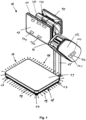
- Fig. 1 shows a scale 10 according to the invention according to a first embodiment.
- the scale includes a weighing module with a housing 18 in which a load cell is accommodated.
- the load cell carries a load cross, which in turn carries a load plate 11.
- the load plate 11 has a downward edge which protrudes over the upper edge of the housing 18.
- a tripod 15 is attached to the weighing module and carries a printer 12 with a label output 16.
- the printer 12 has a transmitter 121 which transmits the length of the paper a full paper roll.
- the printer 12 has a transmitter 123 which transmits the current paper consumption, which is determined by the rotation of a printing roller.
- the printer 12 has a transmitter 122 that sends a reset signal when a new roll of paper is inserted into the printer 12.
- the stand 15 also carries an operator display 13, which is designed as a touchscreen, and a customer display 14 opposite the operator display 13.
- the operator display 13 is an all-in-one PC and includes a computer unit that contains the computer-implemented functions 131 or operator inputs 130 , 132, 133, 134 of the scale ensures.
- the weighing module rests on four feet 17 attached to its corners.
- a light strip 19 is attached all around the outer edge of the housing 18, which is controlled by a control unit depending on the technical condition of the scale.
- Fig. 2 shows a scale 20 according to the invention according to a second embodiment.
- the scale includes a weighing module with a housing 28 in which a load cell is accommodated.
- the load cell carries a load cross, which in turn carries a load plate 21.
- the load plate 21 has a downward edge which protrudes over the upper edge of the housing 28.
- the weighing module rests on a frame 25 which carries a printer 22 with a label output 26.
- the printer 22 has a transmitter 221 which transmits the length of paper that is on a full roll of paper.
- the printer 22 has a transmitter 223 which transmits the current paper consumption, which is determined by the rotation of a printing roller.
- the printer 22 has a transmitter 222 that sends a reset signal when a new roll of paper is inserted into the printer 22. is inserted.
- the frame 25 also carries an operator display 23, which is designed as a touchscreen, and a customer display 24 opposite the operator display 23.
- the operator display 23 is an all-in-one PC and includes a computer unit that contains the computer-implemented functions 230 or operator inputs 230 , 232, 233, 234 of Libra ensures.
- a light strip 29 is attached all around the outer edge of the housing 28 and is controlled by a control unit depending on the technical condition of the scale.
- Fig. 3 shows a section through the housing 18, 28 of a balance 10, 20.
- the housing 18, 28 is a cast metal housing and can take on complex shapes.
- a load cell 30 is screwed to a base 35 with screws 34.
- the load cell 30 comprises a fixed section 31 screwed to the housing 18, 28, a deformation section 32 and a movable section 33, on which a load cross 39 with a fastening 38 is attached.
- the load cross 39 carries the load plate 11, 21 of the scale, with rubber buffers 40 being attached between the load cross 39 and the load plate 11, 21.
- the load plate 11, 21 includes a bend 50 on its edges, so that the load plate 11, 21 projects laterally downward over the upper edges of the housing 18, 28.
- the interior of the housing 18, 28, in which the weighing cell 30 and also a control unit 51 and possibly other components of the scale such as a power supply and the like are located, is covered with a cover 41.
- the housing 18, 28 consists of a base plate and four upwardly projecting side walls.
- the housing is made of cast metal and is therefore made in one piece.
- the transition between the base plate and side walls is slanted.
- a recess 44 is made in the upper area of the side walls, so that a vertical outer wall 47 is set back somewhat on the side walls of the housing 18, 28.
- the carrier 42 of the light strip 19, 29 is glued to the vertical outer wall 47.
- the carrier 42 is made of flexible material and can therefore also be guided around the corners of the housing 18, 28 in the recess 44.
- flexible means that the carrier 42 can be bent at least perpendicular to the plane in which the carrier 42 runs, but not necessarily also in the plane of the carrier 42 itself.
- LED lamps 43 are placed on the carrier 42.
- the LED lamps 43 can be attached in the longitudinal direction of the carrier 42 with a density of up to ten LED lamps 43 per cm.
- Carrier 42 and LED lamps 43 are covered with a protective layer 48 made of silicone on the side of the LED lamps.
- the protective layer 48 is not only applied to the LED lamps 43 themselves before they are mounted on the carrier 42, but is attached over the carrier 42 and the LED lamps 42 after the LED lamps 43 have been mounted on the carrier 42. In this way, a higher density of the LED lamps 43 can be achieved on the carrier 42 and the beam angle for homogeneous light of each LED lamp 43 increases to approximately 170 °.
- a protective layer 48 made of silicone is applied when the LED lamps 43 generate light in the wavelength range from 450 ° nm to 500 ° nm, 500 ° nm to 570 ° nm or 610 ° nm to 760 ° nm and the different LED lamps 43 in regular arrangements on the carrier 42 are arranged.
- the light strip 19, 29 can be made to light up in RGB colors via the control unit 51.
- the recess 44 with carrier 42, LED lamps 43 and protective layer 48 is covered by a diffuser 49.
- the diffuser 49 offers mechanical protection for the light strip 19, 29 and refracts the light at the same time, so that the light strip 19, 29 acts like a homogeneous light source.
- the diffuser 49 can be structured on its outer surface, that is, surface-processed.
- the effect that the light strip 19, 29 acts like a homogeneous light source is due to the high density of LED lamps 43 and the common protective layer 48 made of silicone on the LED lamps 43 and reinforced or completed by the diffuser 49 and the external structuring of the diffuser 49.
- the diffuser 49 rests on surfaces 45, 46 of the housing 18, 28 above and below the recess 44 and is glued to these surfaces 45, 46, locked or screwed to them with a latching connection.
- the diffuser 49 is an annular component that is pushed over the housing 18, 28 from below and fits positively onto the side walls of the housing 18, 28.
- the diffuser 49 is made of translucent material, in particular translucent polycarbonate.
- the control unit 51 includes a state machine 52, which represents at least one technical state of the scale.
- the control unit controls the light strip 19, 29 based on the state of the state machine 52.
- the technical state that is represented by the state machine can be a paper supply in a printer, a difference to a target weight that is formed by the weight determined by the load cell and the target weight, an outdated software version that needs to be updated through updates, a speed of various weight recording steps or processing steps entered via an operator display or that an operator has correctly identified themselves on the scale via the operator display.
- the light strip can be controlled, for example, in different colors (red, yellow, green) for an RGB light strip or as glowing or flashing a monochrome light tape.
- Fig. 4 shows a schematic representation of the control unit 51 and the state machine 52 implemented in the control unit Fig. 4 different state machines 52a, 52b, 52c, 52d, 52e, 52f, 52g, all or only some of which can be implemented in a control unit 51 of a scale 10, 20 according to the invention.
- Each state machine 52a, 52b, 52c, 52d, 52e, 52f, 52g is assigned a control module 51a, 51b, 51c, 51d, 51e, 51f, which interacts with the corresponding state machine 52a, 52b, 52c, 52d, 52e, 52f, 52g and part of the control unit 51.
- the first control module 51a receives a target weight 130, 230 from an input device of the scales 10, 20, for example the operator display 13, 23. Alternatively, the first control module 51a receives a target number of pieces 134, 234 from an input device 13, 23 of the scales 10, 20 of products and a specific gravity 133, 233 per product. The first control module 51a calculates a target weight from the target number of pieces 134, 234 and the specific weight 133, 233 per product. The first control module 51a can determine a weight range from the target weight that includes tolerances, in which case the entire weight range is then viewed as the target weight. Furthermore, the first control module 51a receives weight values determined by the weighing cell 30.
- the first state machine 52a switches or remains in a second state 52a2. If the weight determined by the load cell 30 does not correspond to the target weight, the first state machine 52a switches or remains in the first state 52a1.
- the state transitions between the first state 52a1 and the second state 52a2 are indicated in the drawing, although remaining in the corresponding state is not indicated separately for reasons of clarity.
- the second control module 51b receives from a printer 12, 22 a length of paper 121, 221, which is present on an endless roll of direct thermal paper, and a reset signal 122, 222, which states that a full direct thermal roll has been newly inserted into the printer.
- the second control module 51b continuously receives information 123 from the printer 12, 22, 223, how much paper is fed to the print head via the motor-driven printing roller. This corresponds to the direct thermal paper used.
- the second control module 51b forms the difference between the paper length 121, 221 on the endless roll and the used paper 123, 223. If this difference is smaller than a threshold value, in particular zero, that is, the paper supply of the label roll has been used up, the second control module 51b switches the second state machine 52b into the first state 52b1.
- the second state machine 52b remains in the second state 52b2. If a paper roll is filled and the second control module 51b receives a corresponding reset signal 122, 222 from the printer 12, 22, the second control module 51b moves the second state machine 52b to the second state 52b2.
- the third control module 51c receives a request 131 to update 231 updates for the software from a computer unit of the scale 10, 20, which is integrated, for example, in the operator display 13, 23 of the scale as an all-in-on computer.
- the third control module 51c causes the third state machine 52c to transition to the first state 52c1. If the third control module 51c receives from the scales 10, 20 that the updates have been installed, the third control module 51c causes the third state machine 52c to transition to the second state 52c2.
- the fourth control module 51d receives information 132, 232 from a computer unit of the scale 10, 20, which is integrated, for example, in the operator display 13, 23 of the scale as an all-in-on computer, information 132, 232 as to whether an operator is currently registered for operator sales at the scale is. If an operator has logged in, the fourth control module 51d causes the fourth state machine 52d to transition to the first state 52d1. The fourth control module 51d receives the information 132, 232 from the scales 10, 20 that the operator has completed the operating process and thus the scales again is free for further operators, the fourth control module 51d causes the fourth state machine 52d to transition to the second state 52d2.
- the load cell 30 If the load cell 30 is loaded with objects during operation that exceed the maximum permissible weight of the load cell 30, this represents an overload situation. In this case, the load cell 30 issues a corresponding warning signal.
- the fifth control module 51e receives a warning signal from the load cell 30 that represents an overload situation and causes the fifth state machine 52e to transition to the first state 52e1. If the fifth control module 51e no longer receives an overload signal from the load cell 30, the fifth control module 51e causes the fifth state machine 52e to transition to the second state 52d2.
- the sixth control module 51f receives a threshold value 135, 235 from a computer unit of the scale 10, 20, which is integrated, for example, in the operator display 13, 23 of the scale as an all-in-on computer, a threshold value 135, 235, indicating how many weighings an operator must carry out per unit of time. In addition, the sixth control module 51f continuously receives the weighings from the weighing cell 30. The sixth control module calculates from this whether the necessary number of weighings per unit of time has been achieved by the operator. The sixth control module 51f moves the sixth state machine 52f to the first state 52f1 if the threshold value 135, 235 is not reached. The sixth control module 51f moves the sixth state machine 52f to the second state 52f2 if the threshold value 135, 235 is reached or exceeded.
- the seventh control module receives a target weight from an input device of the scales 10, 20, for example the operator display 13, 23. Alternatively, the seventh control module receives a target number of products and a specific weight per product from an input device 13, 23 of the scales 10, 20. The seventh control module calculates a target weight from the target number of units and the specific weight per product.
- the seventh control module can determine a weight range from the target weight that includes tolerances, with the entire weight range then being viewed as the target weight.
- the seventh control module as well as the data received from the seventh control module such as target weight, target number of pieces or specific weight per product are in Fig. 4 not shown for reasons of clarity.
- a representation would be analogous to the representation of the first control module 51a.
- the seventh control module receives weight values determined by the weighing cell 30. If a weight value determined by the weighing cell 30 corresponds to the target weight, the seventh state machine 52g switches or remains in a second state 52g2. If the weight determined by the weighing cell 30 falls below the target weight, the seventh state machine 52g switches or remains in the first state 52g1. If the weight determined by the load cell 30 exceeds the target weight, the seventh state machine 52g switches or remains in the third state 52g3.
- the control device 51 includes controllers 53, 54, which control the light strip 19, 29 and supply it with voltage. A selection must be made in advance as to which of the state machines 52a, 52b, 52c, 52d, 52e, 52f supplies the controller with an input signal at a time and which controller 53, 54 controls the light strip 19, 29.
- the light band 19, 29 can only reflect the state of a state machine at a time. This selection must be made by the operator in the operator display 13, 23.
- the first to sixth state machines 52a, 52b, 52c, 52d, 52e, 52f are connected to the first controller 53.
- the seventh state machine is connected to the second controller 54.
- the light strip 19, 29 is a light strip 19, 29 with lamps 43 in the wavelength range from 230 nm to 500 nm (monochrome light strip)
- the light strip 19, 29 flashes.
- the light strip is subjected to a permanent voltage by the controller 53b.
- the second controller 54 controls the light strip 19, 29 and the seventh state machine is in a first state 52g1
- the light strip is supplied with a pulsed voltage of a first frequency by the controller 54a.
- the light strip 19, 29 flashes slowly.
- the seventh state machine is in a third state 52g3, the light strip is supplied with a pulsed voltage of a second frequency by the controller 54c.
- the light strip 19, 29 flashes quickly.
- the seventh state machine 52g is in a second state 52g2
- the light strip is subjected to a permanent voltage by the controller 54b.
- the light strip 19, 29 lights up.
- the light strip 19, 29 is a light strip 19, 29 with a group of second LED lamps 43 with a wavelength range of 500 ° nm to 570 ° nm (green light) and a group of third LED lamps 43 with a If the wavelength range is 610°nm to 760°nm (red light), the following applies: If the first controller 53 controls the light strip 19, 29 and the selected state machine 52a, 52b, 52c, 52d, 52e, 52f is in a first state 52a1, 52b1, 52c1, 52d1, 52e1, 52f1, the group becomes third LED lamps 43 of the light strip are supplied with a permanent voltage by the controller 53a. The light strip 19, 29 lights up red.
- the group of second LED lamps 43 of the light strip is controlled by the controller 53b subjected to permanent tension.
- the second controller 54 controls the light strip 19, 29 and the seventh state machine is in a first state 52f1
- the group of second LED lamps 43 and the group of third LED lamps 43 of the light strip are connected by the controller 54a with one permanent voltage applied.
- the light strip 19, 29 lights up yellow.
- the seventh state machine is in a third state 52f3, the group of third LED lamps 43 of the light strip is supplied with a permanent voltage by the controller 54c.
- the light strip 19, 29 lights up red.
- the seventh state machine 52f is in a second state 52f2
- the group of second LED lamps 43 of the light strip is supplied with a permanent voltage by the controller 53b.
- the light strip 19, 29 lights up green.
- DSP digital signal processor
- ASIC application specific integrated circuit
- FPGA field programmable gate array
- ROM read only memory
- RAM random access memory
- non-volatile memory is provided.
Landscapes
- Physics & Mathematics (AREA)
- General Physics & Mathematics (AREA)
- Cash Registers Or Receiving Machines (AREA)
Priority Applications (1)
| Application Number | Priority Date | Filing Date | Title |
|---|---|---|---|
| EP23000187.7A EP4336154B1 (fr) | 2021-12-31 | 2021-12-31 | Balance de chargement |
Applications Claiming Priority (2)
| Application Number | Priority Date | Filing Date | Title |
|---|---|---|---|
| EP21218510.2A EP4206622B1 (fr) | 2021-12-31 | 2021-12-31 | Balance de magasin |
| EP23000187.7A EP4336154B1 (fr) | 2021-12-31 | 2021-12-31 | Balance de chargement |
Related Parent Applications (2)
| Application Number | Title | Priority Date | Filing Date |
|---|---|---|---|
| EP21218510.2A Division EP4206622B1 (fr) | 2021-12-31 | 2021-12-31 | Balance de magasin |
| EP21218510.2A Division-Into EP4206622B1 (fr) | 2021-12-31 | 2021-12-31 | Balance de magasin |
Publications (3)
| Publication Number | Publication Date |
|---|---|
| EP4336154A2 true EP4336154A2 (fr) | 2024-03-13 |
| EP4336154A3 EP4336154A3 (fr) | 2024-08-14 |
| EP4336154B1 EP4336154B1 (fr) | 2025-05-28 |
Family
ID=79185672
Family Applications (2)
| Application Number | Title | Priority Date | Filing Date |
|---|---|---|---|
| EP23000187.7A Active EP4336154B1 (fr) | 2021-12-31 | 2021-12-31 | Balance de chargement |
| EP21218510.2A Active EP4206622B1 (fr) | 2021-12-31 | 2021-12-31 | Balance de magasin |
Family Applications After (1)
| Application Number | Title | Priority Date | Filing Date |
|---|---|---|---|
| EP21218510.2A Active EP4206622B1 (fr) | 2021-12-31 | 2021-12-31 | Balance de magasin |
Country Status (3)
| Country | Link |
|---|---|
| US (1) | US12504315B2 (fr) |
| EP (2) | EP4336154B1 (fr) |
| ES (1) | ES3035183T3 (fr) |
Cited By (1)
| Publication number | Priority date | Publication date | Assignee | Title |
|---|---|---|---|---|
| DE102024128576A1 (de) | 2024-10-02 | 2026-04-02 | Binder Gmbh | Signalleuchte für ein technisches Gerät sowie technisches Gerät |
Citations (3)
| Publication number | Priority date | Publication date | Assignee | Title |
|---|---|---|---|---|
| DE102009049567A1 (de) | 2009-10-15 | 2011-04-21 | Leifheit Ag | Personenwaage |
| DE202011050040U1 (de) | 2011-05-05 | 2011-07-14 | Beurer Gmbh | Waage |
| DE102011083562A1 (de) | 2011-09-27 | 2013-03-28 | BSH Bosch und Siemens Hausgeräte GmbH | Waage |
Family Cites Families (10)
| Publication number | Priority date | Publication date | Assignee | Title |
|---|---|---|---|---|
| US7163311B2 (en) * | 2004-10-22 | 2007-01-16 | Kramer James F | Foodware having visual sensory stimulating or sensing means |
| US20070186515A1 (en) * | 2006-02-16 | 2007-08-16 | Ruetten Roger M | System for monitoring flexible container usage |
| JP5687924B2 (ja) * | 2011-02-25 | 2015-03-25 | 株式会社イシダ | 計量印字装置 |
| US20160356640A1 (en) * | 2015-06-05 | 2016-12-08 | Joseph M. Freeman | Receptacle Scale for Measuring a Weight of a Receptacle |
| WO2017075439A2 (fr) * | 2015-10-28 | 2017-05-04 | Acera LLC | Source de lumière mobile et portable |
| US9901302B2 (en) * | 2016-01-05 | 2018-02-27 | Tosense, Inc. | Physiological monitoring system featuring floormat and wired handheld sensor |
| WO2017222394A1 (fr) * | 2016-06-20 | 2017-12-28 | Anago Limited | Analyseur de force de coupe |
| US11678753B2 (en) * | 2019-10-06 | 2023-06-20 | James F. Kramer | Foodware system including a dining plate having sensing component, and information and entertainment display |
| US20210262851A1 (en) * | 2020-02-26 | 2021-08-26 | Illinois Tool Works Inc. | Weighing system and method |
| JP7504730B2 (ja) * | 2020-09-04 | 2024-06-24 | 東芝テック株式会社 | 決済装置 |
-
2021
- 2021-12-31 EP EP23000187.7A patent/EP4336154B1/fr active Active
- 2021-12-31 ES ES21218510T patent/ES3035183T3/es active Active
- 2021-12-31 EP EP21218510.2A patent/EP4206622B1/fr active Active
-
2022
- 2022-12-20 US US18/068,541 patent/US12504315B2/en active Active
Patent Citations (3)
| Publication number | Priority date | Publication date | Assignee | Title |
|---|---|---|---|---|
| DE102009049567A1 (de) | 2009-10-15 | 2011-04-21 | Leifheit Ag | Personenwaage |
| DE202011050040U1 (de) | 2011-05-05 | 2011-07-14 | Beurer Gmbh | Waage |
| DE102011083562A1 (de) | 2011-09-27 | 2013-03-28 | BSH Bosch und Siemens Hausgeräte GmbH | Waage |
Cited By (2)
| Publication number | Priority date | Publication date | Assignee | Title |
|---|---|---|---|---|
| DE102024128576A1 (de) | 2024-10-02 | 2026-04-02 | Binder Gmbh | Signalleuchte für ein technisches Gerät sowie technisches Gerät |
| EP4722586A1 (fr) | 2024-10-02 | 2026-04-08 | Binder GmbH | Feu de signalisation pour un appareil technique et appareil technique |
Also Published As
| Publication number | Publication date |
|---|---|
| US12504315B2 (en) | 2025-12-23 |
| EP4336154B1 (fr) | 2025-05-28 |
| EP4206622B1 (fr) | 2025-05-28 |
| EP4336154A3 (fr) | 2024-08-14 |
| EP4206622A1 (fr) | 2023-07-05 |
| US20230213373A1 (en) | 2023-07-06 |
| ES3035183T3 (en) | 2025-08-29 |
Similar Documents
| Publication | Publication Date | Title |
|---|---|---|
| EP1509752B2 (fr) | Dispositif de surveillance de l'etat de fonctionnement d'une balance | |
| DE69425396T2 (de) | Skalierbare dreidimensionale Fenstergrenzen | |
| EP1813920B1 (fr) | Procédé et dispositif destinés au fonctionnement d'une balance | |
| DE69608759T2 (de) | Ruhelagedetektionsvorrichtung und -verfahren | |
| DE102017100512A1 (de) | Innenausstattungsteil mit integriertem bildschirm | |
| DE102009036316A1 (de) | Anzeigevorrichtung für ein Fahrzeug | |
| EP4336154B1 (fr) | Balance de chargement | |
| EP4206621B1 (fr) | Balance de comptoir | |
| DE10063537C1 (de) | Anzeige- und Bedienkopf für eine elektronische Waage | |
| EP3620391B1 (fr) | Dispositif de vérification des dimensions d'un bagage pour le trafic aérien | |
| EP4488974B1 (fr) | Dispositif de vente | |
| DE102016108659A1 (de) | Lineare balkenanzeige | |
| DE2452782C3 (de) | Anzeigevorrichtung unter Benutzung von Flüssigkeitskristallen | |
| WO2024227485A1 (fr) | Dispositif de signalisation | |
| CH643943A5 (de) | Vorrichtung zur messung der schichtdicke von druckfarbe auf einem druckzylinder einer druckerpresse. | |
| DE10103205A1 (de) | Abgesetztes Bedienpult für eine Waage | |
| EP3546900B1 (fr) | Balance avec interrupteurs de proximite | |
| DE202013104425U1 (de) | Bedieneinheit für einen Industrie-Computer mit kombinierter Gesten- und Tastenfeldsteuerung sowie Industrie-Computer damit | |
| DE7906132U1 (de) | Vorrichtung zur anzeige eines gemessenen luftdruckes | |
| WO2017101911A1 (fr) | Station de balayage 3d | |
| DE102012103547A1 (de) | Druckmaschinenleitstand | |
| DE202011004402U1 (de) | Gerät zur Messung der körperlichen Zusammensetzung mit zwei Anzeigen | |
| EP2997509A2 (fr) | Appareil médical | |
| DE202008008457U1 (de) | Oberschalige elektronische Waage | |
| DE2019213A1 (de) | System zur Bestimmung der Sicherheitsmarge des Rotorschubs eines Hubschraubers bzw.zur Bestimmung der Vertikaltragfaehigkeit eines Hubschraubers |
Legal Events
| Date | Code | Title | Description |
|---|---|---|---|
| PUAI | Public reference made under article 153(3) epc to a published international application that has entered the european phase |
Free format text: ORIGINAL CODE: 0009012 |
|
| STAA | Information on the status of an ep patent application or granted ep patent |
Free format text: STATUS: THE APPLICATION HAS BEEN PUBLISHED |
|
| AC | Divisional application: reference to earlier application |
Ref document number: 4206622 Country of ref document: EP Kind code of ref document: P |
|
| AK | Designated contracting states |
Kind code of ref document: A2 Designated state(s): AL AT BE BG CH CY CZ DE DK EE ES FI FR GB GR HR HU IE IS IT LI LT LU LV MC MK MT NL NO PL PT RO RS SE SI SK SM TR |
|
| REG | Reference to a national code |
Ref country code: DE Ref legal event code: R079 Free format text: PREVIOUS MAIN CLASS: G01G0023000000 Ipc: G01G0021280000 Ref country code: DE Ref legal event code: R079 Ref document number: 502021007617 Country of ref document: DE Free format text: PREVIOUS MAIN CLASS: G01G0023000000 Ipc: G01G0021280000 |
|
| PUAL | Search report despatched |
Free format text: ORIGINAL CODE: 0009013 |
|
| STAA | Information on the status of an ep patent application or granted ep patent |
Free format text: STATUS: REQUEST FOR EXAMINATION WAS MADE |
|
| AK | Designated contracting states |
Kind code of ref document: A3 Designated state(s): AL AT BE BG CH CY CZ DE DK EE ES FI FR GB GR HR HU IE IS IT LI LT LU LV MC MK MT NL NO PL PT RO RS SE SI SK SM TR |
|
| RIC1 | Information provided on ipc code assigned before grant |
Ipc: G01G 23/00 20060101ALI20240711BHEP Ipc: G01G 21/28 20060101AFI20240711BHEP |
|
| 17P | Request for examination filed |
Effective date: 20240725 |
|
| RBV | Designated contracting states (corrected) |
Designated state(s): AL AT BE BG CH CY CZ DE DK EE ES FI FR GB GR HR HU IE IS IT LI LT LU LV MC MK MT NL NO PL PT RO RS SE SI SK SM TR |
|
| GRAP | Despatch of communication of intention to grant a patent |
Free format text: ORIGINAL CODE: EPIDOSNIGR1 |
|
| STAA | Information on the status of an ep patent application or granted ep patent |
Free format text: STATUS: GRANT OF PATENT IS INTENDED |
|
| INTG | Intention to grant announced |
Effective date: 20241219 |
|
| GRAS | Grant fee paid |
Free format text: ORIGINAL CODE: EPIDOSNIGR3 |
|
| GRAA | (expected) grant |
Free format text: ORIGINAL CODE: 0009210 |
|
| STAA | Information on the status of an ep patent application or granted ep patent |
Free format text: STATUS: THE PATENT HAS BEEN GRANTED |
|
| AC | Divisional application: reference to earlier application |
Ref document number: 4206622 Country of ref document: EP Kind code of ref document: P |
|
| AK | Designated contracting states |
Kind code of ref document: B1 Designated state(s): AL AT BE BG CH CY CZ DE DK EE ES FI FR GB GR HR HU IE IS IT LI LT LU LV MC MK MT NL NO PL PT RO RS SE SI SK SM TR |
|
| REG | Reference to a national code |
Ref country code: GB Ref legal event code: FG4D Free format text: NOT ENGLISH |
|
| REG | Reference to a national code |
Ref country code: CH Ref legal event code: EP |
|
| REG | Reference to a national code |
Ref country code: IE Ref legal event code: FG4D Free format text: LANGUAGE OF EP DOCUMENT: GERMAN Ref country code: DE Ref legal event code: R096 Ref document number: 502021007617 Country of ref document: DE |
|
| REG | Reference to a national code |
Ref country code: NL Ref legal event code: MP Effective date: 20250528 |
|
| PG25 | Lapsed in a contracting state [announced via postgrant information from national office to epo] |
Ref country code: FI Free format text: LAPSE BECAUSE OF FAILURE TO SUBMIT A TRANSLATION OF THE DESCRIPTION OR TO PAY THE FEE WITHIN THE PRESCRIBED TIME-LIMIT Effective date: 20250528 Ref country code: ES Free format text: LAPSE BECAUSE OF FAILURE TO SUBMIT A TRANSLATION OF THE DESCRIPTION OR TO PAY THE FEE WITHIN THE PRESCRIBED TIME-LIMIT Effective date: 20250528 |
|
| REG | Reference to a national code |
Ref country code: LT Ref legal event code: MG9D |
|
| PG25 | Lapsed in a contracting state [announced via postgrant information from national office to epo] |
Ref country code: GR Free format text: LAPSE BECAUSE OF FAILURE TO SUBMIT A TRANSLATION OF THE DESCRIPTION OR TO PAY THE FEE WITHIN THE PRESCRIBED TIME-LIMIT Effective date: 20250829 Ref country code: NO Free format text: LAPSE BECAUSE OF FAILURE TO SUBMIT A TRANSLATION OF THE DESCRIPTION OR TO PAY THE FEE WITHIN THE PRESCRIBED TIME-LIMIT Effective date: 20250828 |
|
| PG25 | Lapsed in a contracting state [announced via postgrant information from national office to epo] |
Ref country code: NL Free format text: LAPSE BECAUSE OF FAILURE TO SUBMIT A TRANSLATION OF THE DESCRIPTION OR TO PAY THE FEE WITHIN THE PRESCRIBED TIME-LIMIT Effective date: 20250528 Ref country code: PL Free format text: LAPSE BECAUSE OF FAILURE TO SUBMIT A TRANSLATION OF THE DESCRIPTION OR TO PAY THE FEE WITHIN THE PRESCRIBED TIME-LIMIT Effective date: 20250528 |
|
| PG25 | Lapsed in a contracting state [announced via postgrant information from national office to epo] |
Ref country code: BG Free format text: LAPSE BECAUSE OF FAILURE TO SUBMIT A TRANSLATION OF THE DESCRIPTION OR TO PAY THE FEE WITHIN THE PRESCRIBED TIME-LIMIT Effective date: 20250528 |
|
| PG25 | Lapsed in a contracting state [announced via postgrant information from national office to epo] |
Ref country code: HR Free format text: LAPSE BECAUSE OF FAILURE TO SUBMIT A TRANSLATION OF THE DESCRIPTION OR TO PAY THE FEE WITHIN THE PRESCRIBED TIME-LIMIT Effective date: 20250528 |
|
| PG25 | Lapsed in a contracting state [announced via postgrant information from national office to epo] |
Ref country code: RS Free format text: LAPSE BECAUSE OF FAILURE TO SUBMIT A TRANSLATION OF THE DESCRIPTION OR TO PAY THE FEE WITHIN THE PRESCRIBED TIME-LIMIT Effective date: 20250828 |
|
| PG25 | Lapsed in a contracting state [announced via postgrant information from national office to epo] |
Ref country code: IS Free format text: LAPSE BECAUSE OF FAILURE TO SUBMIT A TRANSLATION OF THE DESCRIPTION OR TO PAY THE FEE WITHIN THE PRESCRIBED TIME-LIMIT Effective date: 20250928 |
|
| PG25 | Lapsed in a contracting state [announced via postgrant information from national office to epo] |
Ref country code: LV Free format text: LAPSE BECAUSE OF FAILURE TO SUBMIT A TRANSLATION OF THE DESCRIPTION OR TO PAY THE FEE WITHIN THE PRESCRIBED TIME-LIMIT Effective date: 20250528 |
|
| PG25 | Lapsed in a contracting state [announced via postgrant information from national office to epo] |
Ref country code: DK Free format text: LAPSE BECAUSE OF FAILURE TO SUBMIT A TRANSLATION OF THE DESCRIPTION OR TO PAY THE FEE WITHIN THE PRESCRIBED TIME-LIMIT Effective date: 20250528 Ref country code: SM Free format text: LAPSE BECAUSE OF FAILURE TO SUBMIT A TRANSLATION OF THE DESCRIPTION OR TO PAY THE FEE WITHIN THE PRESCRIBED TIME-LIMIT Effective date: 20250528 |
|
| PGFP | Annual fee paid to national office [announced via postgrant information from national office to epo] |
Ref country code: FR Payment date: 20251218 Year of fee payment: 5 |
|
| PG25 | Lapsed in a contracting state [announced via postgrant information from national office to epo] |
Ref country code: CZ Free format text: LAPSE BECAUSE OF FAILURE TO SUBMIT A TRANSLATION OF THE DESCRIPTION OR TO PAY THE FEE WITHIN THE PRESCRIBED TIME-LIMIT Effective date: 20250528 |
|
| PG25 | Lapsed in a contracting state [announced via postgrant information from national office to epo] |
Ref country code: EE Free format text: LAPSE BECAUSE OF FAILURE TO SUBMIT A TRANSLATION OF THE DESCRIPTION OR TO PAY THE FEE WITHIN THE PRESCRIBED TIME-LIMIT Effective date: 20250528 |
|
| PG25 | Lapsed in a contracting state [announced via postgrant information from national office to epo] |
Ref country code: SK Free format text: LAPSE BECAUSE OF FAILURE TO SUBMIT A TRANSLATION OF THE DESCRIPTION OR TO PAY THE FEE WITHIN THE PRESCRIBED TIME-LIMIT Effective date: 20250528 |
|
| REG | Reference to a national code |
Ref country code: CH Ref legal event code: U11 Free format text: ST27 STATUS EVENT CODE: U-0-0-U10-U11 (AS PROVIDED BY THE NATIONAL OFFICE) Effective date: 20260219 |
|
| REG | Reference to a national code |
Ref country code: DE Ref legal event code: R097 Ref document number: 502021007617 Country of ref document: DE |
|
| PG25 | Lapsed in a contracting state [announced via postgrant information from national office to epo] |
Ref country code: RO Free format text: LAPSE BECAUSE OF FAILURE TO SUBMIT A TRANSLATION OF THE DESCRIPTION OR TO PAY THE FEE WITHIN THE PRESCRIBED TIME-LIMIT Effective date: 20250528 |
|
| PLBE | No opposition filed within time limit |
Free format text: ORIGINAL CODE: 0009261 |
|
| STAA | Information on the status of an ep patent application or granted ep patent |
Free format text: STATUS: NO OPPOSITION FILED WITHIN TIME LIMIT |
|
| PGFP | Annual fee paid to national office [announced via postgrant information from national office to epo] |
Ref country code: GB Payment date: 20260212 Year of fee payment: 5 |
|
| REG | Reference to a national code |
Ref country code: CH Ref legal event code: L10 Free format text: ST27 STATUS EVENT CODE: U-0-0-L10-L00 (AS PROVIDED BY THE NATIONAL OFFICE) Effective date: 20260409 |
|
| PGFP | Annual fee paid to national office [announced via postgrant information from national office to epo] |
Ref country code: DE Payment date: 20260217 Year of fee payment: 5 |
|
| PGFP | Annual fee paid to national office [announced via postgrant information from national office to epo] |
Ref country code: IT Payment date: 20260227 Year of fee payment: 5 |
|
| PGFP | Annual fee paid to national office [announced via postgrant information from national office to epo] |
Ref country code: CH Payment date: 20260219 Year of fee payment: 5 |