EP4336513B1 - Production d'enregistrements radiologiques synthétiques - Google Patents
Production d'enregistrements radiologiques synthétiques Download PDFInfo
- Publication number
- EP4336513B1 EP4336513B1 EP23163650.7A EP23163650A EP4336513B1 EP 4336513 B1 EP4336513 B1 EP 4336513B1 EP 23163650 A EP23163650 A EP 23163650A EP 4336513 B1 EP4336513 B1 EP 4336513B1
- Authority
- EP
- European Patent Office
- Prior art keywords
- representation
- examination
- transformed
- synthetic
- input
- Prior art date
- Legal status (The legal status is an assumption and is not a legal conclusion. Google has not performed a legal analysis and makes no representation as to the accuracy of the status listed.)
- Active
Links
Images

Classifications
-
- G—PHYSICS
- G16—INFORMATION AND COMMUNICATION TECHNOLOGY [ICT] SPECIALLY ADAPTED FOR SPECIFIC APPLICATION FIELDS
- G16H—HEALTHCARE INFORMATICS, i.e. INFORMATION AND COMMUNICATION TECHNOLOGY [ICT] SPECIALLY ADAPTED FOR THE HANDLING OR PROCESSING OF MEDICAL OR HEALTHCARE DATA
- G16H50/00—ICT specially adapted for medical diagnosis, medical simulation or medical data mining; ICT specially adapted for detecting, monitoring or modelling epidemics or pandemics
- G16H50/70—ICT specially adapted for medical diagnosis, medical simulation or medical data mining; ICT specially adapted for detecting, monitoring or modelling epidemics or pandemics for mining of medical data, e.g. analysing previous cases of other patients
-
- G—PHYSICS
- G16—INFORMATION AND COMMUNICATION TECHNOLOGY [ICT] SPECIALLY ADAPTED FOR SPECIFIC APPLICATION FIELDS
- G16H—HEALTHCARE INFORMATICS, i.e. INFORMATION AND COMMUNICATION TECHNOLOGY [ICT] SPECIALLY ADAPTED FOR THE HANDLING OR PROCESSING OF MEDICAL OR HEALTHCARE DATA
- G16H30/00—ICT specially adapted for the handling or processing of medical images
- G16H30/40—ICT specially adapted for the handling or processing of medical images for processing medical images, e.g. editing
-
- G—PHYSICS
- G16—INFORMATION AND COMMUNICATION TECHNOLOGY [ICT] SPECIALLY ADAPTED FOR SPECIFIC APPLICATION FIELDS
- G16H—HEALTHCARE INFORMATICS, i.e. INFORMATION AND COMMUNICATION TECHNOLOGY [ICT] SPECIALLY ADAPTED FOR THE HANDLING OR PROCESSING OF MEDICAL OR HEALTHCARE DATA
- G16H50/00—ICT specially adapted for medical diagnosis, medical simulation or medical data mining; ICT specially adapted for detecting, monitoring or modelling epidemics or pandemics
- G16H50/20—ICT specially adapted for medical diagnosis, medical simulation or medical data mining; ICT specially adapted for detecting, monitoring or modelling epidemics or pandemics for computer-aided diagnosis, e.g. based on medical expert systems
Definitions
- the present disclosure relates to the technical field of radiology.
- Subject matters of the present disclosure are a novel approach for training a machine learning model to generate synthetic radiological images based on measured radiological images and the use of the trained machine learning model to generate synthetic radiological images.
- Medical imaging is the technique and process of imaging the inside of the body for clinical analysis and medical intervention, as well as to visually depict the function of specific organs or tissues.
- the purpose of medical imaging is to reveal internal structures hidden beneath the skin and bones and to diagnose and/or treat disease.
- Machine learning models are used, among other things, to segment radiological images, to induce contrast enhancements in radiological images and/or to predict a radiological image in a temporal sequence of radiological images.
- WO2019/074938A1 discloses a method for reducing the amount of contrast agent when generating radiological images using an artificial neural network.
- US 10,997,716 B2 also discloses a method for reducing the amount of contrast agent when generating radiological images using an artificial neural network.
- WO2021/052896A1 discloses a method in which an MRI image of a patient's liver during the hepatobiliary phase is not generated by measurement, but is calculated (predicted) on the basis of MRI images from one or more previous phases in order to shorten the patient's stay in the MRI scanner.
- WO2021/197996A1 discloses a method in which MRI images after the application of a so-called blood pool contrast agent are simulated using a machine learning model.
- At least one measured radiological image of an examination area of an object under examination is fed to a trained machine learning model and the model generates a synthetic radiological image.
- Both the fed radiological image and the synthetic radiological image are representations of the examination area in a spatial representation.
- representations of an examination region of an examination object can be predicted.
- a predicted representation is also referred to as a synthetic representation in this disclosure.
- the "object under investigation” is usually a living being, preferably a mammal, most preferably a human.
- the "area of investigation” is a part of the object of investigation, for example an organ or part of an organ such as the liver, brain, heart, kidney, lung, stomach, intestine, pancreas or part of the organs mentioned or several organs or another part of the body.
- the examination area is the liver or part of the liver of a human.
- the examination area also called field of view (FOV) represents a volume that is depicted in radiological images.
- the examination area is typically determined by a radiologist, for example on an overview image ( localizer ).
- the examination area can alternatively or additionally be determined automatically, for example on the basis of a selected protocol.
- a "representation of the field of study” is usually the result of a radiological examination.
- Radiology is the branch of medicine that deals with the use of predominantly electromagnetic radiation and (including ultrasound diagnostics) mechanical waves for diagnostic, therapeutic and/or scientific purposes.
- other ionizing radiation such as gamma radiation or electrons are also used.
- imaging since a major purpose is imaging, other imaging methods such as sonography and magnetic resonance imaging (MRI) are also considered radiology, although these methods do not use ionizing radiation.
- MRI magnetic resonance imaging
- the term "radiology" in the sense of the present invention therefore includes in particular the following examination methods: computer tomography, magnetic resonance imaging, sonography.
- the radiological examination is a magnetic resonance imaging or computed tomography examination. Most preferably, the radiological examination is a magnetic resonance imaging examination.
- Magnetic resonance imaging abbreviated to MRI ( Magnetic Resonance Imaging ) is an imaging technique that is used primarily in medical diagnostics to depict the structure and function of tissues and organs in the human or animal body.
- MR imaging the magnetic moments of protons in an object under investigation are aligned in a basic magnetic field so that a macroscopic magnetization is established along a longitudinal direction. This is then deflected from the rest position by irradiating high frequency (HF) pulses (excitation). The return of the excited states to the rest position (relaxation) or the magnetization dynamics is then detected as relaxation signals using one or more HF receiving coils.
- HF high frequency
- the recorded relaxation signals or the detected MR data are initially available as raw data in the frequency space (so-called k-space data) and can be transformed into the spatial space (image space) by subsequent inverse Fourier transformation.
- a representation of the examination region within the meaning of the present disclosure can be an MRI image, a computer tomogram, an ultrasound image or the like, or the representation of the examination region can be generated from one or more MRI images, computer tomograms, ultrasound images or the like.
- a representation of the examination area within the meaning of the present disclosure can be a representation in the spatial space (image space) or a representation in the frequency space.
- the examination area is usually represented by a large number of image elements (pixels or voxels), which can be arranged in a grid, for example, and where each image element represents a part of the examination area.
- image elements pixels or voxels
- DICOM Digital Imaging and Communications in Medicine
- DICOM is an open standard for storing and exchanging information in medical image data management.
- the area under investigation is represented by a superposition of fundamental oscillations.
- the area under investigation can be represented by a sum of sine and cosine functions with different amplitudes, frequencies and phases.
- the amplitudes and phases can be plotted as a function of the frequencies, for example in a two- or three-dimensional representation.
- the lowest frequency (origin) is placed in the center. The further away you are from this center, the higher the frequencies.
- Each frequency can be assigned an amplitude with which the frequency is represented in the frequency space representation and a phase that indicates the extent to which the respective oscillation is shifted compared to a sine or cosine oscillation.
- a representation in the spatial domain can be converted (transformed) into a representation in the frequency domain, for example, using a Fourier transformation.
- a representation in the frequency domain can be converted (transformed) into a representation in the spatial domain, for example, using an inverse Fourier transformation.
- a synthetic representation of the examination area of the examination object in a second state can be generated on the basis of at least one representation of an examination area of an examination object in a first state.
- the at least one representation on the basis of which the (trained) machine learning model generates the synthetic representation is also referred to as the input representation in this description.
- the synthetic representation typically represents the same area of investigation of the same object of investigation as the at least one input representation on whose generation the synthetic representation is based.
- the input representation represents the area of investigation in a first state; the synthetic representation represents the area of investigation in a second state.
- the first state and the second state are different states.
- the synthetic representation represents the area of investigation at a different time than the input representation.
- the machine learning model is configured and trained to generate a synthetic representation based on at least one input representation of an examination area of an examination object, which represents the examination area at a first point in time before and/or after the application of an amount of contrast agent, which synthetic representation represents the examination area at a second point in time after the application of the amount of contrast agent.
- a trained machine learning model can, for example, be as in WO2021/052896A1 described to reduce the amount of time a subject must spend in an MRI or CT scanner.
- a “machine learning model” can be understood as a computer-implemented data processing architecture.
- the model can receive input data and provide output data based on these input data and model parameters.
- the model can learn a relationship between the input data and the output data through training. During training, model parameters can be adjusted to produce a desired output for a given input.
- the model When training such a model, the model is presented with training data from which it can learn.
- the trained machine learning model is the result of the training process.
- the training data includes the correct output data (target data) that the model should generate based on the input data.
- patterns are recognized that map the input data to the target data.
- the input data of the training data is fed into the model and the model generates output data.
- the output data is compared with the target data.
- Model parameters are changed so that the deviations between the output data and the target data are reduced to a (defined) minimum.
- An optimization method such as a gradient method can be used to modify the model parameters with a view to reducing the deviations.
- the deviations can be quantified using a loss function.
- a loss function can be used to calculate an error ( loss ) for a given pair of output data and target data.
- the goal of the training process can be to change (adjust) the parameters of the machine learning model so that the error is reduced to a (defined) minimum for all pairs of the training data set.
- the error function can be the absolute difference between those numbers.
- a high absolute error may mean that one or more model parameters need to be changed significantly.
- difference metrics between vectors such as the mean square error, a cosine distance, a norm of the difference vector such as a Euclidean distance, a Chebyshev distance, an Lp norm of a difference vector, a weighted norm, or another type of difference metric of two vectors can be chosen as the error function.
- an element-wise difference metric can be used.
- the output data can be transformed, e.g. into a one-dimensional vector, before calculating an error value.
- the machine learning model is trained using training data to generate a synthetic representation of an examination area of an examination object in a second state based on at least one representation of the examination area of the examination object in a first state.
- the training data includes a set of input data and target data for each of a plurality of test objects.
- the term multitude means at least ten, preferably more than one hundred.
- Each set of input data and target data comprises at least one input representation of an examination area of the examination object in a first state as input data.
- Each set of input data and target data further comprises a target representation of the examination area of the examination object in a second state and a transformed target representation as target data.
- the area of investigation is usually the same for all objects under investigation.
- the transformed target representation represents at least part of the examination area of the examination object in the second state.
- the transformed target representation represents at least part of the investigation area of the investigation object in the frequency space.
- the transformed target representation represents at least part of the investigation area of the investigation object in the spatial space.
- the transformed target representation in frequency space can be generated from a target representation in spatial space, for example by Fourier transformation.
- the transformed target representation in the spatial domain can be generated from a target representation in the frequency domain, for example by inverse Fourier transformation.
- At least one input representation of the area of investigation is fed to the machine learning model for each object of investigation of the plurality of objects of investigation.
- the model generates a synthetic representation based on the at least one input representation of the area of investigation and on the basis of model parameters.
- the synthetic input representation preferably (but not necessarily) also represents the investigation area in the spatial space.
- the synthetic representation preferably (but not necessarily) also represents the investigation area in frequency space.
- the machine learning model can also be configured and trained to generate a synthetic representation of the investigation area based on the at least one input representation of the investigation area, which i) represents the investigation area in frequency space if the at least one representation represents the investigation area in spatial space, or ii) represents the investigation area in spatial space if the at least one representation represents the investigation area in frequency space.
- the machine learning model can be configured and trained to carry out (among other things) a transformation from spatial to frequency space or vice versa.
- a transformed synthetic representation is generated from or to the synthetic representation.
- the transformed synthetic representation represents at least a part of the examination area in the second state in the frequency space.
- the synthetic representation represents the examination area in the second state in the frequency space
- the transformed synthetic representation represents at least a part of the examination area in the second state in the spatial space.
- the generation of the transformed synthetic representation can take place by transforming the synthetic representation and/or the machine learning model can be configured and trained to generate a transformed synthetic representation based on the at least one input representation.
- the deviations i) between at least part of the synthetic representation and at least part of the target representation and ii) between at least part of the transformed synthetic representation and at least part of the transformed target representation are quantified.
- the error function may have two terms, a first term for quantifying the deviations between at least a part of the synthetic representation and at least a part of the target representation and a second term for quantifying the deviations between at least a part of the transformed synthetic representation and at least a part of the transformed target representation.
- the terms can be added together in the error function, for example.
- the terms can be weighted differently in the error function.
- L is the (total) error function
- L 1 is a term that represents the deviations between the synthetic representation and the target representation
- L 2 is a term that quantifies the deviations between the transformed synthetic representation and the transformed target representation
- ⁇ 1 and ⁇ 2 are weight factors that can, for example, take values between 0 and 1 and give the two terms a different weight in the error function. It is possible that the weight factors are kept constant or varied during the training of the machine learning model.
- error functions examples include L1 error function ( L1 loss ), L2 error function ( L2 loss ), Lp error function (Lp loss), structural similarity index measure (SSIM)), VGG error function (VGG loss), perceptual error function ( perceptual loss ) or a combination of the above functions or other error functions. Further details on error functions can be found in the scientific literature (see e.g.: R. Mechrez et al.: The ContextualLoss for Image Transformation with Non-Aligned Data, 2018, arXiv:1803.02077v4 ; H. Zhao et al.: Loss Functions for Image Restoration with Neural Networks, 2018, arXiv:1511.08861v3 ).
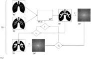
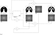
- Fig. 1 shows an example and schematically the process of training the machine learning model. Training is done using training data.
- training data TD for an examination object are shown.
- the training data TD comprise as input data a first input representation R1 of an examination area of the examination object and a second input representation R2 of the examination area of the examination object.
- the first input representation R1 and the second input representation R2 represent the examination area in spatial space.
- the first input representation R1 represents the examination area in a first state, for example at a first point in time before or after the application of a contrast agent.
- the second input representation R2 represents the examination area in a second state, for example at a second point in time after the application of a contrast agent.
- the training data TD also includes a target representation TR as target data.
- the target representation TR also represents the examination area in spatial space.
- the target representation TR represents the examination area in a third state, for example at a third time after the application of a contrast agent.
- the machine learning model MLM is trained to predict the target representation TR based on the first input representation R1 and the second input representation R2 as well as on the basis of model parameters MP.
- the first input representation R1 and the second input representation R2 are fed to the machine learning model as input data.
- the machine learning model is configured to generate a synthetic representation SR.
- the synthetic representation SR is discussed in Fig. 1
- a transformed synthetic representation SR T is generated by means of a transformation T (e.g. a Fourier transformation).
- a transformed target representation TR T is generated from the target representation TR by means of the transformation T.
- the transformed synthetic representation SR T and the transformed target representation TR T are frequency space representations of the examination area in the third state.
- a first error function L 1 is used to quantify the deviations between the synthetic representation SR and the target representation TR.
- a second error function Lz is used to quantify the deviations between the transformed synthetic representation SR T and the transformed target representation TR T.
- the errors calculated using the error functions L 1 and L 2 are combined in a total error function L to form a total error (e.g. by addition).
- Model parameters MP are modified with a view to reducing the total error.
- the reduction of the total error can be achieved using an optimization method, for example using a gradient method.
- the process is repeated for a large number of test objects until the total error reaches a predefined (desired) minimum.
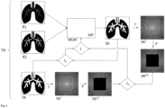
- the transformed synthetic representation and the transformed target representation are each reduced to one or more predefined parts. This is shown by way of example and schematically in Fig. 2 shown.
- the entire frequency space is not considered in the calculation using the error function L 2.
- the representations in the frequency space are reduced to a range with low frequencies; the higher frequencies are discarded.
- contrast information is predominantly encoded, while in the range of higher frequencies, information on fine structures is predominantly encoded.
- the machine learning model in the Fig. 2 in addition to generating the synthetic representation SR, it is trained to correctly reproduce the low frequencies in particular and thus a special focus is placed on contrast information.
- Fig. 3 shows another example in which the entire frequency range is not considered, but a focus is placed on a defined frequency range.
- the Fig. 3 The process shown corresponds to the process described in Fig. 2 is shown, with the difference that the function P ensures that the transformed target representation TR T and the transformed synthetic representation SR T are each reduced to a portion with higher frequencies, while low frequencies are discarded (the low frequency values in this example are set to the value zero, which is represented by the color black).
- the machine learning model in the Fig. 3 example shown in addition to the generation of the synthetic representation SR is trained to reproduce the higher frequencies correctly, thus placing particular emphasis on the correct reproduction of fine structures.
- the part to which the frequency space is reduced may also include other than those in Fig. 2 and Fig. 3 can take on the shapes and sizes shown. Furthermore, several parts can be selected and the frequency space representations restricted to several parts (areas). For example, it is possible to divide the frequency space into different areas and to generate frequency space representations of the examination area for several or all areas, in which only the frequencies of the respective area occur. In this way, different frequency ranges can be weighted/taken into account to different degrees during training.
- the representations R1, R2, TR and SR are representations in the spatial space. It is also possible that one or more of these representations are frequency space representations.
- the transformed synthetic representation SR T and the transformed target representation TR T are representations in the spatial space
- a part (or several parts) in the representations can also be selected and the representations can be reduced to this part (these parts).
- the error calculation focuses on features in the spatial space that are found in the selected part (the selected parts).
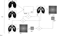
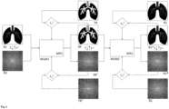
- Fig. 4 , Fig. 5 , Fig. 6 , Fig. 7 and Fig. 8 show further embodiments of the training procedure.
- the training data for each examination object comprise at least one input representation R1 of an examination area in a first state and a target representation TR of the examination area in a second state.
- the at least one input representation R1 and the target representation TR can each be a representation in the spatial space or a representation in the frequency space.
- the input representation R1 and the target representation TR are representations in the spatial space.
- the machine learning model MLM is trained to predict the target representation TR on the basis of at least one input representation R1.
- a transformed input representation R2 is generated on the basis of the input representation R1 using a transformation T.
- a transformed target representation TR T is generated on the basis of the target representation TR using the transformation T.
- the transformed input representation R2 and the transformed target representation TR T are representations of the examination region in the frequency domain.
- the transformed input representation R2 represents the examination region (like the input representation R1) in the first state;
- the transformed target representation TR T represents the examination region (like the target representation TR) in the second state.
- the input representation R1 can be obtained by an inverse transformation T -1 based on the transformed input representation R2.
- a target representation TR can be obtained by the inverse transformation T -1 based on the transformed target representation TR T.
- the inverse transformation T -1 is the inverse transformation of the transformation T, which is indicated by the index -1.
- the reference to the inverse transformation is intended to clarify that the training data must contain at least one input representation (R1 or R2) and one target representation (TR or TR7); the other (R2 or R1, or TR T or TR) can be obtained by transformation or inverse transformation from the existing representation. This applies generally and not only to the Fig. 4 illustrated embodiment.
- both the input representation R1 and the transformed input representation R2 are fed to the machine learning model MLM.
- the machine learning model MLM is configured to generate both a synthetic representation SR and a transformed synthetic representation SR T.
- the deviations between at least part of the synthetic representation SR and at least part of the target representation TR are quantified using a first error function L 1 .
- the deviations between at least part of the transformed synthetic representation SR T and at least part of the transformed target representation TR T are quantified using a second error function L 2 .
- the Fig. 4 The dashed white frames drawn in the transformed representations are intended to express that the calculation of the error is carried out using the error function as in relation to Fig. 3 described does not have to be based on the entire frequency space representation, but that the transformed representations can be reduced to a frequency range (or several frequency ranges). Analogously, the position space representations SR and TR can be reduced to a part (or several parts) in the error calculation (also shown by the dashed white frames). This also applies analogously to the other embodiments and not only to those in Fig. 4 illustrated embodiment.
- the errors calculated using the error functions L 1 and L 2 are combined to form a total error function L (e.g. by addition).
- Model parameters MP are modified with a view to reducing the total error. This can be done using an optimization method, for example a gradient method.
- the process is repeated for a large number of test objects until the total error reaches a predefined (desired) minimum.
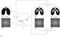
- the synthetic representation SR and the transformed synthetic representation SR T must be able to be converted into one another in the same way as the target representation TR and the transformed target representation TR T . It is possible to introduce a further error function that evaluates the quality of such a conversion. It is therefore possible to generate a transformed synthetic representation from the synthetic representation SR by means of the transformation T and to quantify the deviations between this synthetic representation generated by transformation and the transformed synthetic representation generated by the machine learning model using a third error function L 3 . Alternatively or additionally, it is possible to generate a synthetic representation from the transformed synthetic representation SR T by means of the inverse transformation T -1 and to quantify the deviations between this synthetic representation generated by inverse transformation and the synthetic representation generated by the machine learning model using a third error function L 3 .
- Fig. 5 The example of generating a transformed synthetic representation SR T * by transforming T from the synthetic representation SR is shown.
- the error function L 3 quantifies the deviations between the transformed synthetic representation SR T * generated by transformation and the transformed synthetic representation SR T generated by the machine learning model MLM.
- the error functions L 1 , L 2 and L 3 are combined in an overall error function L (e.g. by addition).
- the individual terms can carry different weights, whereby the weights can be kept constant or varied over the course of training.
- a variation of the Fig. 4 and Fig. 5 shown embodiments is that the machine learning model MLM is not fed both input representations R1 and R2, but only one of the two.
- the machine learning model can be configured and trained to generate the other.
- Fig. 6 shows schematically a further embodiment of the training method.
- two machine learning models are used, a first model MLM1 and a second model MLM2.
- the first machine learning model MLM1 is trained to predict a target representation TR and/or a transformed target representation TR T from an input representation R1 and/or R2.
- the second machine learning model MLM2 is trained to predict a target representation SR and/or a predicted to predict (reconstruct) the original input representation R1 and/or R2 from the transformed target representation SR T.
- the machine learning models thus perform a cycle that can improve the prediction quality of the first model MLM1 (which is used in the subsequent prediction).
- At least one input representation R1 and/or at least one transformed input representation R2 is supplied to the first machine learning model MLM1 as input data.
- the first model MLM1 is configured to generate a synthetic representation SR and/or a transformed synthetic representation SR T based on the input data and model parameters MP1.
- a transformed synthetic representation SR T can also be generated by transformation T of the synthetic representation SR.
- a synthetic representation SR can also be generated by inverse transformation T -1 of the transformed synthetic representation SR T.
- Deviations between the synthetic representation SR and the target representation TR can be quantified using an error function L 1 1. Deviations between the transformed synthetic representation SR T and the transformed target representation TR T can be quantified using an error function L 2 1 .
- Deviations between a synthetic representation obtained by transformation T and the synthetic representation SR generated by the model MLM1 can be quantified using an error function L 3 1 (in Fig. 6 not shown).
- deviations between a transformed synthetic representation obtained by transformation T and the transformed synthetic representation SR T generated by the model MLM1 can be quantified using an error function L 4 1 (in Fig. 6 not shown).
- the error functions L 1 1 , L 2 1 and, if present, L 3 1 and/or L 4 1 can be combined to form an overall error function (in Fig. 6 not shown).
- Model parameters MP1 can be modified to reduce the total error.
- the synthetic representation SR and/or the transformed synthetic representation SR T is/are fed to the second machine learning model MLM2.
- the second model MLM2 is configured to reconstruct (predict) the first input representation R1 and/or the second input representation R2.
- the second model MLM2 is configured to generate a predicted first input representation R1* and/or a predicted second input representation R2* based on the synthetic representation SR, the transformed synthetic representation SR T and based on model parameters MP2.
- a second input representation R2* can also be generated by transformation T of the first input representation R1* and/or a first input representation R1* can also be generated by inverse transformation T -1 of the second input representation R2*.
- Deviations between the predicted first input representation R1* and the first input representation R1 can be quantified using an error function L 1 2 .
- Deviations between the predicted second input representation R2* and the second input representation R2 can be quantified using an error function L 2 2 .
- Deviations between an input representation R1* obtained by inverse transformation T -1 and the input representation R1* generated by the model MLM2 can be quantified using an error function L 3 2 (in Fig. 6 not shown).
- deviations between an input representation R2* obtained by transformation and the input representation R2* generated by the model MLM2 can be quantified using an error function L 4 2 (in Fig. 6 not shown).
- the error functions L 1 2 , L 2 2 and, if present, L 3 2 and/or L 4 2 can be combined to form a total error function (in Fig. 6 not shown).
- Model parameters MP2 can be modified to reduce the total error.
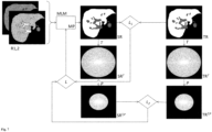
- Fig. 7 shows schematically another example of a method for training a machine learning model.
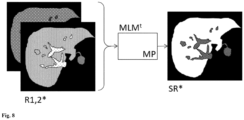
- Fig. 8 shows the use of the trained machine learning model for prediction.
- the Fig. 7 and Fig. 8 The example shown concerns the acceleration of a magnetic resonance imaging examination of the liver of an examination subject using a hepatobiliary contrast agent.
- hepatobiliary contrast agent is the disodium salt of gadoxetic acid (Gd-EOB-DTPA disodium), which is used in the US Patent No. 6,039,931A and is commercially available under the brand names Primovist ® and Eovist ® .
- a hepatobiliary contrast agent can be used to detect tumors in the liver.
- the blood supply to healthy liver tissue is primarily via the portal vein (vena portae), while the hepatic artery (arteria hepatica) supplies most primary tumors.
- the hepatic artery (arteria hepatica) supplies most primary tumors.
- a time delay can be observed between the signal increase of the healthy liver parenchyma and the tumor.
- benign lesions such as cysts, hemangiomas and focal nodular hyperplasia (FNH) are often found in the liver. These must be differentiated from malignant tumors for appropriate treatment planning.
- Primovist ® can be used to detect benign and malignant focal liver lesions. It provides information about the nature of these lesions using T1-weighted MRI. The different blood supply to the liver and tumor and the temporal course of contrast enhancement are used for differentiation.
- Primovist ® leads to a significant signal enhancement in the healthy liver parenchyma 10-20 minutes after injection (in the hepatobiliary phase), while lesions containing no or only a few hepatocytes, e.g. metastases or moderately to poorly differentiated hepatocellular carcinomas (HCCs), appear as darker areas.
- HCCs poorly differentiated hepatocellular carcinomas
- Tracking the distribution of the contrast agent over time offers a good opportunity for the detection and differential diagnosis of focal liver lesions; however, the examination takes a relatively long time. During this time, patient movements should be avoided as much as possible in order to minimize motion artifacts in the MRI images. The long-term restriction of movement can be uncomfortable for a patient.
- MRI images of a patient's liver during the hepatobiliary phase should not be generated by measurement, but rather that they should be predicted on the basis of MRI images from one or more previous phases.
- Fig. 7 and Fig. 8 show one compared to the one in WO2021/052896A1 described procedure improved approach:
- the machine learning model MLM is trained on the basis of training data.
- the training data includes, for each examination object of a plurality of examination objects, one or more input representations R1,2 of the liver or part of the liver during a first period of time before and/or after the application of a hepatobiliary contrast agent and at least one target representation TR of the liver or part of the liver during a second period of time after the application of the hepatobiliary contrast agent.
- the input representations R1,2 and the target representation TR are usually generated with an MRI scanner.
- the hepatobiliary contrast agent can, for example, be applied as a weight-adapted bolus into an arm vein of the subject being examined.
- the input representations R1,2 can represent the liver or part of the liver during the native phase, the arterial phase, the portal venous phase and/or the transition phase (as in WO2021/052896A1 and the references listed therein).
- the target representation shows the liver or part of the liver during the hepatobiliary phase, for example 10 to 20 minutes after the application of the hepatobiliary contrast agent.
- the input representations R1,2 and the target representation TR shown are representations of the liver or part of the liver in spatial space.
- the input representations R1,2 represent the examination area in different states, namely at different times in the native phase, the arterial phase, the portal venous phase and/or the transition phase.
- the target representation TR represents the examination area in a further state, namely at a time in the hepatobiliary phase.
- the input representations R1,2 are fed (possibly after preprocessing, which may include, for example, motion correction, co-registration and/or color space conversion) to a machine learning model MLM.
- the machine learning model is configured to generate a synthetic representation SR based on the input representations R1,2 and on model parameters MP.
- a transformed synthetic representation SR T is generated from the synthetic representation SR by means of a transformation T (e.g. a Fourier transform).
- T e.g. a Fourier transform
- the transformed synthetic representation SR T is a representation of the liver or part of the liver during the hepatobiliary phase in frequency space.
- the transformed synthetic representation SR T is reduced to a predefined proportion using a function P , thereby generating a proportional transformed synthetic representation SR T,P .
- the function P reduces the transformed synthetic representation SR T to a predefined frequency range.
- frequencies outside a circle with a defined radius around the origin of the transformed synthetic representation SR T are set to zero, so that only the frequencies inside the circle remain. In other words, the higher frequencies in which fine structure information is encoded are deleted, and the low frequencies in which contrast information is encoded remain.
- a transformed target representation TR T is generated from the target representation TR using a transformation T (e.g. a Fourier transformation).
- the transformed target representation TR T is a representation of the liver or part of the liver during the hepatobiliary phase in frequency space.
- the transformed target representation TR T is reduced to a predefined portion using the function P , thereby generating a proportional transformed target representation TR T , P .
- the function P2 reduces the transformed target representation TR T to the same frequency range as the transformed synthetic representation SR T .
- frequencies outside a circle with a defined radius around the origin of the transformed target representation TR T are set to zero, so that only the frequencies within the circle remain. In other words, the higher frequencies in which fine structure information is encoded are deleted, and what remains are the low frequencies in which contrast information is encoded.
- an error is calculated using an error function L.
- the error function L consists of two terms, a first error function L 1 and a second error function L 2 .
- the first error function L 1 quantifies the deviations between the synthetic representation SR and the target representation TR.
- the second error function L 2 quantifies the deviations between the partial transformed synthetic representation SR T and the partial transformed target representation TR T .
- L 1 and L 2 can, for example, be weighted and added in the total error function L , as shown in equation 1 above.
- the model parameters MP can be modified with a view to reducing the error calculated using the total error function L.
- Training can be terminated when the errors calculated using the total error function L reach a defined minimum, ie the prediction quality reaches a desired level.
- Fig. 8 shows the use of the trained machine learning model for prediction.
- the model can be used as in relation to Fig. 7 described.
- the trained machine learning model MLM t is fed with one or more input representations R1,2* of the liver or part of the liver of a new object under investigation.
- the term "new" means that the input representations R1,2* have not already been used when training the model.
- the input representations R1,2* represent the liver or part of the liver of the new examination object before and/or after the application of a hepatobiliary contrast agent, which may, for example, have been administered in the form of a bolus into an arm vein of the new examination object.
- the input representations R1,2* represent the liver or part of the liver of the new object of investigation in the native phase, the arterial phase, the portal venous phase and/or the transition phase.
- the input representations R1,2* represent the liver or part of the liver of the new object under investigation in spatial space.
- the trained machine learning model is configured and trained to predict a synthetic representation SR* based on the input representations R1,2*.
- the synthetic representation SR* represents the liver or part of the liver during the hepatobiliary phase, for example 10 to 20 minutes after the application of the hepatobiliary contrast agent.
- the machine learning models according to the present disclosure may be an artificial neural network or may include one or more such artificial neural networks.
- An artificial neural network comprises at least three layers of processing elements: a first layer with input neurons (nodes), an Nth layer with at least one output neuron (node), and N-2 inner layers, where N is a natural number and greater than 2.
- the input neurons are used to receive the input representations.
- there is one input neuron for each pixel or voxel of an input representation if the representation is a spatial representation in the form of a raster graphic, or an input neuron for each frequency present in the input representation if the representation is a frequency space representation.
- There may be additional input neurons for additional input values e.g. information on the area of investigation, the object of investigation, conditions that prevailed when the input representation was generated, information on the state that the input representation represents, and/or information on the time or time period at/in which the input representation was generated).
- the output neurons can be used to output a synthetic representation that represents the region of interest in a different state.
- the processing elements of the layers between the input neurons and the output neurons are connected in a predetermined pattern with predetermined connection weights.
- the artificial neural network is a so-called convolutional neural network (CNN for short) or it includes one.
- CNN convolutional neural network
- a CNN usually consists essentially of filters (convolutional layer) and aggregation layers (pooling layer), which repeat alternately, and at the end of one or more layers of "normal" fully connected neurons (dense / fully connected layer).
- the neural network can be trained using a backpropagation method, for example.
- the aim is to map the input representation(s) to the synthetic representation as reliably as possible.
- the quality of the prediction is described by an error function.
- the goal is to minimize the error function.
- the backpropagation method teaches an artificial neural network by changing the connection weights.
- connection weights between the processing elements contain information regarding the dynamics of the relationship between the input representation(s) and the synthetic representation, which can be used to predict a synthetic representation of the new study object's study area based on one or more representations of the study area of a new study object.
- new means that representations of the study area of the new study object were not already used in training the machine learning model.
- a cross-validation method can be used to split the data into training and validation sets.
- the training set is used in backpropagation training of the network weights.
- the validation set is used to check the prediction accuracy of the trained network when applied to unknown (new) data.
- the artificial neural network may have an autoencoder architecture; e.g., the artificial neural network may have an architecture such as the U-Net (see e.g. O. Ronneberger et al.: U-net: Convolutional networks for biomedical image segmentation, International Conference on Medical image computing and computer-assisted intervention, pages 234-241, Springer, 2015, https://doi.org/10.1007/978-3-319-24574-4_28 ).
- U-Net see e.g. O. Ronneberger et al.: U-net: Convolutional networks for biomedical image segmentation, International Conference on Medical image computing and computer-assisted intervention, pages 234-241, Springer, 2015, https://doi.org/10.1007/978-3-319-24574-4_28 ).
- the artificial neural network can be a Generative Adversarial Network (GAN) (see e.g. M.-Y. Liu et al.: Generative Adversarial Networks for Image and Video Synthesis: Algorithms and Applications, arXiv:2008.02793 ; J. Henry et al.: Pix2Pix GAN for Image-to-Image Translation, DOI: 10.13140/RG.2.2.32286.66887 ).
- GAN Generative Adversarial Network
- the artificial neural network can be a Regularized Generative Adversarial Network (see e.g. Q. Li et al.: RegGAN: An End-to-End Network for Building Footprint Generation with Boundary Regularization, Remote Sens. 2022, 14, 1835 ).
- the artificial neural network can be a Conditional Adversarial Network (see e.g. P. Isola et al.: Image-to-Image Translation with Conditional Adversarial Networks, arXiv:1611.07004 [cs.CV ]).
- the artificial neural network can be a transformer network (see e.g. D. Karimi et al.: Convolution-Free Medical Image Segmentation using Transformers, arXiv:2102.13645 [eess.IV ]).
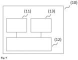
- Fig. 9 shows, by way of example and schematically, a computer system according to the present disclosure and that can be used for training the machine learning model and/or for using the trained machine learning model for prediction.
- peripherals refers to all devices that are connected to the computer and are used to control the computer and/or as input and output devices. Examples of these are monitors (screens), printers, scanners, mice, keyboards, drives, cameras, microphones, speakers, etc. Internal connections and expansion cards are also considered peripherals in computer technology.
- the Fig. 9 The computer system (1) shown comprises an input unit (10), a control and computing unit (20) and an output unit (30).
- the control and computing unit (20) serves to control the computer system (1), to coordinate the data flows between the units of the computer system (1) and to carry out calculations.
- Fig. 10 shows by way of example and schematically a further embodiment of the computer system according to the invention.
- the computer system (1) comprises a processing unit (21) which is connected to a memory (22).
- the processing unit (21) and the memory (22) form a control and calculation unit as described in Fig. 9 shown.
- the processing unit (21) may comprise one or more processors alone or in combination with one or more memories.
- the processing unit (21) may be ordinary computer hardware capable of processing information such as digital images, computer programs and/or other digital information.
- the processing unit (21) usually consists of an arrangement of electronic circuits, of some of which may be embodied as an integrated circuit or as multiple interconnected integrated circuits (an integrated circuit is sometimes referred to as a "chip").
- the processing unit (21) may be configured to execute computer programs that may be stored in a memory of the processing unit (21) or in the memory (22) of the same or another computer system.
- the processing unit (21) may also be connected to one or more interfaces (11, 12, 31, 32, 33) to display, transmit and/or receive information.
- the interfaces may comprise one or more communication interfaces (32, 33) and/or one or more user interfaces (11, 12, 31).
- the one or more communication interfaces may be configured to send and/or receive information, e.g. to and/or from an MRI scanner, a CT scanner, an ultrasound camera, other computer systems, networks, data storage or the like.
- the one or more communication interfaces may be configured to transmit and/or receive information via physical (wired) and/or wireless communication connections.
- the user interfaces may include a display (31).
- a display (31) may be configured to display information to a user. Suitable examples include a liquid crystal display (LCD), a light emitting diode display (LED), a plasma display panel (PDP), or the like.
- the user input interface(s) (11, 12) may be wired or wireless and may be configured to receive information from a user into the computer system (1), e.g. for processing, storage, and/or display. Suitable examples of user input interfaces include a microphone, an image or video capture device (e.g. a camera), a keyboard or keypad, a joystick, a touch-sensitive surface (separate from or integrated into a touchscreen), or the like.
- the user interfaces may include automatic identification and data capture (AIDC) technology for machine-readable information. These may include barcodes, radio frequency identification (RFID), magnetic stripe, optical character recognition (OCR), integrated circuit cards (ICC), and the like.
- the user interfaces may further include one or more interfaces for communicating with peripheral devices such as printers and the like.
- One or more computer programs (40) may be stored in the memory (22) and executed by the processing unit (21), which is thereby programmed to perform the functions described in this description.
- the retrieval, loading and execution of instructions of the computer program (40) may be carried out sequentially, so that one instruction is retrieved, loaded and executed at a time. However, the retrieval, loading and/or execution may also be carried out in parallel.
- the machine learning model according to the invention can also be stored in the memory (22).
- the system according to the invention can be designed as a laptop, notebook, netbook and/or tablet PC; it can also be a component of an MRI scanner, a CT scanner or an ultrasound diagnostic device.
Landscapes
- Engineering & Computer Science (AREA)
- Health & Medical Sciences (AREA)
- Medical Informatics (AREA)
- Public Health (AREA)
- General Health & Medical Sciences (AREA)
- Biomedical Technology (AREA)
- Epidemiology (AREA)
- Data Mining & Analysis (AREA)
- Primary Health Care (AREA)
- Databases & Information Systems (AREA)
- Pathology (AREA)
- Nuclear Medicine, Radiotherapy & Molecular Imaging (AREA)
- Radiology & Medical Imaging (AREA)
- Image Analysis (AREA)
- Magnetic Resonance Imaging Apparatus (AREA)
Claims (12)
- Procédé pour l'entraînement d'un modèle (MLM) d'apprentissage automatique pour générer des images radiologiques synthétiques sur la base d'images radiologiques mesurées, le procédé comprenant :- la réception et/ou la fourniture de données d'entraînement (TD), les données d'entraînement (TD), pour chaque objet d'examen d'une pluralité d'objets d'examen, comprenant un ensemble de données d'entrée et de données cibles,chaque ensemble comprenant∘ au moins une représentation d'entrée (R1, R2) d'une zone d'examen de l'objet d'examen dans un premier état en tant que données d'entrée, et∘ une représentation cible (TR) de la zone d'examen de l'objet d'examen dans un second état ainsi qu'une représentation cible transformée (TR T ) en tant que données cibles,la représentation cible transformée (TR T ) représentant au moins une partie de la zone d'examen de l'objet d'examen∘ dans le domaine fréquentiel si la représentation cible (TR) représente la zone d'examen de l'objet d'examen dans le domaine spatial, ou∘ dans le domaine spatial si la représentation cible (TR) représente la zone d'examen de l'objet d'examen dans le domaine fréquentiel,- l'entraînement d'un modèle (MLM) d'apprentissage automatique, le modèle (MLM) d'apprentissage automatique étant configuré pour générer, sur la base d'au moins une représentation d'entrée (R1, R2) et de paramètres de modèle (MP), une représentation synthétique (SR) de la zone d'examen de l'objet d'examen, ladite au moins une représentation d'entrée (R1, R2) représentant la zone d'examen pendant une première période avant et/ou après l'application d'une quantité d'un agent de contraste, et la représentation synthétique (SR) représentant la zone d'examen pendant une seconde période après l'application de la quantité de l'agent de contraste, la seconde période étant postérieure à la première période,
l'entraînement, pour chaque objet d'examen de la pluralité d'objets d'examen, comprenant :∘ la fourniture de ladite au moins une représentation d'entrée (R1, R2) au modèle (MLM) d'apprentissage automatique,∘ la réception d'une représentation synthétique (SR) de la zone d'examen de l'objet d'examen en provenance du modèle (MLM) d'apprentissage automatique,∘ la génération et/ou la réception d'une représentation synthétique transformée (SR T ) basée sur et/ou en relation avec la représentation synthétique (SR), la représentation synthétique transformée (SR T ) représentant au moins une partie de la zone d'examen de l'objet d'examen▪ dans le domaine fréquentiel si la représentation synthétique (SR) représente la zone d'examen de l'objet d'examen dans le domaine spatial, ou▪ dans le domaine spatial si la représentation synthétique (SR) représente la zone d'examen de l'objet d'examen dans le domaine fréquentiel,∘ la quantification des écarts i) entre au moins une partie de la représentation synthétique (SR) et au moins une partie de la représentation cible (TR) et ii) entre au moins une partie (SR T,P ) de la représentation synthétique transformée (SR T ) et au moins une partie (TR T,P ) de la représentation cible transformée (TR T ), au moyen d'une fonction d'erreur (L),∘ la modification de paramètres de modèle (MP) en vue de réduire les écarts,- la fourniture en sortie et/ou le stockage du modèle entraîné (MLMt) d'apprentissage automatique et/ou des paramètres de modèle (MP) et/ou la transmission du modèle entraîné (MLMt) d'apprentissage automatique et/ou des paramètres de modèle (MP) à un système d'ordinateur distinct. - Procédé selon la revendication 1,dans lequel la réception et/ou la fourniture de données d'entraînement (TD) comprend :- la génération d'une représentation cible transformée partielle (TR T,P ), la représentation cible transformée partielle (TR T,P ) étant réduite à une ou plusieurs parties de la représentation cible transformée (TR T ),la génération et/ou la réception d'une représentation synthétique transformée (SRT) basée sur et/ou en relation avec la représentation synthétique (SR) comprenant :- la génération d'une représentation synthétique transformée partielle (SRT,P), la représentation synthétique transformée partielle (SR T ) étant réduite à une partie ou plusieurs parties de la représentation synthétique transformée (SR T ),la quantification des écarts entre la représentation synthétique transformée (SR T ) et la représentation cible transformée (TR T ) comprenant :- la quantification des écarts entre la représentation synthétique transformée partielle (SR T,P ) et la représentation cible transformée partielle (TR T,P ).
- Procédé selon la revendication 1 ou 2,
dans lequel l'entraînement, pour chaque objet d'examen de la pluralité d'objets d'examen, comprend :∘ la fourniture de ladite au moins une représentation d'entrée (R1, R2) au modèle (MLM) d'apprentissage automatique,∘ la réception de la représentation synthétique (SR) et d'une première représentation synthétique transformée (SR T ) de la zone d'examen de l'objet d'examen en provenance du modèle (MLM) d'apprentissage automatique, la première représentation synthétique transformée (SR T ) représentant au moins une partie de la zone d'examen de l'objet d'examen▪ dans le domaine fréquentiel si la représentation synthétique (SR) représente la zone d'examen de l'objet d'examen dans le domaine spatial, ou▪ dans le domaine spatial si la représentation synthétique (SR) représente la zone d'examen de l'objet d'examen dans le domaine fréquentiel,∘ la génération d'une seconde représentation synthétique transformée (SR T*) sur la base de la représentation synthétique (SR) au moyen d'une transformation (T), la seconde représentation synthétique transformée (SR T*) représentant au moins une partie de la zone d'examen de l'objet d'examen▪ dans le domaine fréquentiel si la représentation synthétique (SR) représente la zone d'examen de l'objet d'examen dans le domaine spatial, ou▪ dans le domaine spatial si la représentation synthétique (SR) représente la zone d'examen de l'objet d'examen dans le domaine fréquentiel,- la quantification des écarts i) entre au moins une partie de la représentation synthétique (SR) et au moins une partie de la représentation cible (TR), ii) entre au moins une partie de la première représentation synthétique transformée (SR T ) et au moins une partie de la représentation cible transformée (TR*), et iii) entre au moins une partie de la première représentation synthétique transformée (SR T ) et au moins une partie de la seconde représentation synthétique transformée (SR T*) au moyen d'une fonction d'erreur (L),- la modification de paramètres de modèle (MP) en vue de réduire les écarts. - Procédé selon l'une quelconque des revendications 1 à 3,dans lequel le modèle (MLM) d'apprentissage automatique comprend un premier modèle (MLM1) d'apprentissage automatique et un second modèle (MLM2) d'apprentissage automatique,le premier modèle (MLM1) d'apprentissage automatique étant configuré pour générer, sur la base d'au moins une représentation d'entrée (R1) et de paramètres de modèle (MP1), une représentation synthétique (SR) de la zone d'examen de l'objet d'examen,le second modèle (MLM2) d'apprentissage automatique étant configuré pour reconstruire, sur la base de la représentation synthétique (SR) de la zone d'examen de l'objet d'examen, la représentation d'entrée (R1), l'entraînement, pour chaque objet d'examen de la pluralité d'objets d'examen, comprenant :∘ la génération d'une représentation d'entrée transformée (R2) sur la base de la représentation d'entrée (R1) au moyen d'une transformation (T), la représentation d'entrée transformée (R2) représentant au moins une partie de la zone d'examen de l'objet d'examen▪ dans le domaine fréquentiel si la représentation d'entrée (R1) représente la zone d'examen de l'objet d'examen dans le domaine spatial, ou▪ dans le domaine spatial si la représentation d'entrée (R1) représente la zone d'examen de l'objet d'examen dans le domaine fréquentiel,∘ l'envoi de ladite au moins une représentation d'entrée (R1) au premier modèle (MLM1) d'apprentissage automatique,∘ la réception d'une représentation synthétique (SR) de la zone d'examen de l'objet d'examen en provenance du premier modèle (MLM1) d'apprentissage automatique,∘ la génération et/ou la réception d'une représentation synthétique transformée (SR T ) basée sur et/ou en relation avec la représentation synthétique (SR), la représentation synthétique transformée (SR T ) représentant au moins une partie de la zone d'examen de l'objet d'examen▪ dans le domaine fréquentiel si la représentation synthétique (SR) représente la zone d'examen de l'objet d'examen dans le domaine spatial, ou▪ dans le domaine spatial si la représentation synthétique (SR) représente la zone d'examen de l'objet d'examen dans le domaine fréquentiel,∘ l'envoi de la représentation synthétique (SR) et/ou de la représentation synthétique transformée (SR T ) au second modèle (MLM2) d'apprentissage automatique,∘ la réception d'une représentation d'entrée prédite (R1*) en provenance du second modèle (MLM2) d'apprentissage automatique,∘ la génération et/ou la réception d'une représentation d'entrée prédite transformée (R2*) basée sur et/ou en relation avec la représentation d'entrée prédite (R1*), la représentation d'entrée prédite transformée (R2*) représentant au moins une partie de la zone d'examen de l'objet d'examen▪ dans le domaine fréquentiel si la représentation d'entrée prédite (R1*) représente la zone d'examen de l'objet d'examen dans le domaine spatial, ou▪ dans le domaine spatial si la représentation d'entrée prédite (R1*) représente la zone d'examen de l'objet d'examen dans le domaine fréquentiel,∘ la quantification des écarts i) entre au moins une partie de la représentation synthétique (SR) et au moins une partie de la représentation cible (TR), ii) entre au moins une partie de la représentation synthétique transformée (SR T ) et au moins une partie de la représentation cible transformée (TR T ), iii) entre au moins une partie de la représentation d'entrée (R1) et au moins une partie de la représentation d'entrée prédite (R1*) et iv) entre au moins une partie de la représentation d'entrée transformée (R2) et au moins une partie de la représentation d'entrée prédite transformée (R2*) au moyen d'une fonction d'erreur,∘ la modification de paramètres de modèle (MP1, MP2) en vue de réduire les écarts.
- Procédé selon l'une quelconque des revendications 1 à 4, dans lequel la zone d'examen est un foie ou une partie d'un foie d'un être humain.
- Procédé selon l'une quelconque des revendications 1 à 5, dans lequel chacune desdites au moins une représentation d'entrée (R1, R2) est une représentation de la zone d'examen dans le domaine spatial, la représentation cible (TR) est une représentation de la zone d'examen dans le domaine spatial et la représentation synthétique (SR) est une représentation de la zone d'examen dans le domaine spatial.
- Procédé selon l'une quelconque des revendications 2 à 5, dans lequel la représentation synthétique transformée partielle (SR T,P ) représente la zone d'examen dans le domaine fréquentiel, la représentation synthétique transformée partielle (SR T,P ) étant réduite à une plage de fréquences de la représentation synthétique transformée (SR T ), et des informations de contraste étant codées dans la plage de fréquences.
- Procédé selon l'une quelconque des revendications 2 à 5, dans lequel la représentation synthétique transformée partielle (SR T,P ) représente la zone d'examen dans le domaine fréquentiel, la représentation synthétique transformée partielle (SR T,P ) étant réduite à une plage de fréquences de la représentation synthétique transformée (SR T ), et des informations sur les structures fines étant codées dans la plage de fréquences.
- Procédé mis en œuvre par ordinateur pour la génération d'une représentation synthétique d'une zone d'examen d'un objet d'examen, le procédé comprenant :- la réception d'au moins une représentation d'entrée (R1,2*) de la zone d'examen de l'objet d'examen dans un premier état, ladite au moins une représentation d'entrée (R1,2*) représentant la zone d'examen pendant une première période avant et/ou après l'application d'une quantité d'un agent de contraste,- la fourniture d'un modèle entraîné (MLMt) d'apprentissage automatique,• le modèle entraîné (MLMt) d'apprentissage automatique ayant été entraîné à partir de données d'entraînement (TD) pour générer, sur la base d'au moins une représentation d'entrée (R1, R2) d'une zone d'examen d'un objet d'examen dans un premier état, une représentation synthétique (SR) de la zone d'examen dans un second état,• les données d'entraînement (TD) comprenant, pour chaque objet d'examen d'une pluralité d'objets d'examen, i) une représentation d'entrée (R1) de la zone d'examen, ii) une représentation cible (TR) et iii) une représentation cible transformée (TR T ),• la représentation cible transformée (TR T ) représentant au moins une partie de la zone d'examen de l'objet d'examen dans le domaine fréquentiel si la représentation cible (TR) représente la zone d'examen de l'objet d'examen dans le domaine spatial, ou dans le domaine spatial si la représentation cible (TR) représente la zone d'examen de l'objet d'examen dans le domaine fréquentiel,• le modèle (MLMt) d'apprentissage automatique ayant été entraîné, pour chaque objet d'examen, pour rendre minimaux les écarts entre i) au moins une partie de la représentation synthétique (SR) et au moins une partie de la représentation cible (TR) et ii) entre au moins une partie d'une représentation synthétique transformée (SR T ) et au moins une partie de la représentation cible transformée (TR T ),- la fourniture en entrée de ladite au moins une représentation d'entrée reçue (R1,2*) de la zone d'examen de l'objet d'examen au modèle entraîné (MLMt) d'apprentissage automatique,- la réception d'une représentation synthétique (SR*) de la zone d'examen de l'objet d'examen dans le second état en provenance du modèle (MLMt) d'apprentissage automatique, la représentation synthétique (SR*) représentant la zone d'examen pendant une seconde période après l'application de la quantité de l'agent de contraste, la seconde période étant postérieure à la première période,- la fourniture en sortie et/ou le stockage de la représentation synthétique (SR*) et/ou la transmission de la représentation synthétique (SR*) à un système d'ordinateur distinct.
- Procédé selon la revendication 9, dans lequel le modèle entraîné (MLMt) d'apprentissage automatique a été entraîné dans un procédé selon l'une quelconque des revendications 1 à 8.
- Système d'ordinateur (10) comprenant• une unité de réception (11),• une unité de commande et de calcul (12) et• une unité de sortie (13),- l'unité de commande et de calcul (12) étant configurée pour amener l'unité de réception (11) à recevoir au moins une représentation d'entrée (R1,2*) d'une zone d'examen d'un nouvel objet d'examen dans un premier état, ladite au moins une représentation d'entrée (R1,2*) représentant la zone d'examen pendant une première période avant et/ou après l'application d'une quantité d'un agent de contraste,- l'unité de commande et de calcul (12) étant configurée pour fournir en entrée la représentation d'entrée (R1,2*) reçue à un modèle entraîné (MLMt) d'apprentissage automatique,∘ le modèle entraîné (MLMt) d'apprentissage automatique ayant été entraîné à partir de données d'entraînement (TD) pour générer, sur la base d'au moins une représentation d'entrée (R1, R2) d'une zone d'examen d'un objet d'examen dans un premier état, une représentation synthétique (SR) de la zone d'examen dans un second état,∘ les données d'entraînement (TD) comprenant, pour chaque objet d'examen d'une pluralité d'objets d'examen, i) une représentation d'entrée (R1) de la zone d'examen, ii) une représentation cible (TR) et iii) une représentation cible transformée (TR T ),∘ la représentation cible transformée (TR T ) représentant au moins une partie de la zone d'examen de l'objet d'examen dans le domaine fréquentiel si la représentation cible (TR) représente la zone d'examen de l'objet d'examen dans le domaine spatial, ou dans le domaine spatial si la représentation cible (TR) représente la zone d'examen de l'objet d'examen dans le domaine fréquentiel,∘ le modèle (MLMt) d'apprentissage automatique ayant été entraîné, pour chaque objet d'examen, pour rendre minimaux les écarts entre i) au moins une partie de la représentation synthétique (SR) et au moins une partie de la représentation cible (TR) et ii) entre au moins une partie d'une représentation synthétique transformée (SR T ) et au moins une partie de la représentation cible transformée (TR T ),- l'unité de commande et de calcul (12) étant configurée pour recevoir, en provenance du modèle (MLMt) d'apprentissage automatique, une représentation synthétique (SR*) de la zone d'examen du nouvel objet d'examen dans le second état, la représentation synthétique (SR*) représentant la zone d'examen pendant une seconde période après l'application de la quantité de l'agent de contraste, la seconde période étant postérieure à la première période,- l'unité de commande et de calcul (12) étant configurée pour amener l'unité de sortie (13) à fournir en sortie et/ou à stocker la représentation synthétique (SR*) et/ou à la transmettre à un système d'ordinateur distinct.
- Produit programme d'ordinateur comprenant un programme d'ordinateur (40) qui peut être chargé dans une mémoire de travail (22) d'un système d'ordinateur (1) et qui, dans celui-ci, amène le système d'ordinateur (1) à mettre en œuvre les étapes suivantes :- la réception d'au moins une représentation d'entrée (R1,2*) de la zone d'examen de l'objet d'examen dans un premier état, ladite au moins une représentation d'entrée (R1,2*) représentant la zone d'examen pendant une première période avant et/ou après l'application d'une quantité d'un agent de contraste,- la fourniture d'un modèle entraîné (MLMt) d'apprentissage automatique,• le modèle entraîné (MLMt) d'apprentissage automatique ayant été entraîné à partir de données d'entraînement (TD) pour générer, sur la base d'au moins une représentation d'entrée (R1, R2) d'une zone d'examen d'un objet d'examen dans un premier état, une représentation synthétique (SR) de la zone d'examen dans un second état,• les données d'entraînement (TD) comprenant, pour chaque objet d'examen d'une pluralité d'objets d'examen, i) une représentation d'entrée (R1) de la zone d'examen, ii) une représentation cible (TR) et iii) une représentation cible transformée (TR T ),• la représentation cible transformée (TR T ) représentant au moins une partie de la zone d'examen de l'objet d'examen dans le domaine fréquentiel si la représentation cible (TR) représente la zone d'examen de l'objet d'examen dans le domaine spatial, ou dans le domaine spatial si la représentation cible (TR) représente la zone d'examen de l'objet d'examen dans le domaine fréquentiel,• le modèle (MLMt) d'apprentissage automatique ayant été entraîné, pour chaque objet d'examen, pour rendre minimaux les écarts entre i) au moins une partie de la représentation synthétique (SR) et au moins une partie de la représentation cible (TR) et ii) entre au moins une partie d'une représentation synthétique transformée (SR T ) et au moins une partie de la représentation cible transformée (TR T ),- la fourniture en entrée de ladite au moins une représentation d'entrée reçue (R1,2*) de la zone d'examen de l'objet d'examen dans le modèle entraîné (MLMt) d'apprentissage automatique,- la réception d'une représentation synthétique (SR*) de la zone d'examen de l'objet d'examen dans le second état en provenance du modèle (MLMt) d'apprentissage automatique, la représentation synthétique (SR*) représentant la zone d'examen pendant une seconde période après l'application de la quantité de l'agent de contraste, la seconde période étant postérieure à la première période,- la fourniture en sortie et/ou le stockage de la représentation synthétique (SR*) et/ou la transmission de la représentation synthétique (SR*) à un système d'ordinateur distinct.
Priority Applications (1)
| Application Number | Priority Date | Filing Date | Title |
|---|---|---|---|
| EP23163650.7A EP4336513B1 (fr) | 2022-08-30 | 2022-08-30 | Production d'enregistrements radiologiques synthétiques |
Applications Claiming Priority (2)
| Application Number | Priority Date | Filing Date | Title |
|---|---|---|---|
| EP23163650.7A EP4336513B1 (fr) | 2022-08-30 | 2022-08-30 | Production d'enregistrements radiologiques synthétiques |
| EP22192907.8A EP4332983B1 (fr) | 2022-08-30 | 2022-08-30 | Production d'enregistrements radiologiques synthétiques |
Related Parent Applications (2)
| Application Number | Title | Priority Date | Filing Date |
|---|---|---|---|
| EP22192907.8A Division-Into EP4332983B1 (fr) | 2022-08-30 | 2022-08-30 | Production d'enregistrements radiologiques synthétiques |
| EP22192907.8A Division EP4332983B1 (fr) | 2022-08-30 | 2022-08-30 | Production d'enregistrements radiologiques synthétiques |
Publications (2)
| Publication Number | Publication Date |
|---|---|
| EP4336513A1 EP4336513A1 (fr) | 2024-03-13 |
| EP4336513B1 true EP4336513B1 (fr) | 2024-12-18 |
Family
ID=83444873
Family Applications (2)
| Application Number | Title | Priority Date | Filing Date |
|---|---|---|---|
| EP23163650.7A Active EP4336513B1 (fr) | 2022-08-30 | 2022-08-30 | Production d'enregistrements radiologiques synthétiques |
| EP22192907.8A Active EP4332983B1 (fr) | 2022-08-30 | 2022-08-30 | Production d'enregistrements radiologiques synthétiques |
Family Applications After (1)
| Application Number | Title | Priority Date | Filing Date |
|---|---|---|---|
| EP22192907.8A Active EP4332983B1 (fr) | 2022-08-30 | 2022-08-30 | Production d'enregistrements radiologiques synthétiques |
Country Status (1)
| Country | Link |
|---|---|
| EP (2) | EP4336513B1 (fr) |
Family Cites Families (4)
| Publication number | Priority date | Publication date | Assignee | Title |
|---|---|---|---|---|
| US6039931A (en) | 1989-06-30 | 2000-03-21 | Schering Aktiengesellschaft | Derivatized DTPA complexes, pharmaceutical agents containing these compounds, their use, and processes for their production |
| BR112020007105A2 (pt) | 2017-10-09 | 2020-09-24 | The Board Of Trustees Of The Leland Stanford Junior University | método para treinar um dispositivo de diagnóstico por imagem para realizar uma imagem para diagnóstico médico com uma dose reduzida de agente de contraste |
| ES2955349T3 (es) | 2019-09-18 | 2023-11-30 | Bayer Ag | Predicción de imágenes MRI mediante un modelo de predicción entrenado por aprendizaje supervisado |
| CN115398555A (zh) | 2020-04-03 | 2022-11-25 | 拜耳公司 | 生成放射线图像 |
-
2022
- 2022-08-30 EP EP23163650.7A patent/EP4336513B1/fr active Active
- 2022-08-30 EP EP22192907.8A patent/EP4332983B1/fr active Active
Also Published As
| Publication number | Publication date |
|---|---|
| EP4332983B1 (fr) | 2025-03-05 |
| EP4336513A1 (fr) | 2024-03-13 |
| EP4332983A1 (fr) | 2024-03-06 |
Similar Documents
| Publication | Publication Date | Title |
|---|---|---|
| EP4143779B1 (fr) | Apprentissage automatique dans le domaine de la radiologie assistée par contraste | |
| WO2021197996A1 (fr) | Génération d'images radiologiques | |
| DE112016006137T5 (de) | Synthetische Darstellung einer Gefäßstruktur | |
| EP4483197B1 (fr) | Prédiction d'une représentation d'une zone d'examen d'un objet d'examen dans un état d'une séquence d'états | |
| EP4482393B1 (fr) | Prédiction d'une représentation d'une zone d'examen d'un objet d'examen après l'application de différentes quantités d'un agent de contraste | |
| EP4348573A1 (fr) | Apprentissage machine dans le domaine de la radiologie avec agent de contraste | |
| EP4581640B1 (fr) | Production d'enregistrements radiologiques synthétiques | |
| EP4154797A1 (fr) | Procédé de détermination d'un plan de coupe pertinent pour le diagnostic | |
| EP4336513B1 (fr) | Production d'enregistrements radiologiques synthétiques | |
| EP4332601B1 (fr) | Génération d'enregistrements radiologiques artificiels renforcés par un agent de contraste | |
| EP4475070B1 (fr) | Détection d'artéfacts dans des enregistrements médicaux synthétiques | |
| EP4584603B1 (fr) | Accélération d'examens irm du foie | |
| EP4581641B1 (fr) | Production d'enregistrements radiologiques synthétiques | |
| EP4485474B1 (fr) | Génération d'enregistrements radiologiques artificiels à contraste amélioré | |
| EP4475137B1 (fr) | Génération d'enregistrements radiologiques artificiels à contraste amélioré | |
| WO2024046833A1 (fr) | Génération d'images radiologiques synthétiques | |
| DE102009015116B4 (de) | Verfahren und Vorrichtung zur Registrierung von Bilddatensätzen und zur Reduktion von lagebedingten Grauwertschwankungen nebst zugehörigen Gegenständen | |
| EP4369285A1 (fr) | Génération d'enregistrements radiologiques artificiels renforcés par un agent de contraste | |
| EP4498324A1 (fr) | Détection d'artéfacts dans des images synthétiques | |
| WO2024083466A1 (fr) | Analyse automatisée d'images radiologiques |
Legal Events
| Date | Code | Title | Description |
|---|---|---|---|
| PUAI | Public reference made under article 153(3) epc to a published international application that has entered the european phase |
Free format text: ORIGINAL CODE: 0009012 |
|
| STAA | Information on the status of an ep patent application or granted ep patent |
Free format text: STATUS: THE APPLICATION HAS BEEN PUBLISHED |
|
| AC | Divisional application: reference to earlier application |
Ref document number: 4332983 Country of ref document: EP Kind code of ref document: P |
|
| AK | Designated contracting states |
Kind code of ref document: A1 Designated state(s): AL AT BE BG CH CY CZ DE DK EE ES FI FR GB GR HR HU IE IS IT LI LT LU LV MC MK MT NL NO PL PT RO RS SE SI SK SM TR |
|
| STAA | Information on the status of an ep patent application or granted ep patent |
Free format text: STATUS: REQUEST FOR EXAMINATION WAS MADE |
|
| 17P | Request for examination filed |
Effective date: 20240523 |
|
| GRAP | Despatch of communication of intention to grant a patent |
Free format text: ORIGINAL CODE: EPIDOSNIGR1 |
|
| STAA | Information on the status of an ep patent application or granted ep patent |
Free format text: STATUS: GRANT OF PATENT IS INTENDED |
|
| INTG | Intention to grant announced |
Effective date: 20240801 |
|
| RBV | Designated contracting states (corrected) |
Designated state(s): AL AT BE BG CH CY CZ DE DK EE ES FI FR GB GR HR HU IE IS IT LI LT LU LV MC MK MT NL NO PL PT RO RS SE SI SK SM TR |
|
| GRAS | Grant fee paid |
Free format text: ORIGINAL CODE: EPIDOSNIGR3 |
|
| GRAA | (expected) grant |
Free format text: ORIGINAL CODE: 0009210 |
|
| STAA | Information on the status of an ep patent application or granted ep patent |
Free format text: STATUS: THE PATENT HAS BEEN GRANTED |
|
| AC | Divisional application: reference to earlier application |
Ref document number: 4332983 Country of ref document: EP Kind code of ref document: P |
|
| AK | Designated contracting states |
Kind code of ref document: B1 Designated state(s): AL AT BE BG CH CY CZ DE DK EE ES FI FR GB GR HR HU IE IS IT LI LT LU LV MC MK MT NL NO PL PT RO RS SE SI SK SM TR |
|
| P01 | Opt-out of the competence of the unified patent court (upc) registered |
Free format text: CASE NUMBER: APP_61540/2024 Effective date: 20241118 |
|
| REG | Reference to a national code |
Ref country code: CH Ref legal event code: EP |
|
| REG | Reference to a national code |
Ref country code: DE Ref legal event code: R096 Ref document number: 502022002456 Country of ref document: DE |
|
| REG | Reference to a national code |
Ref country code: IE Ref legal event code: FG4D Free format text: LANGUAGE OF EP DOCUMENT: GERMAN |
|
| REG | Reference to a national code |
Ref country code: LT Ref legal event code: MG9D |
|
| PG25 | Lapsed in a contracting state [announced via postgrant information from national office to epo] |
Ref country code: HR Free format text: LAPSE BECAUSE OF FAILURE TO SUBMIT A TRANSLATION OF THE DESCRIPTION OR TO PAY THE FEE WITHIN THE PRESCRIBED TIME-LIMIT Effective date: 20241218 |
|
| PG25 | Lapsed in a contracting state [announced via postgrant information from national office to epo] |
Ref country code: FI Free format text: LAPSE BECAUSE OF FAILURE TO SUBMIT A TRANSLATION OF THE DESCRIPTION OR TO PAY THE FEE WITHIN THE PRESCRIBED TIME-LIMIT Effective date: 20241218 |
|
| PG25 | Lapsed in a contracting state [announced via postgrant information from national office to epo] |
Ref country code: BG Free format text: LAPSE BECAUSE OF FAILURE TO SUBMIT A TRANSLATION OF THE DESCRIPTION OR TO PAY THE FEE WITHIN THE PRESCRIBED TIME-LIMIT Effective date: 20241218 |
|
| PG25 | Lapsed in a contracting state [announced via postgrant information from national office to epo] |
Ref country code: NO Free format text: LAPSE BECAUSE OF FAILURE TO SUBMIT A TRANSLATION OF THE DESCRIPTION OR TO PAY THE FEE WITHIN THE PRESCRIBED TIME-LIMIT Effective date: 20250318 |
|
| REG | Reference to a national code |
Ref country code: NL Ref legal event code: MP Effective date: 20241218 |
|
| PG25 | Lapsed in a contracting state [announced via postgrant information from national office to epo] |
Ref country code: GR Free format text: LAPSE BECAUSE OF FAILURE TO SUBMIT A TRANSLATION OF THE DESCRIPTION OR TO PAY THE FEE WITHIN THE PRESCRIBED TIME-LIMIT Effective date: 20250319 Ref country code: LV Free format text: LAPSE BECAUSE OF FAILURE TO SUBMIT A TRANSLATION OF THE DESCRIPTION OR TO PAY THE FEE WITHIN THE PRESCRIBED TIME-LIMIT Effective date: 20241218 |
|
| PG25 | Lapsed in a contracting state [announced via postgrant information from national office to epo] |
Ref country code: RS Free format text: LAPSE BECAUSE OF FAILURE TO SUBMIT A TRANSLATION OF THE DESCRIPTION OR TO PAY THE FEE WITHIN THE PRESCRIBED TIME-LIMIT Effective date: 20250318 |
|
| PG25 | Lapsed in a contracting state [announced via postgrant information from national office to epo] |
Ref country code: NL Free format text: LAPSE BECAUSE OF FAILURE TO SUBMIT A TRANSLATION OF THE DESCRIPTION OR TO PAY THE FEE WITHIN THE PRESCRIBED TIME-LIMIT Effective date: 20241218 |
|
| PG25 | Lapsed in a contracting state [announced via postgrant information from national office to epo] |
Ref country code: SM Free format text: LAPSE BECAUSE OF FAILURE TO SUBMIT A TRANSLATION OF THE DESCRIPTION OR TO PAY THE FEE WITHIN THE PRESCRIBED TIME-LIMIT Effective date: 20241218 |
|
| PG25 | Lapsed in a contracting state [announced via postgrant information from national office to epo] |
Ref country code: PL Free format text: LAPSE BECAUSE OF FAILURE TO SUBMIT A TRANSLATION OF THE DESCRIPTION OR TO PAY THE FEE WITHIN THE PRESCRIBED TIME-LIMIT Effective date: 20241218 |
|
| PG25 | Lapsed in a contracting state [announced via postgrant information from national office to epo] |
Ref country code: ES Free format text: LAPSE BECAUSE OF FAILURE TO SUBMIT A TRANSLATION OF THE DESCRIPTION OR TO PAY THE FEE WITHIN THE PRESCRIBED TIME-LIMIT Effective date: 20241218 |
|
| PG25 | Lapsed in a contracting state [announced via postgrant information from national office to epo] |
Ref country code: IS Free format text: LAPSE BECAUSE OF FAILURE TO SUBMIT A TRANSLATION OF THE DESCRIPTION OR TO PAY THE FEE WITHIN THE PRESCRIBED TIME-LIMIT Effective date: 20250418 |
|
| PG25 | Lapsed in a contracting state [announced via postgrant information from national office to epo] |
Ref country code: PT Free format text: LAPSE BECAUSE OF FAILURE TO SUBMIT A TRANSLATION OF THE DESCRIPTION OR TO PAY THE FEE WITHIN THE PRESCRIBED TIME-LIMIT Effective date: 20250421 |
|
| PG25 | Lapsed in a contracting state [announced via postgrant information from national office to epo] |
Ref country code: EE Free format text: LAPSE BECAUSE OF FAILURE TO SUBMIT A TRANSLATION OF THE DESCRIPTION OR TO PAY THE FEE WITHIN THE PRESCRIBED TIME-LIMIT Effective date: 20241218 |
|
| PG25 | Lapsed in a contracting state [announced via postgrant information from national office to epo] |
Ref country code: RO Free format text: LAPSE BECAUSE OF FAILURE TO SUBMIT A TRANSLATION OF THE DESCRIPTION OR TO PAY THE FEE WITHIN THE PRESCRIBED TIME-LIMIT Effective date: 20241218 |
|
| PG25 | Lapsed in a contracting state [announced via postgrant information from national office to epo] |
Ref country code: SK Free format text: LAPSE BECAUSE OF FAILURE TO SUBMIT A TRANSLATION OF THE DESCRIPTION OR TO PAY THE FEE WITHIN THE PRESCRIBED TIME-LIMIT Effective date: 20241218 |
|
| PG25 | Lapsed in a contracting state [announced via postgrant information from national office to epo] |
Ref country code: CZ Free format text: LAPSE BECAUSE OF FAILURE TO SUBMIT A TRANSLATION OF THE DESCRIPTION OR TO PAY THE FEE WITHIN THE PRESCRIBED TIME-LIMIT Effective date: 20241218 |
|
| PG25 | Lapsed in a contracting state [announced via postgrant information from national office to epo] |
Ref country code: SE Free format text: LAPSE BECAUSE OF FAILURE TO SUBMIT A TRANSLATION OF THE DESCRIPTION OR TO PAY THE FEE WITHIN THE PRESCRIBED TIME-LIMIT Effective date: 20241218 |
|
| REG | Reference to a national code |
Ref country code: DE Ref legal event code: R097 Ref document number: 502022002456 Country of ref document: DE |
|
| PG25 | Lapsed in a contracting state [announced via postgrant information from national office to epo] |
Ref country code: DK Free format text: LAPSE BECAUSE OF FAILURE TO SUBMIT A TRANSLATION OF THE DESCRIPTION OR TO PAY THE FEE WITHIN THE PRESCRIBED TIME-LIMIT Effective date: 20241218 |
|
| PGFP | Annual fee paid to national office [announced via postgrant information from national office to epo] |
Ref country code: DE Payment date: 20250722 Year of fee payment: 4 |
|
| PGFP | Annual fee paid to national office [announced via postgrant information from national office to epo] |
Ref country code: IT Payment date: 20250901 Year of fee payment: 4 |
|
| PGFP | Annual fee paid to national office [announced via postgrant information from national office to epo] |
Ref country code: FR Payment date: 20250721 Year of fee payment: 4 Ref country code: AT Payment date: 20251020 Year of fee payment: 4 |
|
| PLBE | No opposition filed within time limit |
Free format text: ORIGINAL CODE: 0009261 |
|
| STAA | Information on the status of an ep patent application or granted ep patent |
Free format text: STATUS: NO OPPOSITION FILED WITHIN TIME LIMIT |
|
| REG | Reference to a national code |
Ref country code: CH Ref legal event code: L10 Free format text: ST27 STATUS EVENT CODE: U-0-0-L10-L00 (AS PROVIDED BY THE NATIONAL OFFICE) Effective date: 20251029 |
|
| 26N | No opposition filed |
Effective date: 20250919 |
|
| REG | Reference to a national code |
Ref country code: CH Ref legal event code: H13 Free format text: ST27 STATUS EVENT CODE: U-0-0-H10-H13 (AS PROVIDED BY THE NATIONAL OFFICE) Effective date: 20260324 |
|
| PG25 | Lapsed in a contracting state [announced via postgrant information from national office to epo] |
Ref country code: MC Free format text: LAPSE BECAUSE OF FAILURE TO SUBMIT A TRANSLATION OF THE DESCRIPTION OR TO PAY THE FEE WITHIN THE PRESCRIBED TIME-LIMIT Effective date: 20241218 |
|
| PG25 | Lapsed in a contracting state [announced via postgrant information from national office to epo] |
Ref country code: LU Free format text: LAPSE BECAUSE OF NON-PAYMENT OF DUE FEES Effective date: 20250830 |
|
| PG25 | Lapsed in a contracting state [announced via postgrant information from national office to epo] |
Ref country code: CH Free format text: LAPSE BECAUSE OF NON-PAYMENT OF DUE FEES Effective date: 20250831 |