EP4336521A1 - Verbindungsdraht und batteriepack damit - Google Patents
Verbindungsdraht und batteriepack damit Download PDFInfo
- Publication number
- EP4336521A1 EP4336521A1 EP22861730.4A EP22861730A EP4336521A1 EP 4336521 A1 EP4336521 A1 EP 4336521A1 EP 22861730 A EP22861730 A EP 22861730A EP 4336521 A1 EP4336521 A1 EP 4336521A1
- Authority
- EP
- European Patent Office
- Prior art keywords
- insulating member
- connection wire
- conductive
- wire according
- wound
- Prior art date
- Legal status (The legal status is an assumption and is not a legal conclusion. Google has not performed a legal analysis and makes no representation as to the accuracy of the status listed.)
- Pending
Links
Images






Classifications
-
- H—ELECTRICITY
- H01—ELECTRIC ELEMENTS
- H01M—PROCESSES OR MEANS, e.g. BATTERIES, FOR THE DIRECT CONVERSION OF CHEMICAL ENERGY INTO ELECTRICAL ENERGY
- H01M50/00—Constructional details or processes of manufacture of the non-active parts of electrochemical cells other than fuel cells, e.g. hybrid cells
- H01M50/20—Mountings; Secondary casings or frames; Racks, modules or packs; Suspension devices; Shock absorbers; Transport or carrying devices; Holders
- H01M50/298—Mountings; Secondary casings or frames; Racks, modules or packs; Suspension devices; Shock absorbers; Transport or carrying devices; Holders characterised by the wiring of battery packs
-
- H—ELECTRICITY
- H01—ELECTRIC ELEMENTS
- H01B—CABLES; CONDUCTORS; INSULATORS; SELECTION OF MATERIALS FOR THEIR CONDUCTIVE, INSULATING OR DIELECTRIC PROPERTIES
- H01B7/00—Insulated conductors or cables characterised by their form
- H01B7/02—Disposition of insulation
-
- H—ELECTRICITY
- H01—ELECTRIC ELEMENTS
- H01B—CABLES; CONDUCTORS; INSULATORS; SELECTION OF MATERIALS FOR THEIR CONDUCTIVE, INSULATING OR DIELECTRIC PROPERTIES
- H01B7/00—Insulated conductors or cables characterised by their form
- H01B7/04—Flexible cables, conductors, or cords, e.g. trailing cables
-
- H—ELECTRICITY
- H01—ELECTRIC ELEMENTS
- H01B—CABLES; CONDUCTORS; INSULATORS; SELECTION OF MATERIALS FOR THEIR CONDUCTIVE, INSULATING OR DIELECTRIC PROPERTIES
- H01B7/00—Insulated conductors or cables characterised by their form
- H01B7/08—Flat or ribbon cables
- H01B7/0846—Parallel wires, fixed upon a support layer
-
- H—ELECTRICITY
- H01—ELECTRIC ELEMENTS
- H01B—CABLES; CONDUCTORS; INSULATORS; SELECTION OF MATERIALS FOR THEIR CONDUCTIVE, INSULATING OR DIELECTRIC PROPERTIES
- H01B7/00—Insulated conductors or cables characterised by their form
- H01B7/17—Protection against damage caused by external factors, e.g. sheaths or armouring
- H01B7/18—Protection against damage caused by wear, mechanical force or pressure; Sheaths; Armouring
- H01B7/1805—Protections not provided for in groups H01B7/182 - H01B7/26
-
- H—ELECTRICITY
- H01—ELECTRIC ELEMENTS
- H01M—PROCESSES OR MEANS, e.g. BATTERIES, FOR THE DIRECT CONVERSION OF CHEMICAL ENERGY INTO ELECTRICAL ENERGY
- H01M10/00—Secondary cells; Manufacture thereof
- H01M10/42—Methods or arrangements for servicing or maintenance of secondary cells or secondary half-cells
-
- H—ELECTRICITY
- H01—ELECTRIC ELEMENTS
- H01M—PROCESSES OR MEANS, e.g. BATTERIES, FOR THE DIRECT CONVERSION OF CHEMICAL ENERGY INTO ELECTRICAL ENERGY
- H01M50/00—Constructional details or processes of manufacture of the non-active parts of electrochemical cells other than fuel cells, e.g. hybrid cells
- H01M50/20—Mountings; Secondary casings or frames; Racks, modules or packs; Suspension devices; Shock absorbers; Transport or carrying devices; Holders
- H01M50/204—Racks, modules or packs for multiple batteries or multiple cells
-
- H—ELECTRICITY
- H01—ELECTRIC ELEMENTS
- H01M—PROCESSES OR MEANS, e.g. BATTERIES, FOR THE DIRECT CONVERSION OF CHEMICAL ENERGY INTO ELECTRICAL ENERGY
- H01M50/00—Constructional details or processes of manufacture of the non-active parts of electrochemical cells other than fuel cells, e.g. hybrid cells
- H01M50/20—Mountings; Secondary casings or frames; Racks, modules or packs; Suspension devices; Shock absorbers; Transport or carrying devices; Holders
- H01M50/258—Modular batteries; Casings provided with means for assembling
-
- H—ELECTRICITY
- H01—ELECTRIC ELEMENTS
- H01M—PROCESSES OR MEANS, e.g. BATTERIES, FOR THE DIRECT CONVERSION OF CHEMICAL ENERGY INTO ELECTRICAL ENERGY
- H01M50/00—Constructional details or processes of manufacture of the non-active parts of electrochemical cells other than fuel cells, e.g. hybrid cells
- H01M50/50—Current conducting connections for cells or batteries
- H01M50/502—Interconnectors for connecting terminals of adjacent batteries; Interconnectors for connecting cells outside a battery casing
- H01M50/503—Interconnectors for connecting terminals of adjacent batteries; Interconnectors for connecting cells outside a battery casing characterised by the shape of the interconnectors
-
- H—ELECTRICITY
- H01—ELECTRIC ELEMENTS
- H01M—PROCESSES OR MEANS, e.g. BATTERIES, FOR THE DIRECT CONVERSION OF CHEMICAL ENERGY INTO ELECTRICAL ENERGY
- H01M50/00—Constructional details or processes of manufacture of the non-active parts of electrochemical cells other than fuel cells, e.g. hybrid cells
- H01M50/50—Current conducting connections for cells or batteries
- H01M50/502—Interconnectors for connecting terminals of adjacent batteries; Interconnectors for connecting cells outside a battery casing
- H01M50/521—Interconnectors for connecting terminals of adjacent batteries; Interconnectors for connecting cells outside a battery casing characterised by the material
- H01M50/522—Inorganic material
-
- H—ELECTRICITY
- H01—ELECTRIC ELEMENTS
- H01M—PROCESSES OR MEANS, e.g. BATTERIES, FOR THE DIRECT CONVERSION OF CHEMICAL ENERGY INTO ELECTRICAL ENERGY
- H01M50/00—Constructional details or processes of manufacture of the non-active parts of electrochemical cells other than fuel cells, e.g. hybrid cells
- H01M50/50—Current conducting connections for cells or batteries
- H01M50/502—Interconnectors for connecting terminals of adjacent batteries; Interconnectors for connecting cells outside a battery casing
- H01M50/521—Interconnectors for connecting terminals of adjacent batteries; Interconnectors for connecting cells outside a battery casing characterised by the material
- H01M50/526—Interconnectors for connecting terminals of adjacent batteries; Interconnectors for connecting cells outside a battery casing characterised by the material having a layered structure
-
- H—ELECTRICITY
- H01—ELECTRIC ELEMENTS
- H01M—PROCESSES OR MEANS, e.g. BATTERIES, FOR THE DIRECT CONVERSION OF CHEMICAL ENERGY INTO ELECTRICAL ENERGY
- H01M50/00—Constructional details or processes of manufacture of the non-active parts of electrochemical cells other than fuel cells, e.g. hybrid cells
- H01M50/50—Current conducting connections for cells or batteries
- H01M50/572—Means for preventing undesired use or discharge
- H01M50/574—Devices or arrangements for the interruption of current
- H01M50/583—Devices or arrangements for the interruption of current in response to current, e.g. fuses
-
- H—ELECTRICITY
- H01—ELECTRIC ELEMENTS
- H01M—PROCESSES OR MEANS, e.g. BATTERIES, FOR THE DIRECT CONVERSION OF CHEMICAL ENERGY INTO ELECTRICAL ENERGY
- H01M10/00—Secondary cells; Manufacture thereof
- H01M10/42—Methods or arrangements for servicing or maintenance of secondary cells or secondary half-cells
- H01M10/425—Structural combination with electronic components, e.g. electronic circuits integrated to the outside of the casing
- H01M2010/4271—Battery management systems including electronic circuits, e.g. control of current or voltage to keep battery in healthy state, cell balancing
-
- Y—GENERAL TAGGING OF NEW TECHNOLOGICAL DEVELOPMENTS; GENERAL TAGGING OF CROSS-SECTIONAL TECHNOLOGIES SPANNING OVER SEVERAL SECTIONS OF THE IPC; TECHNICAL SUBJECTS COVERED BY FORMER USPC CROSS-REFERENCE ART COLLECTIONS [XRACs] AND DIGESTS
- Y02—TECHNOLOGIES OR APPLICATIONS FOR MITIGATION OR ADAPTATION AGAINST CLIMATE CHANGE
- Y02E—REDUCTION OF GREENHOUSE GAS [GHG] EMISSIONS, RELATED TO ENERGY GENERATION, TRANSMISSION OR DISTRIBUTION
- Y02E60/00—Enabling technologies; Technologies with a potential or indirect contribution to GHG emissions mitigation
- Y02E60/10—Energy storage using batteries
Definitions
- connection wire and a battery pack including the same, and more particularly, to a connection wire for connecting a HV (high voltage) and a battery pack including the same.
- chargeable/dischargeable secondary batteries are used as a power source for an electric vehicle (EV), a hybrid electric vehicle (HEV), a plug-in hybrid electric vehicle (P-HEV) and the like, in an attempt to solve air pollution and the like caused by existing gasoline vehicles using fossil fuel. Therefore, the demand for development of the secondary battery is growing.
- EV electric vehicle
- HEV hybrid electric vehicle
- P-HEV plug-in hybrid electric vehicle
- the lithium secondary battery has come into the spotlight because it has advantages, for example, hardly exhibiting memory effects compared to nickel-based secondary batteries and thus being freely charged and discharged, and having very low self-discharge rate and high energy density.
- Such a lithium secondary battery mainly uses a lithium-based oxide and a carbonaceous material as a positive electrode active material and a negative electrode active material, respectively.
- the lithium secondary battery comprises an electrode assembly in which a positive electrode plate and a negative electrode plate, each being coated with the positive electrode active material and the negative electrode active material, are arranged with a separator being interposed between them, and a battery case which seals and houses the electrode assembly together with an electrolyte solution.
- the lithium secondary battery may be classified into a can-type secondary battery in which the electrode assembly is mounted in a metal can, and a pouch-type secondary battery in which the electrode assembly is mounted in a pouch of an aluminum laminate sheet, depending on the shape of the exterior material.
- a battery module in which a large number of battery cells are electrically connected is used.
- a large number of battery cells are connected to each other in series or parallel to form a cell assembly, thereby improving capacity and output.
- one or more battery modules can be mounted together with various control and protection systems such as a BDU(Battery Disconnect Unit), a BMS (battery management system) and a cooling system to form a battery pack.
- the HV connection is a connection serving as a power source for supplying power, and means a connection between battery cells or between battery modules.
- connection wire with increased flexibility so to be applicable to a limited space inside the battery pack, and a battery pack including the same.
- connection wire comprising: a plurality of conductive members; and an insulating member surrounding the conductive members, wherein the insulating member has a wound shape, and the conductive members are located on an inner surface of the insulating member.
- the conductive member may include a terminal part that is exposed by extending longer in one direction than the insulating member.
- the insulating member may have a wound shape, in a state in which the conductive members are sequentially arranged in the direction from a center side one end of the insulating member to an outside one end of the insulating member.
- a distance between the conductive member closest to the outside one end of the insulating member and the outside one end of the insulating member may be wider than a distance between the conductive member closest to the center side one end of the insulating member and the center side one end of the insulating member.
- the insulating member may be wound at least once or more to form an outer insulating part.
- the conductive member may be a flexible flat cable.
- the conductive member may include a conductor part and an insulating film surrounding the conductor part.
- the conductive member may be an electric conductor.
- the connection wire may further include a shielding circuit part.
- the shielding circuit part may be located on the inner surface of the wound insulating member, and based on the winding shape of the insulating member, the shielding circuit part may be located farther from the winding center than the conductive members.
- the insulating member may have a wound shape, in a state in which the shielding circuit part is spaced apart from the conductive member in the direction from a center side one end of the insulating member to an outside one end of the insulating member.
- the shielding circuit part may include a metal layer.
- connection wire may further include a short circuit prevention sheet.
- the short circuit prevention sheet may be located on the inner surface of the wound insulating member, and on the basis of the wound shape of the insulating member, the short circuit prevention sheet may be located farther from the winding center than the conductive members.
- the short circuit prevention sheet may include a ceramic sheet.
- the short circuit prevention sheet may include a MICA sheet.
- a battery pack comprising: the connection wire; battery modules; and a BDU module, wherein the connection wire electrically connects between the battery modules or between the battery module and the BDU module.
- connection wire is provided in the form of winding a plurality of conductive members around an insulating member, thereby being able to increasing the flexibility of the connection wire.
- an insulating member since an insulating member has a wound shape, it can be bent after locally compressing the pore inside the insulating member. Since the pore inside the insulating member can be compressed and bent as described above, a bent portion can be formed in the connection wire with a more reduced radius of curvature.
- planar when referred to as “planar”, it means when a target portion is viewed from the upper side, and when referred to as “cross-sectional”, it means when a target portion is viewed from the side of a cross section cut vertically.
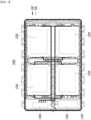
- Fig. 1 is a plan view showing a battery pack according to one embodiment of the present disclosure.
- the battery pack 1000 includes a connection wire 100, battery modules 1200 and a battery disconnect unit (BDU) module 1300.
- the connection wire 100 according to the present embodiment electrically connects between the battery modules 1200 or between the battery module 1200 and the BDU module 1300.
- a plurality of battery modules 1200 can be housed in a pack frame 1100, and electrical connection between the battery modules 1200 or between the battery module 1200 and the BDU module 1300 may be performed by the connection wire 100.
- the connection wire 100 according to the present embodiment can take charge of HV (high voltage) connection.
- the HV connection is a connection serving as a power source for supplying electric power, and means a connection between battery cells or between battery modules.
- the BDU module 1300 is a member for controlling electrical connection of the battery module 1200, and may cut off power between a power converter and the battery module 1200.
- the BDU module 1300 may secure the safety of the battery pack 1000 by cutting off the power of the battery pack 1000 if a condition occurs where the current exceeds the set range.
- the battery pack 1000 may include a BMS (battery management system) module 1400 for monitoring and controlling the operation of the battery module 1200 and a connection member 100' for connecting the battery module 1200 and the BMS module 1400.
- the connection member 100' ca take charge of LV (low voltage) connection.
- the LV connection means a sensing connection for sensing and controlling the voltage and temperature of the battery module 1200.
- a sensor or the like is arranged inside the battery module 1200, and real-time temperature information or voltage information of the battery module 1200 is transmitted to the BMS module 1400 via the connection member 100'. A real-time operating state of the battery module 1200 can be monitored and controlled via the BMS module 1400.
- the battery module 1200 according to the present embodiment will be described with reference to Figs. 2 and 3 .
- the battery module 1200 described below is an exemplary structure of a battery module including a plurality of battery cells 11, and various forms of battery modules including a plurality of battery cells can be applied.
- Fig. 2 is a perspective view showing a battery module included in the battery pack of Fig. 1 .
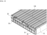
- Fig. 3 is a partial perspective view showing a state in which the module frame and the end plate are removed from the battery module of Fig. 2 .
- the battery module 1200 may include a battery cell stack 11A in which a plurality of battery cells 11 are stacked.
- the battery cell stack 11A is shown in Fig. 3 .
- the battery cell stack 11A may be housed in the module frame 30 and the end plate 40.
- the battery cell 11 may be a pouch-type battery cell.
- a pouch-type battery cell can be formed by housing an electrode assembly in a pouch case made a laminate sheet including a resin layer and a metal layer, and then fusing the outer periphery of the pouch case. These battery cells 11 can be formed into a rectangular sheet structure.
- the electrode lead 11L connected to the electrode assembly protrudes to the outside of the pouch case, wherein the electrode leads 11L of each battery cell 11 may be electrically connected to each other via the busbar 21. Meanwhile, at least one electrode lead 11L may be connected to the terminal busbar 22. A partial area of the terminal busbar 22 may be exposed to the outside of the battery module 1200 as shown in Fig. 2 .
- connection wire 100 is electrically connected to the terminal busbar 22, so that the above-mentioned HV connection can be performed. That is, the battery module 1200 may be electrically connected to the other battery module 1200 or BDU module 1300 via the connection wire 100 connected to the terminal busbar 22.
- connection wire according to one embodiment of the present disclosure will be described in detail with reference to Figs. 4 to 6 .
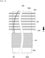
- Fig. 4 is a schematic diagram for explaining a process of manufacturing a connection wire according to one embodiment of the present disclosure.
- Fig. 5 is a perspective view showing a connection wire according to one embodiment of the present disclosure.
- Fig. 6 is a plan view of the connection wire of Fig. 5 as viewed along a direction A.
- the connection wire 100a includes a plurality of conductive members 200 and an insulating member 300 surrounding the conductive members 200.
- the insulating member 300 has a wound shape, and the conductive members 200 are located on the inner surface 300N of the insulating member 300.
- the insulating member 300 may be wound (W) into a round form.
- the connection wire 100a shown in Figs. 5 and 6 can be manufactured.
- the inner surface 300N of the insulating member 300 referred to herein may correspond to the one surface of the insulating member 300 on which the conductive members 200 are placed, that is, one surface in the direction in which the insulating member 300 is wound (W).
- connection wire 100a may have a shape so that the insulating member 300 is wound so as to wrap the conductive member 200, in a state in which the conductive members 200 are sequentially arranged in a direction d1 from the center side one end 300Ea of the insulating member 300 to the outside one end 300Eb of the insulating member 300.
- the center side one end 300Ea of the insulating member 300 is a portion that is first wound in the insulating member 300, which is a portion located at the winding center (WC, see Fig. 6 ) of the wound insulating member 300.
- the outside one end 300Eb of the insulating member 300 is a portion that is finally wound in the insulating member 300, which is the outermost portion of the wound insulating member 300.
- the conductive member 200 may include a terminal part 200T that is exposed by extending longer in one direction than the insulating member 300. That is, the conductive member 200 is formed longer than the insulating member 300 with respect to an extending direction of the connection wire 100a, and both ends of the conductive member 200 are exposed to the outside of the insulating member 300, so that a terminal part 200T can be provided.
- the method of forming the terminal part 200T is not particularly limited.
- the conductive member 200 can be formed longer than the insulating member 300 to naturally form the terminal part 200T.
- both ends of the insulating member 300 may be partially removed to expose the terminal part 200T.
- the terminal parts 200T of the conductive members can be joined to each other by welding or riveting.
- the terminal parts 200T are connected to the terminal busbar 22 of the above-mentioned battery module 1200, so that HV connection can be performed. This will be described again with reference to each embodiment of Figs. 7 and 8 .
- connection wire 100a has a wire shape extending long.
- the insulating member 300 may include an electrical insulating material.
- the insulating member 300 may include one or more materials selected from the group consisting of polypropylene (PP), polyethylene (PE), and polyvinyl chloride (PVC).
- the insulating member 300 may include a predetermined insulating adhesive layer.
- the insulating adhesive layer may include one or more resins selected from the group consisting of an epoxy resin, an acrylic resin, a melamine resin, a polyamide resin, and a polyimide resin.
- the outside one end 300Eb of the insulating member 300 may be attached and fixed by a method such as an adhesive or taping so that the wound insulating member 300 does not unwind. Alternatively, it can be fixed by applying a band tie to the outside of the insulating member 300. Alternatively, an additional insulating coating can be formed to prevent the insulating member 300 from unwinding. However, this is an exemplary method, and the method is not particularly limited as long as it can fix the outside one end 300Eb of the insulating member 300.
- a distance Gb between the conductive member 200b closest to the outside one end 300Eb of the insulating member 300 and the outside one end 300Eb of the insulating member 300 may be wider than a distance Ga between the conductive member 200a closest to the center side one end 300Ea of the insulating member 300 and the center side one end 300Ea of the insulating member 300. That is, in the connection wire 100a according to the present embodiment, the distance Gb between the conductive member 200b and the outside one end 300Eb of the insulating member 300 can be intentionally increased.
- the outermost region of the connection wire 100a may be configured such that the conductive member 200 is not interposed therein and only the insulating member 300 is additionally wound.
- the insulating member 300 may be wound at least once or more to form the outer insulating portion 300U. In this manner, in the present embodiment, by forming a region in which the insulating member 300 is additionally wound on the outside of the connection wire 100a, an insulating coating can be easily provided on the connection wire 100a.
- Fig. 7 is a partial perspective view showing a conductive member according to one embodiment of the present disclosure.
- the conductive member 200 may be a flexible flat cable (FFC). That is, the conductive member 200 according to the present embodiment may be a cable in which one or more conductor circuit lines are wrapped with an insulator on the same plane and sewn together.
- the conductive member 200 may include a conductor part 210 and an insulating film 220 surrounding the conductor part 210.
- the conductor part 210 may include an electrically conductive material.
- the conductor part 210 may include one or more metal materials selected from the group consisting of gold, silver, copper, lead, and aluminum. Such a conductor part 210 may be provided by a plurality of numbers.
- the plurality of conductor parts 210 may be arranged while being spaced apart by a predetermined distance in the width direction d2 of the conductive member 200.
- the width direction d2 of the conductive member 200 may be a direction orthogonal to a direction in which the conductive member 200 extends.
- the insulating film 220 is an electrically insulating material, and may include, for example, one or more materials selected from the group consisting of polypropylene (PP), polyethylene (PE), and polyvinyl chloride (PVC).
- PP polypropylene
- PE polyethylene
- PVC polyvinyl chloride
- the conductive member 200 is a flexible flat cable, and in a state where the conductor parts 210 are arranged in parallel at predetermined intervals, the conductive member can be manufactured by placing insulating films 220 above and below the conductor parts 210 and then laminating the insulating films 220.
- connection wire 100a may in the form of winding the insulating member 300 after the conductive members 200, which are flexible flat cables, are arranged on one surface of the insulating member 300.
- a portion of the insulating film 220 may be removed to expose a portion of the conductor part 210.
- An exposed portion of the conductor part 210 may be connected to the terminal busbar described above.
- Fig. 8 is a partial perspective view showing a conductive member according to another embodiment of the present disclosure.
- the conductive member 200' may be an electrical conductor. That is, the conductive member 200' according to the present embodiment may include a metal material having electrical conductivity.
- the conductive member 200' may be an electrical conductor including one or more metal materials selected from the group consisting of gold, silver, copper, lead, and aluminum.
- the connection wire 100a according to another embodiment of the present disclosure may be in the form of winding the insulating member 300 after a conductive member 200', which is an electrical conductor, is arranged on one surface of the insulating member 300.
- connection wire 100a will be described in comparison with the flexible busbar according to the comparative example of the present disclosure with reference to Figs. 9 and 10 .
- Fig. 9 is a partial perspective view showing a flexible busbar according to a comparative example of the present disclosure.
- the flexible busbar 10 used for HV connection may include conductor parts 10C and an insulation tube part 10T surrounding these conductor parts 10C.
- the insulation tube part 10T is configured to cover the plurality of conductor parts 10C. Even if a material with flexibility is applied, there is bound to be restrictions in realizing bent portions. In recent battery packs where utilization of internal space is important, the conventional flexible busbar 10 has limitations in adapting to the available space inside the battery pack.
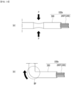
- Fig. 10 is a schematic diagram for explaining a process of forming a bent portion in a connection wire according to one embodiment of the present disclosure.
- connection wire 100a since the connection wire 100a according to the present embodiment has a shape in which the insulating member 300 is wound with the conductive members 200 placed on the inner surface 300N, a pore is formed between the conductive members 200 or inside the insulating member 300.
- a portion of the connection wire 100a may be locally compressed by using the pore inside the connection wire 100a.
- the bent portion BP may be formed in the connection wire 100a. That is, the shape of the cross section of the connection wire 100a according to the present embodiment can be locally changed using the internal pore, so that the radius of curvature of the bent portion BP can be reduced.
- the connection wire 100a can be strongly bent with a small radius of curvature, and thus, it is more suitable for application to a narrow space inside a battery pack.
- the insulating member 300 can be wound so that the conductive members 200 do not overlap each other.
- each of the conductive members 200 can be arranged so as to contact only the wound insulating member 300 and not to contact other conductive members 200. That is, a space can be secured between the conductive members 200, which can act as an advantage in terms of heat dissipation. Since the space between the conductive members 200 is advantageous for heat dissipation, it is possible to conduct electricity even if the cross-sectional area of the connection wire 100a is slightly reduced, which can be regarded as an advantageous factor for weight reduction and cost reduction.
- connection wire according to another embodiment of the present disclosure will be described in detail with reference to Figs. 11 to 13 .
- Fig. 11 is a schematic diagram for explaining a process of manufacturing a connection wire according to another embodiment of the present disclosure.
- Fig. 12 is a perspective view showing a connection wire according to another embodiment of the present disclosure.
- Fig. 13 is a plan view of the connection wire of Fig. 12 as viewed along a direction B.
- connection wire 100b includes a plurality of conductive members 200 and an insulating member 300 surrounding the conductive members 200.
- the insulating member 300 has a wound shape, and the conductive members 200 are located on the inner surface 300N of the insulating member 300. This is the same as the connection wire 100a described above.
- connection wire 100b may further include a shielding circuit part 400, wherein the shielding circuit part 400 may be located on the inner surface 300N of the wound insulating member 300.
- the insulating member 300 may be wound(W) into a round form. Thereby, it is possible to manufacture the connection wire 100b shown in Figs. 12 and 13 .
- the conductive members 200 are arranged closer to the center side one end 300Ea of the insulating member 300 than the shielding circuit parts 400, and the shielding circuit parts 400 may be arranged closer to the outside one end 300Eb of the insulating member 300 than the conductive members 200. That is, in the direction d1 from the center side one end 300Ea of the insulating member 300 to the outside one end 300Eb of the insulating member 300, the conductive member 200 can be sequentially arranged first, and then the shielding circuit parts 400 may be sequentially arranged.
- the shielding circuit part 400 may be located farther from the winding center WC than the conductive members 200 as shown in Figs. 12 and 13 . That is, the shielding circuit parts 400 may be located outside the conductive members 200 in the cross section of the connection wire 100b.
- the shielding circuit part 400 may include a metal layer.
- the shielding circuit part 400 may be a layered member including one or more metal materials selected from the group consisting of gold, silver, copper, lead, and aluminum.
- the shielding circuit part 400 is located outside the conductive member 200 and performs the function of preventing noise interference between the conductive member 200 functioning as a conducting circuit and the outside.
- the insulating member 300 may be wound with a predetermined distance between the shielding circuit parts 400 and the outside one end 300Eb of the insulating member 300.
- the portion of the insulation member 300 having the predetermined distance may be configured as an outer insulation part 300U at an outermost portion of the connection wire 100b.
- the shielding circuit part 400 together with the conductive member 200 is arranged on one surface of the insulating member 300, and then wound together, so that a shielding circuit part 400 can be provided on the connection wire 100b. That is, when winding the insulating member 300 without a separate additional process, it has an advantage that the shielding member can be easily provided by simply adding the shielding circuit part 400.
- connection wire 100b may have a shape in which the insulating member 300 is wound in a state in which the shielding circuit part 400 is spaced apart from the conductive member 200 in the direction d1 from the center side one end 300Ea of the insulating member 300 to the outside one end 300Eb of the insulating member 300. That is, when the insulating member 300 is wound, the shielding circuit part 400 may be located so as to be spaced apart from the conductive member 200 by a predetermined distance.
- the portion of the insulating member 300 corresponding to the distance between the conductive member 200 and the shielding circuit part 400 may be composed of an intermediate insulation part 300M that electrically insulates the conductive members 200 and the shielding circuit part 400.
- connection wire 100b adjusts the distance between the conductive member 200 on the insulating member 300 and the shielding circuit part 400 before winding, and has the advantage of being able to easily provide an insulating layer between the conductive member 200 and the shielding circuit part 400.
- Figs. 11 to 13 show forms in which a plurality of shielding circuit parts 400 are arranged at regular intervals, but a form in which a plate-shaped single shielding circuit part 400 is wound together with the insulating member 300 is also possible.
- connection wire according to another embodiment of the present disclosure will be described in detail with reference to Figs. 14 to 16 .
- Fig 14 is a schematic diagram for explaining a process of manufacturing a connection wire according to another embodiment of the present disclosure.
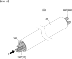
- Fig. 15 is a perspective view showing a connection wire according to another embodiment of the present disclosure.
- Fig. 16 is a plan view of the connection wire of Fig. 15 as viewed along a direction C.
- connection wire 100c includes a plurality of conductive members 200 and an insulating member 300 surrounding the conductive members 200.
- the insulating member 300 has a wound shape, and the conductive members 200 are located on the inner surface 300N of the insulating member 300. This is the same as the connection wires 100a and 100b described above.
- connection wire 100c may further include a short circuit prevention sheet 500, wherein the short circuit prevention sheet 500 may be located on the inner surface 300N of the wound insulating member 300.
- the insulating member 300 may be wound(W) into a round form. Thereby, it is possible to manufacture the connection wire 100c shown in Figs. 15 and 16 .
- the conductive members 200 are arranged closer to the center side one end 300Ea of the insulating member 300 than the short circuit prevention sheet 500, and the short circuit prevention sheet 500 may be arranged closer to the outside one end 300Eb of the insulating member 300 than the conductive members 200. That is, in the direction d1 from the center side one end 300Ea of the insulating member 300 to the outside one end 300Eb of the insulating member 300, the conductive members 200 may be sequentially arranged first, and then the short circuit prevention sheet 500 may be arranged.
- the short circuit prevention sheet 500 may be located farther from the winding center WC than the conductive members 200 as shown in Figs. 15 and 16 . That is, the short circuit prevention sheet 500 may be located outside the conductive members 200 in the cross-section of the connection wire 100c.
- the short circuit prevention sheet 500 may include a ceramic sheet. More specifically, the short circuit prevention sheet 500 may include a MICA sheet. That is, the short circuit prevention sheet may include a silicate-containing inorganic sheet.
- the battery pack according to the present embodiment When the battery pack according to the present embodiment is applied to a vehicle or the like, it is frequently exposed to direct sunlight and may be placed under high temperature conditions, for example, in summer or in a desert.
- a thermal runaway phenomenon generated in one battery module is easily propagated to adjacent battery modules, which may eventually lead to ignition or explosion of the battery pack itself.
- One example of a thermal runaway phenomenon is as follows. Physical, thermal, and electrical damage to the battery cell 11, including overcharging, may occur, and the internal pressure of the battery cell 11 may increase. When the fusion strength limit value of the pouch-type cell case of the battery cell 11 is exceeded, high-temperature heat, venting gas, and the like generated from the battery cell 11 may be ejected to the outside of the battery cell 11 .
- the short circuit prevention sheet 500 together with the conductive member 200 is arranged on one surface of the insulating member 300, and then wound together, so that a layer for short-circuit prevention can be provided on the connection wire 100c.
- the short circuit prevention sheet 500 including the ceramic sheet does not melt and can maintain its shape. Thereby, it is possible to prevent the conductor such as the internal conductive member 200 from contacting the external mechanism and causing a short circuit. In other words, in a high-temperature environment, additional hazardous situations can be prevented from occurring.
- connection wire 100c according to the present embodiment has the advantage that a layer for preventing thermal diffusion can be easily provided by simply adding the short circuit prevention sheet 500 when the insulating member 300 is wound without a separate additional process.
- a short circuit prevention sheet 500 such as a MICA sheet
- connection wire 100c according to the present embodiment can easily add a short circuit prevention sheet 500, thereby being able to prevent short circuits in the event of thermal runaway and ensure excellent stability.
- the battery pack according to the present embodiment described above can be applied to various devices. Specifically, it can be applied to vehicle means such as an electric bike, an electric vehicle, and a hybrid electric vehicle, or ESS (Energy Storage System), but is not limited thereto and can be applied to various devices capable of using a secondary battery.
- vehicle means such as an electric bike, an electric vehicle, and a hybrid electric vehicle, or ESS (Energy Storage System), but is not limited thereto and can be applied to various devices capable of using a secondary battery.
- ESS Electronicgy Storage System
Landscapes
- Chemical & Material Sciences (AREA)
- Chemical Kinetics & Catalysis (AREA)
- Electrochemistry (AREA)
- General Chemical & Material Sciences (AREA)
- Inorganic Chemistry (AREA)
- Engineering & Computer Science (AREA)
- Manufacturing & Machinery (AREA)
- Connection Of Batteries Or Terminals (AREA)
- Details Of Indoor Wiring (AREA)
- Battery Mounting, Suspending (AREA)
Applications Claiming Priority (2)
| Application Number | Priority Date | Filing Date | Title |
|---|---|---|---|
| KR1020210112603A KR102895043B1 (ko) | 2021-08-25 | 2021-08-25 | 연결 와이어 및 이를 포함하는 전지팩 |
| PCT/KR2022/012719 WO2023027522A1 (ko) | 2021-08-25 | 2022-08-25 | 연결 와이어 및 이를 포함하는 전지팩 |
Publications (2)
| Publication Number | Publication Date |
|---|---|
| EP4336521A1 true EP4336521A1 (de) | 2024-03-13 |
| EP4336521A4 EP4336521A4 (de) | 2024-10-09 |
Family
ID=85321921
Family Applications (1)
| Application Number | Title | Priority Date | Filing Date |
|---|---|---|---|
| EP22861730.4A Pending EP4336521A4 (de) | 2021-08-25 | 2022-08-25 | Verbindungsdraht und batteriepack damit |
Country Status (6)
| Country | Link |
|---|---|
| US (1) | US20240313331A1 (de) |
| EP (1) | EP4336521A4 (de) |
| JP (1) | JP7799939B2 (de) |
| KR (1) | KR102895043B1 (de) |
| CN (1) | CN117597746A (de) |
| WO (1) | WO2023027522A1 (de) |
Cited By (1)
| Publication number | Priority date | Publication date | Assignee | Title |
|---|---|---|---|---|
| EP4672406A1 (de) * | 2024-06-24 | 2025-12-31 | Elsa Solutions S.p.A. | Modulare feststoffbatterie und entsprechendes system modularer batterien |
Families Citing this family (3)
| Publication number | Priority date | Publication date | Assignee | Title |
|---|---|---|---|---|
| KR20240166720A (ko) | 2023-05-18 | 2024-11-26 | 주식회사 엘지에너지솔루션 | 배터리 팩 |
| KR20250006460A (ko) * | 2023-07-04 | 2025-01-13 | 주식회사 엘지에너지솔루션 | 버스바 조립체 및 이를 포함하는 전지 팩 |
| EP4734220A1 (de) * | 2024-10-28 | 2026-04-29 | Eve Energy Co., Ltd. | Batteriepack und fahrzeug |
Family Cites Families (13)
| Publication number | Priority date | Publication date | Assignee | Title |
|---|---|---|---|---|
| GB824615A (en) * | 1957-03-26 | 1959-12-02 | Standard Telephones Cables Ltd | Electrical cables and the manufacture thereof |
| JPS58100311A (ja) * | 1981-12-09 | 1983-06-15 | 株式会社日立製作所 | 多芯ケ−ブル |
| JPH05274924A (ja) * | 1992-03-25 | 1993-10-22 | Hitachi Cable Ltd | 地中送電用ケーブル |
| JP3316778B2 (ja) * | 1995-01-30 | 2002-08-19 | 矢崎総業株式会社 | シート電線の放熱構造および集束方法 |
| JPH0997520A (ja) * | 1995-09-29 | 1997-04-08 | Fujitsu Takamizawa Component Kk | 多芯ケーブル及びその製造方法 |
| JP4704588B2 (ja) * | 2001-03-16 | 2011-06-15 | 矢崎総業株式会社 | 導体薄膜シート及びシールドハーネス |
| EP1551037A1 (de) * | 2004-01-05 | 2005-07-06 | Alcan Technology & Management Ltd. | Flexibler Träger mit elektrisch leitfähiger Struktur |
| JP4883051B2 (ja) * | 2008-06-19 | 2012-02-22 | トヨタ自動車株式会社 | ワイヤーハーネス |
| EP2518736A1 (de) * | 2011-04-29 | 2012-10-31 | Tyco Electronics Nederland B.V. | Kabelanordnung mit einem flexiblen Träger aus einem Textilmaterial |
| KR101984903B1 (ko) * | 2018-02-02 | 2019-05-31 | (주)케이제이나노텍 | 판상의 외부 피복재를 이용한 케이블 덕트 제조 공법 |
| KR102705400B1 (ko) * | 2019-08-07 | 2024-09-12 | 주식회사 엘지에너지솔루션 | 자동차용 언더 바디 |
| KR102848070B1 (ko) * | 2020-01-07 | 2025-08-19 | 주식회사 엘지에너지솔루션 | Hv 와이어 어셈블리를 포함하는 배터리 팩 및 상기 배터리 팩의 제조 방법 |
| CN112562892A (zh) * | 2020-12-18 | 2021-03-26 | 长春捷翼汽车零部件有限公司 | 扁带式导电线体及扁带式线束 |
-
2021
- 2021-08-25 KR KR1020210112603A patent/KR102895043B1/ko active Active
-
2022
- 2022-08-25 CN CN202280045384.1A patent/CN117597746A/zh active Pending
- 2022-08-25 US US18/575,999 patent/US20240313331A1/en active Pending
- 2022-08-25 EP EP22861730.4A patent/EP4336521A4/de active Pending
- 2022-08-25 WO PCT/KR2022/012719 patent/WO2023027522A1/ko not_active Ceased
- 2022-08-25 JP JP2023574486A patent/JP7799939B2/ja active Active
Cited By (1)
| Publication number | Priority date | Publication date | Assignee | Title |
|---|---|---|---|---|
| EP4672406A1 (de) * | 2024-06-24 | 2025-12-31 | Elsa Solutions S.p.A. | Modulare feststoffbatterie und entsprechendes system modularer batterien |
Also Published As
| Publication number | Publication date |
|---|---|
| KR20230030414A (ko) | 2023-03-06 |
| KR102895043B1 (ko) | 2025-12-02 |
| CN117597746A (zh) | 2024-02-23 |
| EP4336521A4 (de) | 2024-10-09 |
| JP2024529224A (ja) | 2024-08-06 |
| JP7799939B2 (ja) | 2026-01-16 |
| WO2023027522A1 (ko) | 2023-03-02 |
| US20240313331A1 (en) | 2024-09-19 |
Similar Documents
| Publication | Publication Date | Title |
|---|---|---|
| EP4336521A1 (de) | Verbindungsdraht und batteriepack damit | |
| EP4170792A1 (de) | Batteriemodul und batteriepack damit | |
| US20240063484A1 (en) | Battery module and battery pack including the same | |
| EP4184706B1 (de) | Batteriemodul, batteriepack damit und herstellungsverfahren dafür | |
| EP4002570A1 (de) | Batteriemodul und dieses umfassendes batteriepack | |
| EP3664191A1 (de) | Elektrodenanordnung mit einem kunststoffelement, das auf ein verbindungsteil eines elektrodenlaschenträgers aufgebracht ist, und sekundärbatterie damit | |
| US20230069153A1 (en) | Battery Module, Battery Pack Including The Same And Manufacturing Method Of The Same | |
| EP4250449A1 (de) | Beutelartige batteriezelle mit verbesserter sicherheit und batteriemodul damit | |
| US20240030531A1 (en) | Battery module and battery pack including the same | |
| EP4648212A2 (de) | Batteriemodul, batteriepack damit und herstellungsverfahren dafür | |
| EP4531192A1 (de) | Sammelschienenanordnung und batteriepack damit | |
| EP4181275A1 (de) | Batteriemodul und batteriepack damit | |
| US12381288B2 (en) | Busbar module and method of manufacturing the same | |
| EP4181292A1 (de) | Batteriemodul und batteriepack damit | |
| US20230318078A1 (en) | Battery module and battery pack including the same | |
| KR20200099391A (ko) | 이차 전지 및 전지 모듈 | |
| US20260024883A1 (en) | Busbar assembly and battery pack including the same | |
| KR20230049453A (ko) | 이차 전지 및 이를 포함하는 전지 모듈 | |
| EP4250463B1 (de) | Batteriemodul und batteriepack damit | |
| EP4531196A1 (de) | Sammelschienenanordnung und batteriepack damit | |
| US12394872B2 (en) | Battery module and battery pack including the same | |
| KR20250058590A (ko) | 버스바 조립체 및 이를 포함하는 전지 팩 | |
| KR20250164905A (ko) | 버스바 조립체 및 이를 포함하는 전지 팩 |
Legal Events
| Date | Code | Title | Description |
|---|---|---|---|
| STAA | Information on the status of an ep patent application or granted ep patent |
Free format text: STATUS: THE INTERNATIONAL PUBLICATION HAS BEEN MADE |
|
| PUAI | Public reference made under article 153(3) epc to a published international application that has entered the european phase |
Free format text: ORIGINAL CODE: 0009012 |
|
| STAA | Information on the status of an ep patent application or granted ep patent |
Free format text: STATUS: REQUEST FOR EXAMINATION WAS MADE |
|
| 17P | Request for examination filed |
Effective date: 20231207 |
|
| AK | Designated contracting states |
Kind code of ref document: A1 Designated state(s): AL AT BE BG CH CY CZ DE DK EE ES FI FR GB GR HR HU IE IS IT LI LT LU LV MC MK MT NL NO PL PT RO RS SE SI SK SM TR |
|
| A4 | Supplementary search report drawn up and despatched |
Effective date: 20240906 |
|
| RIC1 | Information provided on ipc code assigned before grant |
Ipc: H01B 7/08 20060101ALI20240902BHEP Ipc: H01M 10/42 20060101ALI20240902BHEP Ipc: H01B 7/04 20060101ALI20240902BHEP Ipc: H01M 50/298 20210101ALI20240902BHEP Ipc: H01B 7/02 20060101AFI20240902BHEP |
|
| DAV | Request for validation of the european patent (deleted) | ||
| DAX | Request for extension of the european patent (deleted) | ||
| STAA | Information on the status of an ep patent application or granted ep patent |
Free format text: STATUS: EXAMINATION IS IN PROGRESS |
|
| 17Q | First examination report despatched |
Effective date: 20250409 |
|
| GRAP | Despatch of communication of intention to grant a patent |
Free format text: ORIGINAL CODE: EPIDOSNIGR1 |
|
| STAA | Information on the status of an ep patent application or granted ep patent |
Free format text: STATUS: GRANT OF PATENT IS INTENDED |
|
| INTG | Intention to grant announced |
Effective date: 20260120 |