EP4336669A2 - Dispositif de raccordement pour un appareil de terrain ainsi qu'appareil de terrain doté d'un tel dispositif de raccordement - Google Patents
Dispositif de raccordement pour un appareil de terrain ainsi qu'appareil de terrain doté d'un tel dispositif de raccordement Download PDFInfo
- Publication number
- EP4336669A2 EP4336669A2 EP24153687.9A EP24153687A EP4336669A2 EP 4336669 A2 EP4336669 A2 EP 4336669A2 EP 24153687 A EP24153687 A EP 24153687A EP 4336669 A2 EP4336669 A2 EP 4336669A2
- Authority
- EP
- European Patent Office
- Prior art keywords
- connector part
- cover flap
- contact
- end position
- contact area
- Prior art date
- Legal status (The legal status is an assumption and is not a legal conclusion. Google has not performed a legal analysis and makes no representation as to the accuracy of the status listed.)
- Pending
Links
Images


Classifications
-
- H—ELECTRICITY
- H01—ELECTRIC ELEMENTS
- H01R—ELECTRICALLY-CONDUCTIVE CONNECTIONS; STRUCTURAL ASSOCIATIONS OF A PLURALITY OF MUTUALLY-INSULATED ELECTRICAL CONNECTING ELEMENTS; COUPLING DEVICES; CURRENT COLLECTORS
- H01R13/00—Details of coupling devices of the kinds covered by groups H01R12/70 or H01R24/00 - H01R33/00
- H01R13/02—Contact members
- H01R13/10—Sockets for co-operation with pins or blades
- H01R13/11—Resilient sockets
- H01R13/111—Resilient sockets co-operating with pins having a circular transverse section
-
- H—ELECTRICITY
- H01—ELECTRIC ELEMENTS
- H01R—ELECTRICALLY-CONDUCTIVE CONNECTIONS; STRUCTURAL ASSOCIATIONS OF A PLURALITY OF MUTUALLY-INSULATED ELECTRICAL CONNECTING ELEMENTS; COUPLING DEVICES; CURRENT COLLECTORS
- H01R13/00—Details of coupling devices of the kinds covered by groups H01R12/70 or H01R24/00 - H01R33/00
- H01R13/44—Means for preventing access to live contacts
- H01R13/447—Shutter or cover plate
-
- G—PHYSICS
- G01—MEASURING; TESTING
- G01F—MEASURING VOLUME, VOLUME FLOW, MASS FLOW OR LIQUID LEVEL; METERING BY VOLUME
- G01F15/00—Details of, or accessories for, apparatus of groups G01F1/00 - G01F13/00 insofar as such details or appliances are not adapted to particular types of such apparatus
- G01F15/06—Indicating or recording devices
- G01F15/061—Indicating or recording devices for remote indication
- G01F15/063—Indicating or recording devices for remote indication using electrical means
-
- G—PHYSICS
- G08—SIGNALLING
- G08C—TRANSMISSION SYSTEMS FOR MEASURED VALUES, CONTROL OR SIMILAR SIGNALS
- G08C19/00—Electric signal transmission systems
-
- H—ELECTRICITY
- H01—ELECTRIC ELEMENTS
- H01R—ELECTRICALLY-CONDUCTIVE CONNECTIONS; STRUCTURAL ASSOCIATIONS OF A PLURALITY OF MUTUALLY-INSULATED ELECTRICAL CONNECTING ELEMENTS; COUPLING DEVICES; CURRENT COLLECTORS
- H01R13/00—Details of coupling devices of the kinds covered by groups H01R12/70 or H01R24/00 - H01R33/00
- H01R13/46—Bases; Cases
- H01R13/52—Dustproof, splashproof, drip-proof, waterproof, or flameproof cases
- H01R13/5213—Covers
-
- H—ELECTRICITY
- H01—ELECTRIC ELEMENTS
- H01R—ELECTRICALLY-CONDUCTIVE CONNECTIONS; STRUCTURAL ASSOCIATIONS OF A PLURALITY OF MUTUALLY-INSULATED ELECTRICAL CONNECTING ELEMENTS; COUPLING DEVICES; CURRENT COLLECTORS
- H01R13/00—Details of coupling devices of the kinds covered by groups H01R12/70 or H01R24/00 - H01R33/00
- H01R13/62—Means for facilitating engagement or disengagement of coupling parts or for holding them in engagement
- H01R13/639—Additional means for holding or locking coupling parts together, after engagement, e.g. separate keylock, retainer strap
-
- H—ELECTRICITY
- H01—ELECTRIC ELEMENTS
- H01R—ELECTRICALLY-CONDUCTIVE CONNECTIONS; STRUCTURAL ASSOCIATIONS OF A PLURALITY OF MUTUALLY-INSULATED ELECTRICAL CONNECTING ELEMENTS; COUPLING DEVICES; CURRENT COLLECTORS
- H01R43/00—Apparatus or processes specially adapted for manufacturing, assembling, maintaining, or repairing of line connectors or current collectors or for joining electric conductors
- H01R43/26—Apparatus or processes specially adapted for manufacturing, assembling, maintaining, or repairing of line connectors or current collectors or for joining electric conductors for engaging or disengaging the two parts of a coupling device
-
- G—PHYSICS
- G01—MEASURING; TESTING
- G01R—MEASURING ELECTRIC VARIABLES; MEASURING MAGNETIC VARIABLES
- G01R1/00—Details of instruments or arrangements of the types included in groups G01R5/00 - G01R13/00 and G01R31/00
- G01R1/02—General constructional details
- G01R1/04—Housings; Supporting members; Arrangements of terminals
- G01R1/0408—Test fixtures or contact fields; Connectors or connecting adaptors; Test clips; Test sockets
- G01R1/0416—Connectors, terminals
-
- G—PHYSICS
- G08—SIGNALLING
- G08C—TRANSMISSION SYSTEMS FOR MEASURED VALUES, CONTROL OR SIMILAR SIGNALS
- G08C2200/00—Transmission systems for measured values, control or similar signals
-
- H—ELECTRICITY
- H01—ELECTRIC ELEMENTS
- H01R—ELECTRICALLY-CONDUCTIVE CONNECTIONS; STRUCTURAL ASSOCIATIONS OF A PLURALITY OF MUTUALLY-INSULATED ELECTRICAL CONNECTING ELEMENTS; COUPLING DEVICES; CURRENT COLLECTORS
- H01R13/00—Details of coupling devices of the kinds covered by groups H01R12/70 or H01R24/00 - H01R33/00
- H01R13/46—Bases; Cases
- H01R13/533—Bases, cases made for use in extreme conditions, e.g. high temperature, radiation, vibration, corrosive environment, pressure
-
- H—ELECTRICITY
- H01—ELECTRIC ELEMENTS
- H01R—ELECTRICALLY-CONDUCTIVE CONNECTIONS; STRUCTURAL ASSOCIATIONS OF A PLURALITY OF MUTUALLY-INSULATED ELECTRICAL CONNECTING ELEMENTS; COUPLING DEVICES; CURRENT COLLECTORS
- H01R2105/00—Three poles
-
- H—ELECTRICITY
- H01—ELECTRIC ELEMENTS
- H01R—ELECTRICALLY-CONDUCTIVE CONNECTIONS; STRUCTURAL ASSOCIATIONS OF A PLURALITY OF MUTUALLY-INSULATED ELECTRICAL CONNECTING ELEMENTS; COUPLING DEVICES; CURRENT COLLECTORS
- H01R2201/00—Connectors or connections adapted for particular applications
- H01R2201/20—Connectors or connections adapted for particular applications for testing or measuring purposes
-
- H—ELECTRICITY
- H01—ELECTRIC ELEMENTS
- H01R—ELECTRICALLY-CONDUCTIVE CONNECTIONS; STRUCTURAL ASSOCIATIONS OF A PLURALITY OF MUTUALLY-INSULATED ELECTRICAL CONNECTING ELEMENTS; COUPLING DEVICES; CURRENT COLLECTORS
- H01R24/00—Two-part coupling devices, or either of their cooperating parts, characterised by their overall structure
- H01R24/28—Coupling parts carrying pins, blades or analogous contacts and secured only to wire or cable
- H01R24/30—Coupling parts carrying pins, blades or analogous contacts and secured only to wire or cable with additional earth or shield contacts
Definitions
- the invention relates to a connection device for a field device and a field device with a connection device. Furthermore, the invention relates to a method for connecting at least one electrical connection line to such a field device.
- field devices are used, namely electrical measuring and/or switching devices installed directly on the respective system, such as e.g. Coriolis mass flow meters, density meters, magnetic-inductive flow meters, vortex flow meters, ultrasonic flow meters, thermal mass flow meters, pressure meters, level meters, level limit switches, temperature meters, pH value meters etc., used to generate measured values representing process variables - analog or, for example, digital - as well as the measured value signals that ultimately support them.
- field devices installed directly on the respective system, such as e.g. Coriolis mass flow meters, density meters, magnetic-inductive flow meters, vortex flow meters, ultrasonic flow meters, thermal mass flow meters, pressure meters, level meters, level limit switches, temperature meters, pH value meters etc.
- the process measurement variables to be recorded can be, for example, a mass flow rate, a density, a viscosity, a filling level or a limit level, a pressure or a temperature or the like, of a liquid, powder, vapor or gaseous medium act that is carried or kept in an appropriate container, such as a pipeline or a tank.
- field devices each have a corresponding physical-electrical or chemical-electrical measurement sensor, which is usually directly inserted into a wall of the container carrying the medium or into the course of a container Medium leading line, for example a pipeline, is used.
- the measurement sensor is further connected to electronics in the field device that serve to further process or evaluate the at least one measurement signal and to generate corresponding measurement values.
- the electronics are typically electrically connected via corresponding connecting lines to an external supply circuit, for example a measuring converter power supply, a power supply isolator or a power supply, from which the electronics are supplied with electrical energy during operation.
- Examples of such measuring systems that are known to those skilled in the art are, among others, in WO-A 88/02853 , the WO-A 88/02476 , the US-B 64 52 493 , the US-A 2011/0317390 , the EP-A 816 807 , the EP-A 1 591 977 or the US-A 2010/0101817 shown or are offered for sale by the applicant himself, for example under the name FLOWPHANTOT DTT31, t-switch ATT11, t-trend ATT12, Magphant DTI200, Promag 53H, Prowirl 73F, Promass 83X, or Promass 84F.
- the respective device electronics of such a field device is usually housed in a comparatively robust electronics housing that is shock-proof, pressure-proof, explosion-proof and/or weatherproof.
- This can, for example, be located away from the field device and only be connected to it via a flexible cable; However, it can also be arranged directly on the sensor or on a sensor housing that houses the sensor separately.
- Such electronics usually also have a display element placed in the same electronics housing, for example formed by means of an LCD display, which in modern field devices, for example, also by means of a, possibly removable, combined display/operating unit can be formed.
- the latter in order to generate the measurement signal during operation, the latter is also controlled by a driver signal generated at least temporarily by the operating and evaluation circuit in such a way that the same measuring sensor is at least indirectly or otherwise in a manner suitable for the measurement also acts practically directly on the medium via a probe that comes into direct contact with the medium in order to cause corresponding reactions to the process measurement variable to be recorded and which have a retroactive effect on the measurement sensor.
- the driver signal can be regulated accordingly, for example, with regard to a current intensity, a voltage level and/or a frequency. Examples of such active sensors, i.e.
- flow sensors that are used in particular to measure at least temporarily flowing media, e.g. with at least one magnetic field-generating coil controlled by the driver signal or at least one ultrasonic transmitter controlled by the driver signal, or but also level and/or limit level sensors used for measuring and/or monitoring fill levels in a container, such as with a free-radiating microwave antenna, with a Gouboun line or with a vibrating immersion body.
- the measured values generated by the device electronics are typically provided at corresponding circuit outputs in the form of electrical - digital or analog - measured value signals, for example in the form of an analog signal current modulated accordingly in the range of 4 - 20 mA.
- so-called frequency outputs namely circuit outputs that encode the measured values into a pulse repetition frequency of a binary square-wave signal, or so-called pulse outputs, namely circuit outputs that signal the achievement of a pre-selectable, quantized unit of quantity in the form of a pulse, are also common for providing measured values.
- field devices that are primarily used to record a physical measurement variable, each with a measuring sensor, there are also those, for example designed as electromotive control valves or pumps, Field devices that are intended in particular to set one or more physical process parameters, i.e. to actively intervene in the respective process, but also to provide internal measurement and/or setting values at corresponding circuit outputs.
- the device electronics of a modern field device can occasionally also have so-called status or alarm outputs and/or the direct control of external electrical devices that are directly connected to the respective field device, i.e. switching outputs that serve as relays.
- circuit outputs can be implemented as a passive circuit output, namely a circuit output that is looped into a circuit driven by a voltage source stationed external to the field device, or as an active circuit output that is looped into a circuit that is driven by a voltage source internal to a field device.
- field devices can also have circuit outputs for connecting a, for example, serial field bus.
- field devices each have a connection device for the electrical Connecting a two- or multi-wire connecting cable that is supplied to the field device externally and is therefore at least partially routed externally to the respective electronics housing.
- connection devices of field devices are sometimes formed by means of a plug connector, of which a first plug connector part is electrically connected to the respective circuit of the field device and at the same time fixed to a base body placed within the electronics housing, for example an electronics insert or a circuit board, and of which a The second connector part, which is complementary to the first connector part, is connected to the connecting line.
- the same connector parts are firmly but detachably connected to one another to form an electrical current path leading from the connecting cable to the device electronics.
- the first connector part is usually designed as a built-in plug and the second connector part is designed as a coupling, such that the first connector part has at least one contact pin electrically connected to the circuit of the field device and the second connector part has at least one with at least one wire Connecting line have electrically connected contact sleeve, and that the two connector parts are connected to each other in such a way that the at least one contact sleeve of the second connector part is plugged onto the at least one contact pin of the first connector part to form a mechanical connection designed as a frictional connection and at the same time the same contact pin - as a result of an between Contact sleeve and contact pin produced Surface pressure - electrically well-conductively contacted to form an electrical connection designed as a plug-in contact.
- an electrical current path formed by means of such a plug connector can also be interrupted again very quickly by pulling the at least one contact sleeve of the second plug connector part from the contact pin of the first plug connector part along a predetermined pull-out path by pulling the second plug connector part in one direction of the pull-out path acting pull-off force is separated from the first connector part.
- a disadvantage of such plug connectors is that, not least due to their function, they usually only develop very low holding forces themselves, or, conversely, that even a small pull-off force acting on the second plug connector part causes the second plug connector part to be separated from the first plug connector part can effect.
- This can, for example, also lead to such connectors being able to detach themselves due to any vibrations of the electronics housing caused, for example, by shaking movements transmitted from the respective container to the field device, accompanied by a sudden failure of the field device due to interrupted electrical current paths.
- one object of the invention is to provide a connection device for a field device, in which, on the one hand, the plug connector is automatically released during operation of the field device - for example in such a way that its second plug connector part unintentionally detaches from the first Plug connector part would be separated - is safely prevented, and in which, on the other hand, the plug connector can be easily handled in order to connect the connecting cable and electronics or in order to separate the connecting cable and device electronics in a simple manner and with the lowest possible pull-off forces.
- the invention consists in a connection device for electrically connecting a circuit of a field device, for example housed in an electronics housing, to a connecting cable, for example at least partially routed externally to an electronics housing of the field device and/or two- or multi-wire connecting cable.
- the connection device comprises a base body - for example consisting at least partially of an electrically insulating plastic -, a connector with a first connector part fixed to the base body and electrically connected to the circuit of the field device and with a second connector part that can be connected to the connecting line and is complementary to the first connector part, and a cover flap, for example at least partially made of an electrically insulating plastic, which is movably mounted on the base body - for example pivotable about an axis - for at least partially covering the plug connector.
- the first connector part has at least one contact pin that is electrically connected to the circuit of the field device
- the second connector part has at least one contact sleeve that can be electrically connected, for example, to at least one wire of the connecting line.
- the first connector part and the second connector part are also releasably connected to one another, for example in such a way that the at least one contact sleeve of the second connector part is plugged onto the at least one contact pin of the first connector part to form a frictional connection and contacts it in an electrically conductive manner.
- the cover flap of the connecting device can be pivoted between a first end position, in which the cover flap at least partially covers the plug connector - for example, also forming a positive connection between the cover flap and the second plug connector part - and a second end position and is also set up for this purpose, in at least one between the first End position and the second end position, the connector is released to such an extent that the at least one contact sleeve of the second connector part can be removed from the at least one contact pin of the first connector part along a predetermined withdrawal path by the second connector part, for example by applying a withdrawal force acting in one direction of the withdrawal path , is separated from the first connector part, and at least in the first end position to fix the second connector part connected to the first connector part;
- This is also the case, for example, in such a way that one with less than 15 N (Newton) pulling force acting on the second connector part does not cause the at least one contact sleeve of the second connector part to be removed from the at least one contact pin of the first connector part,
- the invention consists in a field device, for example designed as a measuring and/or switching device, which has the same connection device and a device which is electrically connected, for example, to the same connection device and/or has a circuit which is electrically connected to the at least one contact pin of the first connector part. Electronics included.
- the cover flap has at least one, in particular hook-shaped, latching element
- the base body has a latching element which corresponds to the at least one latching element of the cover flap, for example namely a hook-shaped or eyelet-shaped latching element.
- the cover flap is further designed to engage in the first end position with the at least one latching element in the corresponding latching element of the base body, forming a - for example self-holding, yet releasable and / or forming a snap connection - positive connection.
- the cover flap for example on an inside facing the plug connector, has at least one contact area, namely a partial area which is designed to contact the second plug connector part connected to the first plug connector part , and that the second connector part connected to the first connector part, for example on an outside facing the cover flap, has at least one contact area corresponding to the contact area of the cover flap, namely a partial area which is designed to contact the contact area of the cover flap.
- the cover flap is further designed to contact the, for example complementary, contact area of the second connector part in the first end position with at least the contact area, for example by forming a positive fit that counteracts the removal of the second connector part from the first connector part (19).
- the contact area of the cover flap can, for example, have a shape that is complementary to a shape of the contact area of the second connector part, for example in such a way that in the first end position of the cover flap, the interaction of the contact area of the cover flap and the contact area of the second connector part results in the second connector part being pulled off from the first connector part counteracting positive connection is formed between the cover flap and the second connector part.
- the contact area of the cover flap can also have at least one, for example pin-shaped or web-shaped, shaped element which, in the first end position of the cover flap, contacts the contact area of the second connector part, in particular with the formation of a positive connection between the cover flap and the second connector part.
- the cover flap and the second connector part are further designed to form a positive fit that counteracts the removal of the second connector part from the first connector part in the first end position of the cover flap.
- the cover flap is further designed to fix the second connector part connected to the first connector part in the first end position by the cover flap keeping the second connector part pressed against the first connector part.
- the base body and the cover flap are further designed to form a snap connection in the first end position of the cover flap.
- the first connector part is designed as a built-in plug and/or the second connector part is designed as a coupling.
- the field device of the invention further comprises an electronics housing, for example at least partially made of an electrically insulating plastic, with both the connection device and the device electronics being accommodated within the electronics housing, for example in such a way that Cover flap of the connecting device is positioned in the first end position.
- the electronics housing has a housing base body, for example box-shaped or pot-shaped, as well as a housing base body that closes it, for example consisting at least partially of a plastic and / or in particular can be detached again on the housing by means of a screw connection.
- Base body fixable, housing cover includes.
- the housing cover has at least one contact area, namely a partial area, which is designed to contact the cover flap located in the first end position, and that the cover flap has at least one contact area with the contact area of the housing corresponding lid Contact area, namely a portion that is designed to contact the contact area of the housing cover.
- the housing cover can also be designed to contact at least the contact area with the corresponding contact area of the cover flap, in particular to form a force and/or positive connection that counteracts pivoting of the cover flap from the first end position; and/or can also be designed in such a way that its contact area has at least one, for example pin-shaped or web-shaped, shaped element which is designed to contact the contact area of the cover flap located in the first end position, for example also forming a positive connection between the housing cover and the cover flap , to contact, especially in such a way that the same shaped element fixes the cover flap in the first end position.
- this further comprises a measuring sensor, in particular electrically connected to the device electronics, for generating at least one measurement signal which is dependent on a physical measurement variable to be recorded and/or one which is electrically connected to the device electronics by means of the connection device , for example also external to the electronics housing and/or two- or multi-wire connection cable and/or electrically connected to the at least one contact sleeve of the second connector part.
- a measuring sensor in particular electrically connected to the device electronics, for generating at least one measurement signal which is dependent on a physical measurement variable to be recorded and/or one which is electrically connected to the device electronics by means of the connection device , for example also external to the electronics housing and/or two- or multi-wire connection cable and/or electrically connected to the at least one contact sleeve of the second connector part.
- a second connection plug part inserted into a first connection plug part to form a plug connector is additionally fixed with the aid of a pivotable cover flap.
- the inside of the cover flap is shaped in such a way that it additionally fixes the connecting plug in its inserted position.
- the connector plug cannot be unintentionally removed.
- the second connector part can only be removed from the first connector part with great effort, namely only with a pull-off force of more than 15 N (Newtons) or only by destroying the connecting device.
- the cover flap enables additional fixation of the second connector part connected to the first connector part in the installation position thus achieved.
- the cover flap can also be designed to at least partially cover the first connector part and the attached second connector part, so that additional contact protection is created in such a way that a user is prevented from unintentionally touching the plug connector, not least also its live areas.
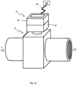
- Fig. 1a shows the basic structure of a field device - designed, for example, as a measuring device for flow measurement.
- the field device can be _as in Fig. 1a indicated - for example to determine a measured variable x of a medium flowing in a pipeline - not shown here - for example a liquid or a flowable dispersion.
- the field device has a measurement sensor S for generating at least one measurement signal that is dependent on the measured variable x to be recorded, which is in Fig. 1a
- the exemplary embodiment shown is formed by means of a measuring tube which can be inserted into the course of the same pipeline and is therefore traversed by the medium carried in the pipeline during operation.
- the field device can therefore also be, for example, a magnetic-inductive flow measuring device (MID) suitable for measuring a volume flow rate.
- MID magnetic-inductive flow measuring device
- the measurement of the volume flow rate is known to take place based on a measuring voltage which is induced by means of a magnetic field perpendicular to the direction of flow passing through the measuring tube, and therefore the medium flowing therein, and which serves as a measuring signal, which is dependent on an instantaneous flow velocity of the medium or that derived therefrom Volume flow rate dependent voltage level and which is picked up by means of two electrodes provided in the sensor.
- the field device comprises a device housed in an electronics housing H.
- the electronics housing H has a housing base body H ⁇ and a housing cover H" closing it.
- the housing base body H ⁇ can, as is quite common with electronics housings for field devices, for example pot-shaped or, as can be seen from a summary of the Fig. 1a , 1b and 6 can be seen, for example also be designed more box-shaped.
- the housing base body H' and/or the housing cover H" can, for example, each be a molded part made of a metal, for example a steel or an aluminum alloy.
- the housing base body H' and/or the housing cover H", for example, can also each consist at least partially or entirely of a plastic.
- the housing base body H' and the housing cover H" can also each be manufactured using an original molding process that is adapted to the material used, for example by casting, die-casting or injection molding.
- the housing base body - for example made from the same material as the housing base body - Housing cover H" can - as in Fig. 1b indicated - be releasably fixed to the housing base body H ⁇ by means of two or more, for example four screw connections.
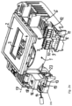
- the device electronics shown here comprises a centrally arranged measurement amplifier 1.
- the measurement amplifier 1 can be formed, for example, by means of an instrument amplifier circuit and can also be set up to transmit the at least one measurement signal, for example the measurement voltage mentioned, largely without any reaction capture and then reinforce.
- a display and operating unit 2 attached, which includes a display element 3 designed, for example, as an LCD display and an operating element 4 formed by means of optical input keys.
- a currently measured measured value for the measured variable here for example the volume flow rate, and/or setting values of various operating parameters of the field device can be displayed.
- the control element 4 an operator can make appropriate entries for controlling and/or programming the device electronics.
- the measured value determined in each case can also be transmitted, for example, via a fieldbus to a central control computer or a programmable logic controller (PLC).
- PLC programmable logic controller
- an IO board 5 namely an input/output circuit built on a printed circuit board, is provided in the device electronics, with which the device electronics, and therefore the field device formed with it, can be connected to a fieldbus.
- the IO board 5 is designed to convert measured values into a data telegram that is suitable for the fieldbus, namely corresponding to a respective fieldbus protocol.
- Different types of IO boards are offered, which support different fieldbus protocols such as HART, Profibus, Modbus, Ethernet IP, etc. The ones in the Fig.
- the second four-pole coupling connection 8 includes a built-in plug 11 mounted on the IO board 5, into which an associated connecting plug 12 can be inserted.
- the two four-pin connecting plugs 10, 11 are each equipped with four spring terminals for connecting individual wires of corresponding connecting cables.
- device electronics also includes a network board 13, namely a circuit of the device electronics or the field device formed with it, which is built on a circuit board and designed as a power supply, which is connected to an external, from Field device remote supply circuit EV, for example a transmitter power supply, a power supply isolator or an AC power supply, is operated.
- the network board 13 - arranged next to the measuring amplifier 1 in the exemplary embodiment shown here - is designed to provide the various operating voltages required by the device electronics or the field device formed with it during operation, for example with a voltage level of less than 20 V (volts).
- the network board 13 or the device electronics formed with it is set up to be operated with mains voltage, for example with 230 V ⁇ 60 Hz (Hertz), as the supply voltage.
- connection line 14 - formed for example by means of a two- or multi-core cable - which is electrically connected to the supply circuit EV and is therefore partially laid external to the electronics housing of the field device, and further via a connection device which is electrically connected to it during operation.
- the connection device comprises a base body 200, in particular at least partially made of an electrically insulating plastic and / or designed as an electronic insert that at least partially encapsulates the device electronics, and a plug connector 15 held thereon.
- the plug connector 15 comprises a first plug connector part 19 which is fixed to the base body 200 and at the same time electrically connected to the network board 13, as well as a second plug connector part 20 which can be connected to the connecting line 14 or is connected during operation and is complementary to the first plug connector part 19.
- the plug connector part 19 has at least one contact pin 19' which is electrically connected to the circuit of the field device, while the plug connector part 20 comprises at least one contact sleeve 20' - here namely with at least one wire of the connecting line 14 or which is connected during operation.
- the connector part 19 and the connector part 20 - as well as from a synopsis of the Fig.
- the plug connector part 19 can - as shown schematically - therefore also be designed, for example, as a built-in plug, while the plug connector part 20 can be, for example, a coupling.
- the connecting line 14 to be connected by means of the connecting device serves to supply the supply voltage, as shown in Fig. 3c indicated, the connector part 19 in addition to the contact pin 19 'at least one further - second - contact pin 19" and the connector part 20 in addition to Contact sleeve 20' has at least one further - second - contact sleeve 20".
- the outer conductor (L) can be connected to the contact sleeve 20' and the neutral conductor (N) can be connected to the additional contact sleeve 20". and thus via the corresponding contact pin 19 'or 19" to the network board 13.
- the possibly provided protective conductor (PE) can also be supplied via the plug connector 15 - namely via a further - third - contact sleeve 20 ". and a corresponding - third - contact pin 19′′′ can be connected to the network board 13.
- the protective conductor (PE) can also be connected, for example, to a grounding plate - not shown here.
- the connecting line 14 to the plug connector part 20, which is designed, for example, as a coupling, this can also have, for example, corresponding - for example two or three - spring clamping elements 21, each of which is electrically connected to one of the contact sleeves 20 ', 20 "or 20". is and in which the individual wires of the connecting line 14 - designed for example as strands or as solid wires - are clamped.
- the plug connector part 20 comprises in the in Fig. 3b In the exemplary embodiment shown, there are therefore exactly three spring clamping elements 21 for clamping the individual wires of the connecting cable 14.
- the connecting cable 14 can, for example, also be designed as just a two-wire connecting cable, of which a first wire for the outer conductor (L) is connected to the first contact sleeve 20 'and a second wire for the neutral conductor (N) is connected to the contact sleeve 20" in such a way that the middle contact sleeve 20", which is also present, remains exposed.
- the connecting cable 14 can also be designed, for example, as a three-wire cable, which additionally In addition to the wires for the external conductor and the neutral conductor, there is a third wire for the protective conductor (PE) connected to the contact sleeve 20′′′.
- a pull-off force of at least 15 N (Newton) must be applied, or that a pull-off force acting on the second connector part 20 with less than 15 N does not cause the same connector part 20 to be removed from the connector part 19, and therefore does not cause the contact sleeve 20 'to be removed from the contact pin 19'.
- Such a requirement is intended to prevent the connector part 20 from being detached too easily, possibly even automatically, from the connector part 19, and therefore the connector 15 being unintentionally disconnected during operation of the field device.
- the connector part 20 must not be able to be accidentally removed, since this can pose an increased safety risk, not least in the immediate vicinity of an electrically conductive liquid.
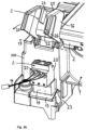
- connection device in order to meet this requirement for device safety or to ensure that a removal force of at least 15 N is required to remove the plug connector part 20, the connection device according to the invention, as also shown in FIG Fig. 2a , 2 B , 3a , 3b , and 3c or their combination can be seen, furthermore a cover flap 16 which is movably mounted on the base body 200 - namely pivotable about an axis 17 - and is, for example, at least partially made of an electrically insulating plastic, for at least partially covering the plug connector 15.
- the cover flap 16 and the bearing provided on the base body 200 for receiving the axis 17 or for pivotably holding the cover flap 16 are shown again enlarged.
- the cover flap 16 can - as already indicated - be designed, for example, as a plastic molding.
- it has a first mounting section 28 with a first axle journal 29 and a second mounting section 30 with a second axle journal 31.
- the holder section 30 is designed to be significantly narrower than the holder section 28 and can therefore be resiliently deformed to a certain extent due to the gap 32. How further from the Fig.
- the bearing shown here for the cover flap 16 includes a recess 33, a first receptacle 34 for the axle journal 29 and a second receptacle 35 for the axle journal 31.
- the holding section 30 can be elastically deformed so that the two axle journals 29, 31 can be fitted into the corresponding receptacles 34, 35 and are then rotatably mounted in the receptacles 34, 35 by releasing the holding section 30 into its initial shape.
- the cover flap 16 is - as can be seen from a synopsis of the Fig. 2a or 2b and 3a or 3b are readily apparent - between a first end position in which the cover flap 16 at least partially covers the plug connector ( Fig. 2a ; Fig. 2b ), and a second end position ( Fig. 3a ; Fig. 3b ) pivotable.
- the cover flap 16 can, for example, move around the axis 17 in the direction of arrow 18 - in Fig. 2a or 2b namely up - or back again - in Fig. 3a or 3b namely downwards - and so out of the in Fig. 2a or 2b shown first end position in an open position - for example in the second end position - are moved.
- the cover flap 16 of the connection device according to the invention is in particular also designed to be able to be pivoted into at least one open position located between the first end position and the second end position and in the same opening position - possibly also coinciding with the second end position - to be able to release the plug connector 15 to the extent that that the at least one contact sleeve 20 'of the second connector part 20 from at least one Contact pin 19' of the first connector part 19 can be removed along a predetermined withdrawal path by the second connector part 20 - as in Fig. 3c indicated, is separated from the first connector part 19 by applying a pull-off force acting in one direction of the pull-off track.
- the cover flap 16 - not least to protect an operator from accidental contact with the supply voltage, which may also be above a permissible contact voltage, even when the electronics housing is open - is also set up to be at least that in the first end position connector part 20 connected to the first connector part 19, thus covering the connector 15 formed in this way to such an extent that touching live parts of the connecting device is prevented even when the electronics housing is open.
- the cover flap 16 - as shown in FIG Fig. 2a or 2b shown constellation can be easily seen - designed so that in the first end position it almost completely covers or almost completely envelops the connector 15.
- the cover flap 16 is in an open position - in Fig. 3b or 3c namely shown in the open position coinciding with the second end position - whereby the Fig. 3a and 3b each show the cover flap 16 in an open position with the plug connector part 20 plugged onto the plug connector part 19.
- the plug connector part 19 of the plug connector 15 is mounted directly on the network board 13 and that the plug connector part 20 can be plugged together with the plug connector part 19 or removed from it again when the cover flap is pivoted into the open position.
- the plug connector 15 is exposed to such an extent that its plug connector part 20 can be easily removed from the plug connector part 19 by an operator, for example to remove the device electronics from the supply circuit or from the network disconnect.
- the operator can also plug the plug connector part 20 back onto the plug connector part 19 with the cover flap pivoted into the same opening position in order to electrically connect the device electronics to the connecting cable or to electrically connect the field device to the supply circuit.
- the cover flap 16 can be closed by pivoting it from the open position into the first end position. This is in Fig. 3b illustrated schematically by arrow 27.
- the housing cover H" can then be screwed back onto the housing base body H ⁇ .
- cover flap 16 of the connection device according to the invention is also intended or set up for this purpose, at least in the first end position with the plug connector part 19 connected connector part 20 to fix; this in particular in such a way that a pull-off force acting on the second connector part 20 with less than 15 N does not cause the at least one contact sleeve of the second connector part 20 to be removed from the at least one contact pin of the first connector part 19, and / or in such a way that to remove the At least one contact sleeve 20 'of the connector part 20 from the at least one contact pin 19' of the connector part 19 requires a removal force of more than 15 N.
- the cover flap has at least one contact area 16+, namely a partial area, on an inside facing the plug connector, which is designed to contact the second plug connector part 20 connected to the first plug connector part 19, and also has the in the Plug connector part 19 inserted plug connector part 20 on an outside facing the cover flap 16 at least one contact area 20+ corresponding to the contact area 16+ of the cover flap 16, namely a partial area which is set up to contact the contact area 16+ of the cover flap 16.
- the portion of the cover flap 16 resting on the outside of the plug connector part 20 can also be shaped or designed in a complementary manner to the same outside in such a way that the same portion of the cover flap 16 rests at least partially flat on the same outside of the plug connector part 20 and at the same time Detaching the connector part 20 from the connector part 19 is formed which prevents a positive connection or a removal of the connector part 20 from the connector part 19.
- the cover flap 16 is therefore further designed to ensure that the second connector part 20 connected to the first connector part 19 forms a positive fit between the cover flap 16 and the connector part 20, in particular counteracting the removal of the connector part 20 from the connector part 19 to contact.
- the cover flap 16 is also set up to contact the - here essentially complementary - contact area 20+ of the plug connector part 20 in the first end position with at least the contact area 16+ or the contact area 16+ assigns one a shape of the contact area 20+ complementary shape.
- the contact area 16+ and the contact area 20+ can, for example, be shaped and designed in such a way that when the cover flap 16 is moved into the first end position, the same contact areas 16+, 20 + a positive fit is formed between the cover flap 16 and the plug connector part 20, which counteracts the removal of the plug connector part 20 from the plug connector part 19.
- the contact area 16+ of the cover flap 16 can also be designed in such a way that it has at least one, for example pin-shaped or web-shaped, shaped element 24, which in the first end position of the cover flap 16 contacts the contact area 20+ of the plug connector part 20 accordingly or that it contacts by means of a such a shaped element 24 is formed.
- a web provided on the inside of the cover flap 16 facing the plug connector 15 serves as a shaped element 24, thus forming the aforementioned contact area 16+.
- the function of the shaped element 24 designed here as a web is again in the Fig. 5a , 5b clarified.
- the cover flap 16, which is also brought into the first end position here, is shown cut open along an imaginary cutting plane, so that the plug connector placed below the cover flap 16 can also be seen.
- the connector part 20 is shown plugged together with the connector part 19 - which is placed here on the network board 13.
- the connector part 20 has three spring clamping elements 21, in which the corresponding wires of the connecting line 14 - each designed, for example, as a solid wire or as strands - are clamped, via which the required supply voltage can in turn be supplied to the field device.
- the cover flap 16 is in the closed position, namely in the first end position, the molded part 24 of the cover flap 16 lies on the second connector part 20, whereby the connector 15 is secured against possible separation.
- Each of the at least two shaped elements 24, 25 - here designed as essentially parallel webs to one another - is also shaped in such a way that their undersides - here namely forming the contact area 16+ - are designed to be complementary to the contact area 20+ of the inserted connector part 20, at least in sections; This in particular also in such a way that in the first end position of the cover flap 16, each of the two - here each web-shaped - shaped elements 24, 25 contacts the second connector part 20 flatly.
- each of the two shaped elements 24, 25 is dimensioned such that the respective lower end of each of the two webs 24, 25 contacts the contact area 20+ of the plug connector part 20 underneath, which results in the plug connector part 20 being pulled off automatically or unintentionally , not least in the event of vibrations of the electronics housing or the base body 200, is prevented.
- a distance between a respective end facing the axis 17 of each of the shaped elements 24, 25 of the same axis 17 can also be dimensioned such that at least one of these With the cover flap 16 in the first end position, the ends contact a further corresponding contact area of the connector part 20 in order to further improve the holding effect of the positive connection between the cover flap 16 and the connector part 20.
- the fixation of the plug connector part 20 connected to the plug connector part 19 can also be supported by further measures, for example measures that prevent spontaneous opening of the cover flap 16 during operation of the field device, such as corresponding latching elements of the connection device and/or further shaped elements provided on the housing cover .
- the cover flap 19 and the base body 200 are therefore further designed to form a snap connection in the first end position of the cover flap 16, namely a connection in which the inherent elasticity of the cover flap 19 and the base body 200 is used a releasable positive connection between the cover flap 19 and the base body 200 is produced by pressing.
- the cover flap in this embodiment of the invention is in particular also designed to snap into a corresponding locking element 23 of the base body 200 in the first end position by means of at least one locking element 22, forming a - here self-retaining, but nevertheless releasable - form fit.
- the locking element 22 of the cover flap 16 in the exemplary embodiment shown here is essentially hook-shaped, while the locking element 23 of the base body 200, which corresponds to at least one hook-shaped locking element 22 of the cover flap, is only provided by a web or web provided on the base body 200. a rib provided on the base body is formed.
- the locking element 23 of the base body 200 can, for example, also be essentially hook-shaped or essentially eye-shaped.
- Fig. 2a or 2b it can be seen that when the cover flap 16 is in the first end position, the locking element 22 is locked into the locking element 23 by placing a hook-shaped end region of the locking element 22 behind the locking element 23, viewed in the closing direction.
- the locking element 22 moves inwards towards the plug connector 19 or away from the locking element 23 of the base body 200.
- the deformation force must be so great that the locking element 22 is completely released from the locking element again and the locking between the two locking elements 22, 23 is completely released again.
- the restoring forces applied by the cover flap 16, namely counteracting a deformation that allows the cover flap to be opened must be sufficiently high that the snap lock can be released spontaneously or the cover flap 16 can be opened spontaneously during operation of the field device, not least in the event of vibrations in the electronics device. Housing or the device electronics housed therein is safely avoided.
- FIG. 6 a further variant of the invention is shown, in which the housing cover H" and the cover flap 16 are set up for fixing the cover flap 16 brought into the first end position, and therefore for securing the connector produced by connecting the plug connector part 20 to the plug connector part 19 , to contact each other in the installed position, namely with the cover flap 16 in the first end position and the housing cover H "connected to the housing base body H ', in particular in such a way that a force and force counteracting a pivoting of the cover flap from the first end position / or positive connection is formed between the cover flap and the housing cover.
- the housing cover H" has at least one contact area H#, namely a partial area, on an inside facing the connection device or the device electronics, which is designed to contact the cover flap 16 located in the first end position, and has the cover flap 16 on an outside facing the housing cover at least one contact area 16# corresponding to the same contact area H# of the housing cover H ⁇ , namely a partial area which is set up to contact the contact area H# of the housing cover in the installed position.
- the contact area H# of the housing cover can be formed in that the housing cover has at least one - for example pin-shaped or web-shaped - shaped element 30 on the inside facing the connection device or the device electronics, which is designed for this purpose , in the installed position, forming the contact area H#, to contact the corresponding contact area 16# of the cover flap 16 located in the first end position, for example by forming a positive connection between the housing cover and the cover flap.
- a form fit formed in this way can also be designed in such a way that, in the installed position, the same form element 30 fixes the cover flap 16 in the first end position without play, for example by the form element 30 is dimensioned so that in the installed position it additionally experiences a deformation force, which causes a slight elastic deformation of the shaped element 30, which is nevertheless sufficient for fixing the cover flap 16 in the first end position.
- the cover flap 16 and the plug connector 15 can also be dimensioned in such a way that they are coordinated with one another so that When the cover flap 16 is in the end position, it and/or the plug connector 15 are elastically deformed in such a way that, as a result, additional holding forces are generated in the connecting device which keep the plug connector part 20 pressed against the plug connector part 19, whereby the plug connector part 20 connected to the plug connector part 19 is even better against any loosening of the connector part 19 can be secured.
- This can be achieved very easily, for example, by a height that is suitable for the shaped elements 24, 25.
Landscapes
- Physics & Mathematics (AREA)
- General Physics & Mathematics (AREA)
- Fluid Mechanics (AREA)
- Engineering & Computer Science (AREA)
- Manufacturing & Machinery (AREA)
- Details Of Connecting Devices For Male And Female Coupling (AREA)
- Connector Housings Or Holding Contact Members (AREA)
Applications Claiming Priority (3)
| Application Number | Priority Date | Filing Date | Title |
|---|---|---|---|
| DE201310111696 DE102013111696A1 (de) | 2013-10-23 | 2013-10-23 | Anschlussvorrichtung für ein Feldgerät sowie Feldgerät mit einer solchen Anschlussvorrichtung |
| EP14761865.6A EP3061156B1 (fr) | 2013-10-23 | 2014-09-10 | Appareil de terrain et procédure de raccordement d'une connexion électrique à cet appareil de terrain |
| PCT/EP2014/069276 WO2015058897A1 (fr) | 2013-10-23 | 2014-09-10 | Dispositif de raccordement pour appareil de terrain et appareil de terrain équipé d'un tel dispositif de raccordement |
Related Parent Applications (2)
| Application Number | Title | Priority Date | Filing Date |
|---|---|---|---|
| EP14761865.6A Division EP3061156B1 (fr) | 2013-10-23 | 2014-09-10 | Appareil de terrain et procédure de raccordement d'une connexion électrique à cet appareil de terrain |
| EP14761865.6A Division-Into EP3061156B1 (fr) | 2013-10-23 | 2014-09-10 | Appareil de terrain et procédure de raccordement d'une connexion électrique à cet appareil de terrain |
Publications (2)
| Publication Number | Publication Date |
|---|---|
| EP4336669A2 true EP4336669A2 (fr) | 2024-03-13 |
| EP4336669A3 EP4336669A3 (fr) | 2024-06-05 |
Family
ID=51518777
Family Applications (2)
| Application Number | Title | Priority Date | Filing Date |
|---|---|---|---|
| EP24153687.9A Pending EP4336669A3 (fr) | 2013-10-23 | 2014-09-10 | Dispositif de raccordement pour un appareil de terrain ainsi qu'appareil de terrain doté d'un tel dispositif de raccordement |
| EP14761865.6A Active EP3061156B1 (fr) | 2013-10-23 | 2014-09-10 | Appareil de terrain et procédure de raccordement d'une connexion électrique à cet appareil de terrain |
Family Applications After (1)
| Application Number | Title | Priority Date | Filing Date |
|---|---|---|---|
| EP14761865.6A Active EP3061156B1 (fr) | 2013-10-23 | 2014-09-10 | Appareil de terrain et procédure de raccordement d'une connexion électrique à cet appareil de terrain |
Country Status (5)
| Country | Link |
|---|---|
| US (3) | USRE49785E1 (fr) |
| EP (2) | EP4336669A3 (fr) |
| CN (2) | CN114094391B (fr) |
| DE (1) | DE102013111696A1 (fr) |
| WO (1) | WO2015058897A1 (fr) |
Families Citing this family (18)
| Publication number | Priority date | Publication date | Assignee | Title |
|---|---|---|---|---|
| DE102013111696A1 (de) * | 2013-10-23 | 2015-04-23 | Endress + Hauser Flowtec Ag | Anschlussvorrichtung für ein Feldgerät sowie Feldgerät mit einer solchen Anschlussvorrichtung |
| AT517608B1 (de) * | 2016-01-21 | 2017-03-15 | Avl List Gmbh | Elektronikeinheit für ein Durchflussmessgerät |
| DE102016110050B4 (de) | 2016-05-31 | 2020-01-23 | Endress+Hauser SE+Co. KG | Steck-Verbindung zur elektrischen Kontaktierung einer Leiterplatte |
| DE102016116091A1 (de) | 2016-08-30 | 2018-03-01 | DEHN + SÖHNE GmbH + Co. KG. | Elektrischer Anschlussverbinder mit Berührungsschutz |
| DE102016120329A1 (de) * | 2016-10-25 | 2018-04-26 | Festool Gmbh | Anschlussvorrichtung eines Elektrogeräts oder eines Energiespeichers |
| DE102017114555A1 (de) | 2017-06-29 | 2019-01-03 | Endress+Hauser SE+Co. KG | Messsystem |
| CN108199165A (zh) * | 2018-02-28 | 2018-06-22 | 成都瑞联电气股份有限公司 | 一种多功能安装屏回路切换装置 |
| DE102019114523A1 (de) * | 2019-05-29 | 2020-12-03 | Valeo Siemens Eautomotive Germany Gmbh | Antriebseinrichtung für ein elektrisch antreibbares Fahrzeug und Fahrzeug |
| DE102019128623A1 (de) * | 2019-10-23 | 2021-04-29 | Endress+Hauser Conducta Gmbh+Co. Kg | Feldgerät mit Elektronikmodul samt Abdeckhaube |
| DE102019134790A1 (de) * | 2019-12-17 | 2021-06-17 | Valeo Siemens Eautomotive Germany Gmbh | Stromrichtereinrichtung und Antriebseinrichtung für ein elektrisch antreibbares Fahrzeug |
| US11824934B2 (en) | 2020-09-10 | 2023-11-21 | Fisher-Rosemount Systems, Inc. | Security systems for use in implementing highly-versatile field devices and communication networks in control and automation systems |
| US12255973B2 (en) | 2020-09-10 | 2025-03-18 | Fisher-Rosemount Systems, Inc. | Highly-versatile field devices and communication networks for use in control and automation systems |
| US11256238B1 (en) * | 2020-09-10 | 2022-02-22 | Fisher-Rosemount Systems, Inc. | Network resource management in a communication network for control and automation systems |
| US11531325B2 (en) | 2020-09-10 | 2022-12-20 | Fisher-Rosemount Systems, Inc. | Node management of nodal communication networks for highly versatile field devices in control and automation systems |
| US11824650B2 (en) | 2020-09-10 | 2023-11-21 | Fisher-Rosemount Systems, Inc. | Publish-subscribe communication architecture for highly-versatile field devices in control and automation systems |
| EP4114156B1 (fr) * | 2021-06-29 | 2025-08-06 | Abb Schweiz Ag | Unité de bloc terminal pour un dispositif d'entrée/sortie d'un système de commande de processus modulaire |
| EP4621385A1 (fr) | 2024-03-19 | 2025-09-24 | optek-Danulat GmbH | Dispositif de détermination optique d'une concentration de substance d'un fluide |
| CN118330302B (zh) * | 2024-06-13 | 2024-09-27 | 长春浩泰科技有限公司 | 一种电力系统电压在线监测装置 |
Citations (7)
| Publication number | Priority date | Publication date | Assignee | Title |
|---|---|---|---|---|
| WO1988002476A1 (fr) | 1986-10-03 | 1988-04-07 | Micro Motion, Inc. | Dispositif de mesure de transfert a des fins de controle |
| WO1988002853A1 (fr) | 1986-10-09 | 1988-04-21 | Micro Motion, Inc. | Appareil et procedes de mesure de la densite d'un fluide inconnu en utilisant un debitmetre de coriolis |
| EP0816807A2 (fr) | 1996-03-11 | 1998-01-07 | The Foxboro Company | Méthode et dispositif pour la correction des facteurs de dégradation de la performance d'un débitmètre massique de Coriolis |
| US6452493B1 (en) | 2000-01-19 | 2002-09-17 | Sor, Inc. | Process control instrument with multiple functions |
| EP1591977A1 (fr) | 2004-04-30 | 2005-11-02 | Endress + Hauser Conducta Gesellschaft für Mess- und Regeltechnik mbH + Co.KG. | Procédé de signalisation la condition d'alarme d'un appareil de champ de la technologie d'automatisation |
| US20100101817A1 (en) | 2008-10-23 | 2010-04-29 | Abb Technology Ag | Connecting box for field device |
| US20110317390A1 (en) | 2010-06-21 | 2011-12-29 | Endress + Hauser Flowtec Ag | Electronics housing for an electronic device, and a device formed therewith |
Family Cites Families (42)
| Publication number | Priority date | Publication date | Assignee | Title |
|---|---|---|---|---|
| US3659248A (en) | 1970-05-04 | 1972-04-25 | Gen Electric | Combined socket cover and plug retainer |
| IT1056449B (it) * | 1976-02-06 | 1982-01-30 | Bassani Spa | Struttura di contattore elettrico ad elementi componibili |
| GB1580037A (en) | 1977-05-18 | 1980-11-26 | Latham M J | Guard intended to be mounted around and to protect an electrical wall fitting |
| US4899048A (en) * | 1987-04-27 | 1990-02-06 | Printware, Inc. | Focused optical beam encoder of position |
| US4915638A (en) * | 1988-04-29 | 1990-04-10 | Anthony Domian | Protective enclosure for electrical outlets |
| JPH0714575U (ja) | 1991-12-27 | 1995-03-10 | センチュリーメディカル株式会社 | コネクターのロック機構 |
| JP2596866Y2 (ja) * | 1993-09-11 | 1999-06-21 | 古河電気工業株式会社 | 嵌合確認機構付コネクタ |
| US5606299A (en) * | 1995-11-14 | 1997-02-25 | Eaton Corporation | Modular surge suppressor |
| DE29603161U1 (de) * | 1996-02-22 | 1996-05-15 | Gebr. Merten Gmbh & Co Kg, 51643 Gummersbach | Abdeckung für ein elektrisches Gehäuse |
| US5906497A (en) * | 1997-12-12 | 1999-05-25 | Hewlett Packard Company | Processor retention frame and extraction device |
| US5942737A (en) * | 1998-10-15 | 1999-08-24 | General Motors Corporation | High voltage guard with interlock |
| DE19913262A1 (de) * | 1999-03-24 | 2000-09-28 | Heidenhain Gmbh Dr Johannes | Winkelmeßeinrichtung |
| JP4034125B2 (ja) * | 2002-06-06 | 2008-01-16 | 日本圧着端子製造株式会社 | 電気的接続装置 |
| AUPS315002A0 (en) * | 2002-06-25 | 2002-07-18 | Resmed Limited | Method & apparatus for control of appliance coupler retention and withdrawal forces |
| US7307823B2 (en) * | 2003-05-22 | 2007-12-11 | Eaton Corporation | Modular surge suppressor system and surge suppressor module |
| US6811425B1 (en) * | 2003-09-25 | 2004-11-02 | Excel Cell Electronic Co., Ltd. | Controller module responsive to input signals for controlling an electrical appliance |
| US7009126B2 (en) * | 2003-11-24 | 2006-03-07 | Square D Company | Load terminal cover |
| US20050202706A1 (en) * | 2004-03-09 | 2005-09-15 | Neal Bonavia | Snap ring connector system |
| JP3969400B2 (ja) * | 2004-04-09 | 2007-09-05 | 松下電工株式会社 | コネクタ |
| JP4432854B2 (ja) * | 2005-07-22 | 2010-03-17 | パナソニック電工株式会社 | 配線器具の防雨構造 |
| DE102006016882B4 (de) * | 2006-04-04 | 2008-01-31 | ITT Manufacturing Enterprises, Inc., Wilmington | Steckverbinder |
| US20090325423A1 (en) * | 2006-09-21 | 2009-12-31 | Georg Bollinger | Adapter for a main current path tap of a switching device |
| US8288651B2 (en) * | 2007-09-28 | 2012-10-16 | Kenneth Smith | Weatherproof connector |
| FR2922052B1 (fr) * | 2007-10-05 | 2009-11-20 | Midi Moulages Plast | Prise de courant enfichable comportant un corps de prise ouvrable et un bloc de connexion mobile a pivotement |
| US8013245B2 (en) * | 2008-10-31 | 2011-09-06 | Hubbell Incorporated | Weatherproof cover assembly for an electrical box having a water intrusion barrier |
| DE102009021594B4 (de) * | 2009-04-09 | 2018-04-12 | Phoenix Contact Gmbh & Co. Kg | Elektrischer Steckverbinder und elektrische Steckverbindung sowie Verfahren zum Anschließen der Andern eines mehradrigen Kabels an einen elektrischen Steckverbinder |
| TWI369040B (en) * | 2009-12-04 | 2012-07-21 | Emcom Technology Inc | Engaging connector and operating method thereof |
| WO2011073758A1 (fr) * | 2009-12-14 | 2011-06-23 | Panasonic Electric Works Co., Ltd. | Ensemble de fiche et de prise |
| FR2971372B1 (fr) * | 2011-02-03 | 2013-11-29 | Tyco Electronics France Sas | Connecteur enfichable avec mecanisme de support de bonnette de protection arriere |
| US8496488B2 (en) * | 2011-03-24 | 2013-07-30 | Cisco Technology, Inc. | Power input terminal block housing and cover |
| DE102011016481B4 (de) * | 2011-04-08 | 2015-05-13 | Temtec Fahrzeugtechnik Entwicklungsgesellschaft Mbh | Verriegelungssystem für eine an einem Kraftfahrzeug, einer Ladestation oder einer Wand angeordnete Steckkuppeleinrichtung und Steckkuppeleinrichtung |
| EP2515380B1 (fr) | 2011-04-19 | 2016-05-25 | Pepperl + Fuchs GmbH | Appareils de terrain pour une meilleure sécurité |
| EP2549515A1 (fr) * | 2011-07-21 | 2013-01-23 | Eaton Industries GmbH | Agencement de commutation pour création et/ou séparation d'une connexion d'une fiche avec une contre-fiche |
| DE102012022750A1 (de) | 2011-11-22 | 2013-05-23 | Ifm Electronic Gmbh | Vertikaler Potenzialausgleichsleiter in einem elektronischen Gerät |
| US9437959B2 (en) * | 2012-03-08 | 2016-09-06 | Sigma Electric Manufacturing Corporation | Slim line while in use cover and methods for making and using the same |
| DE102012105509B4 (de) * | 2012-06-25 | 2018-04-05 | Wago Verwaltungsgesellschaft Mbh | Elektronikgerätegehäuse |
| US8876539B2 (en) * | 2013-03-27 | 2014-11-04 | Erich Jaeger Gmbh & Co. Kg | Plug for an electrical plug-and-socket connection |
| US9093230B2 (en) * | 2013-08-09 | 2015-07-28 | Eaton Corporation | Hidden/sliding door system for field-installed accessory access |
| US9065203B2 (en) * | 2013-08-12 | 2015-06-23 | Craig Davies | Apparatuses and methods for securing a connection of an electrical connection assembly |
| EP2851656B1 (fr) * | 2013-09-23 | 2015-04-29 | SICK STEGMANN GmbH | Boîtier pour un capteur |
| DE102013111696A1 (de) | 2013-10-23 | 2015-04-23 | Endress + Hauser Flowtec Ag | Anschlussvorrichtung für ein Feldgerät sowie Feldgerät mit einer solchen Anschlussvorrichtung |
| US9520692B2 (en) * | 2014-01-31 | 2016-12-13 | Panduit Corp. | Audio visual faceplate with integrated hinged termination method for circular connector |
-
2013
- 2013-10-23 DE DE201310111696 patent/DE102013111696A1/de active Pending
-
2014
- 2014-09-10 EP EP24153687.9A patent/EP4336669A3/fr active Pending
- 2014-09-10 CN CN202111085445.0A patent/CN114094391B/zh active Active
- 2014-09-10 US US17/330,924 patent/USRE49785E1/en active Active
- 2014-09-10 WO PCT/EP2014/069276 patent/WO2015058897A1/fr not_active Ceased
- 2014-09-10 CN CN201480058322.XA patent/CN105659443B/zh active Active
- 2014-09-10 EP EP14761865.6A patent/EP3061156B1/fr active Active
- 2014-09-10 US US15/031,001 patent/US10305212B2/en not_active Ceased
-
2019
- 2019-04-09 US US16/378,776 patent/US10615529B2/en active Active
Patent Citations (7)
| Publication number | Priority date | Publication date | Assignee | Title |
|---|---|---|---|---|
| WO1988002476A1 (fr) | 1986-10-03 | 1988-04-07 | Micro Motion, Inc. | Dispositif de mesure de transfert a des fins de controle |
| WO1988002853A1 (fr) | 1986-10-09 | 1988-04-21 | Micro Motion, Inc. | Appareil et procedes de mesure de la densite d'un fluide inconnu en utilisant un debitmetre de coriolis |
| EP0816807A2 (fr) | 1996-03-11 | 1998-01-07 | The Foxboro Company | Méthode et dispositif pour la correction des facteurs de dégradation de la performance d'un débitmètre massique de Coriolis |
| US6452493B1 (en) | 2000-01-19 | 2002-09-17 | Sor, Inc. | Process control instrument with multiple functions |
| EP1591977A1 (fr) | 2004-04-30 | 2005-11-02 | Endress + Hauser Conducta Gesellschaft für Mess- und Regeltechnik mbH + Co.KG. | Procédé de signalisation la condition d'alarme d'un appareil de champ de la technologie d'automatisation |
| US20100101817A1 (en) | 2008-10-23 | 2010-04-29 | Abb Technology Ag | Connecting box for field device |
| US20110317390A1 (en) | 2010-06-21 | 2011-12-29 | Endress + Hauser Flowtec Ag | Electronics housing for an electronic device, and a device formed therewith |
Also Published As
| Publication number | Publication date |
|---|---|
| CN105659443A (zh) | 2016-06-08 |
| CN114094391A (zh) | 2022-02-25 |
| WO2015058897A1 (fr) | 2015-04-30 |
| CN105659443B (zh) | 2021-10-01 |
| CN114094391B (zh) | 2024-06-21 |
| USRE49785E1 (en) | 2024-01-02 |
| US10615529B2 (en) | 2020-04-07 |
| US20160254609A1 (en) | 2016-09-01 |
| EP4336669A3 (fr) | 2024-06-05 |
| US10305212B2 (en) | 2019-05-28 |
| DE102013111696A1 (de) | 2015-04-23 |
| EP3061156B1 (fr) | 2024-03-20 |
| EP3061156A1 (fr) | 2016-08-31 |
| US20190237890A1 (en) | 2019-08-01 |
Similar Documents
| Publication | Publication Date | Title |
|---|---|---|
| EP3061156B1 (fr) | Appareil de terrain et procédure de raccordement d'une connexion électrique à cet appareil de terrain | |
| EP1130368B1 (fr) | Dispositif de mesure à détecteur suspendu à une ligne et procédé pour raccourcir la ligne | |
| WO2011160949A1 (fr) | Boîtier électronique pour appareil électronique et appareil comprenant ce boîtier | |
| EP0945714A1 (fr) | Dispositif électronique utilisé dans un environnement susceptible d'explosion | |
| WO2013087390A1 (fr) | Couvercle de boîtier pour un boîtier électronique et boîtier électronique ainsi constitué | |
| EP2683227A1 (fr) | Module électronique destiné à être inséré dans une unité de support | |
| EP1008836B1 (fr) | Boítier pour un transmetteur | |
| EP3948166B1 (fr) | Module supplémentaire pour un dispositif de terrain | |
| WO2023030771A1 (fr) | Dispositif de réception d'un affichage pour un appareil de terrain d'automatisation | |
| DE202016105839U1 (de) | Anzeige- und/oder Bedienmodul | |
| WO2021121743A1 (fr) | Dispositif de transmission sans fil d'un signal | |
| EP3552462A1 (fr) | Module électronique | |
| WO2023030770A1 (fr) | Dispositif d'automatisation de terrain | |
| WO2014154471A1 (fr) | Appareil de mesure équipé d'une interface | |
| EP3645979B1 (fr) | Système de mesure | |
| EP3178301A1 (fr) | Appareil de terrain de la technique d'automatisation | |
| EP1966567B1 (fr) | Systeme a element electronique rapporte pour boitier d'appareil de mesure | |
| DE102015105407A1 (de) | Verfahren, Netzwerk und Vorrichtung zur Steuerung und/oder Versorgung zumindest einer Maschine | |
| EP4487661B1 (fr) | Dispositif de terrain modulaire | |
| DE202016106172U1 (de) | Feldgerät | |
| EP2656415B1 (fr) | Sécurité de transport pour une unité de batterie | |
| EP4380328A1 (fr) | Appareil de terrain de la technique d'automatisation | |
| DE10236226A1 (de) | Vorrichtung zur Bestimmung und/oder Überwachung einer physikalischen oder chemischen Größe | |
| DE3010739A1 (de) | Fluessigkeitsfuehler mit oder ohne eingebauter elektronik, in besonders universeller, kleiner, flacher und damit material- und platzsparender bauweise mit auomatischer einnahme einer richtigen gebrauchslage bei loser aufstellung, zur weiteren verwendung als fest montierbarer niveaufuehler an behaelterwaenden etc., erweiterungsmoeglichkeit zu einem schwimmerschalter sowie anschluss- bzw. ansteckmoeglichkeit weiterer fluessigkeitsfuehler | |
| DE202013105768U1 (de) | Anschlusssystem für eine Sekundärleitung an ein Netzteil |
Legal Events
| Date | Code | Title | Description |
|---|---|---|---|
| PUAI | Public reference made under article 153(3) epc to a published international application that has entered the european phase |
Free format text: ORIGINAL CODE: 0009012 |
|
| STAA | Information on the status of an ep patent application or granted ep patent |
Free format text: STATUS: THE APPLICATION HAS BEEN PUBLISHED |
|
| AC | Divisional application: reference to earlier application |
Ref document number: 3061156 Country of ref document: EP Kind code of ref document: P |
|
| AK | Designated contracting states |
Kind code of ref document: A2 Designated state(s): AL AT BE BG CH CY CZ DE DK EE ES FI FR GB GR HR HU IE IS IT LI LT LU LV MC MK MT NL NO PL PT RO RS SE SI SK SM TR |
|
| REG | Reference to a national code |
Ref country code: DE Ref legal event code: R079 Free format text: PREVIOUS MAIN CLASS: H01R0013533000 Ipc: G01F0015063000 |
|
| PUAL | Search report despatched |
Free format text: ORIGINAL CODE: 0009013 |
|
| AK | Designated contracting states |
Kind code of ref document: A3 Designated state(s): AL AT BE BG CH CY CZ DE DK EE ES FI FR GB GR HR HU IE IS IT LI LT LU LV MC MK MT NL NO PL PT RO RS SE SI SK SM TR |
|
| RIC1 | Information provided on ipc code assigned before grant |
Ipc: H01R 13/533 20060101ALN20240502BHEP Ipc: H01R 105/00 20060101ALN20240502BHEP Ipc: H01R 24/30 20110101ALN20240502BHEP Ipc: G08C 19/00 20060101ALN20240502BHEP Ipc: G01R 1/04 20060101ALN20240502BHEP Ipc: H01R 13/639 20060101ALI20240502BHEP Ipc: H01R 13/447 20060101ALI20240502BHEP Ipc: G01F 15/063 20220101AFI20240502BHEP |
|
| STAA | Information on the status of an ep patent application or granted ep patent |
Free format text: STATUS: REQUEST FOR EXAMINATION WAS MADE |
|
| 17P | Request for examination filed |
Effective date: 20241105 |
|
| RBV | Designated contracting states (corrected) |
Designated state(s): AL AT BE BG CH CY CZ DE DK EE ES FI FR GB GR HR HU IE IS IT LI LT LU LV MC MK MT NL NO PL PT RO RS SE SI SK SM TR |
|
| STAA | Information on the status of an ep patent application or granted ep patent |
Free format text: STATUS: EXAMINATION IS IN PROGRESS |
|
| 17Q | First examination report despatched |
Effective date: 20260313 |