EP4336860B1 - Wärmesenke-entlüftung - Google Patents
Wärmesenke-entlüftung Download PDFInfo
- Publication number
- EP4336860B1 EP4336860B1 EP23194096.6A EP23194096A EP4336860B1 EP 4336860 B1 EP4336860 B1 EP 4336860B1 EP 23194096 A EP23194096 A EP 23194096A EP 4336860 B1 EP4336860 B1 EP 4336860B1
- Authority
- EP
- European Patent Office
- Prior art keywords
- vent
- equipment according
- fin
- electronic component
- plate
- Prior art date
- Legal status (The legal status is an assumption and is not a legal conclusion. Google has not performed a legal analysis and makes no representation as to the accuracy of the status listed.)
- Active
Links
Images

Classifications
-
- H—ELECTRICITY
- H04—ELECTRIC COMMUNICATION TECHNIQUE
- H04R—LOUDSPEAKERS, MICROPHONES, GRAMOPHONE PICK-UPS OR LIKE ACOUSTIC ELECTROMECHANICAL TRANSDUCERS; ELECTRIC HEARING AIDS; PUBLIC ADDRESS SYSTEMS
- H04R1/00—Details of transducers, loudspeakers or microphones
- H04R1/02—Casings; Cabinets ; Supports therefor; Mountings therein
-
- H—ELECTRICITY
- H04—ELECTRIC COMMUNICATION TECHNIQUE
- H04N—PICTORIAL COMMUNICATION, e.g. TELEVISION
- H04N21/00—Selective content distribution, e.g. interactive television or video on demand [VOD]
- H04N21/40—Client devices specifically adapted for the reception of or interaction with content, e.g. set-top-box [STB]; Operations thereof
- H04N21/41—Structure of client; Structure of client peripherals
- H04N21/426—Internal components of the client ; Characteristics thereof
-
- H—ELECTRICITY
- H04—ELECTRIC COMMUNICATION TECHNIQUE
- H04R—LOUDSPEAKERS, MICROPHONES, GRAMOPHONE PICK-UPS OR LIKE ACOUSTIC ELECTROMECHANICAL TRANSDUCERS; ELECTRIC HEARING AIDS; PUBLIC ADDRESS SYSTEMS
- H04R1/00—Details of transducers, loudspeakers or microphones
- H04R1/02—Casings; Cabinets ; Supports therefor; Mountings therein
- H04R1/025—Arrangements for fixing loudspeaker transducers, e.g. in a box, furniture
-
- H—ELECTRICITY
- H04—ELECTRIC COMMUNICATION TECHNIQUE
- H04R—LOUDSPEAKERS, MICROPHONES, GRAMOPHONE PICK-UPS OR LIKE ACOUSTIC ELECTROMECHANICAL TRANSDUCERS; ELECTRIC HEARING AIDS; PUBLIC ADDRESS SYSTEMS
- H04R1/00—Details of transducers, loudspeakers or microphones
- H04R1/02—Casings; Cabinets ; Supports therefor; Mountings therein
- H04R1/028—Casings; Cabinets ; Supports therefor; Mountings therein associated with devices performing functions other than acoustics, e.g. electric candles
-
- H—ELECTRICITY
- H04—ELECTRIC COMMUNICATION TECHNIQUE
- H04R—LOUDSPEAKERS, MICROPHONES, GRAMOPHONE PICK-UPS OR LIKE ACOUSTIC ELECTROMECHANICAL TRANSDUCERS; ELECTRIC HEARING AIDS; PUBLIC ADDRESS SYSTEMS
- H04R1/00—Details of transducers, loudspeakers or microphones
- H04R1/20—Arrangements for obtaining desired frequency or directional characteristics
- H04R1/22—Arrangements for obtaining desired frequency or directional characteristics for obtaining desired frequency characteristic only
- H04R1/28—Transducer mountings or enclosures modified by provision of mechanical or acoustic impedances, e.g. resonator, damping means
- H04R1/2807—Enclosures comprising vibrating or resonating arrangements
- H04R1/2815—Enclosures comprising vibrating or resonating arrangements of the bass reflex type
- H04R1/2823—Vents, i.e. ports, e.g. shape thereof or tuning thereof with damping material
- H04R1/2826—Vents, i.e. ports, e.g. shape thereof or tuning thereof with damping material for loudspeaker transducers
-
- H—ELECTRICITY
- H05—ELECTRIC TECHNIQUES NOT OTHERWISE PROVIDED FOR
- H05K—PRINTED CIRCUITS; CASINGS OR CONSTRUCTIONAL DETAILS OF ELECTRIC APPARATUS; MANUFACTURE OF ASSEMBLAGES OF ELECTRICAL COMPONENTS
- H05K7/00—Constructional details common to different types of electric apparatus
- H05K7/20—Modifications to facilitate cooling, ventilating, or heating
- H05K7/20009—Modifications to facilitate cooling, ventilating, or heating using a gaseous coolant in electronic enclosures
- H05K7/20127—Natural convection
-
- H—ELECTRICITY
- H05—ELECTRIC TECHNIQUES NOT OTHERWISE PROVIDED FOR
- H05K—PRINTED CIRCUITS; CASINGS OR CONSTRUCTIONAL DETAILS OF ELECTRIC APPARATUS; MANUFACTURE OF ASSEMBLAGES OF ELECTRICAL COMPONENTS
- H05K7/00—Constructional details common to different types of electric apparatus
- H05K7/20—Modifications to facilitate cooling, ventilating, or heating
- H05K7/2039—Modifications to facilitate cooling, ventilating, or heating characterised by the heat transfer by conduction from the heat generating element to a dissipating body
-
- H—ELECTRICITY
- H04—ELECTRIC COMMUNICATION TECHNIQUE
- H04R—LOUDSPEAKERS, MICROPHONES, GRAMOPHONE PICK-UPS OR LIKE ACOUSTIC ELECTROMECHANICAL TRANSDUCERS; ELECTRIC HEARING AIDS; PUBLIC ADDRESS SYSTEMS
- H04R1/00—Details of transducers, loudspeakers or microphones
- H04R1/06—Arranging circuit leads; Relieving strain on circuit leads
-
- H—ELECTRICITY
- H04—ELECTRIC COMMUNICATION TECHNIQUE
- H04R—LOUDSPEAKERS, MICROPHONES, GRAMOPHONE PICK-UPS OR LIKE ACOUSTIC ELECTROMECHANICAL TRANSDUCERS; ELECTRIC HEARING AIDS; PUBLIC ADDRESS SYSTEMS
- H04R2201/00—Details of transducers, loudspeakers or microphones covered by H04R1/00 but not provided for in any of its subgroups
- H04R2201/02—Details casings, cabinets or mounting therein for transducers covered by H04R1/02 but not provided for in any of its subgroups
- H04R2201/028—Structural combinations of loudspeakers with built-in power amplifiers, e.g. in the same acoustic enclosure
-
- H—ELECTRICITY
- H04—ELECTRIC COMMUNICATION TECHNIQUE
- H04R—LOUDSPEAKERS, MICROPHONES, GRAMOPHONE PICK-UPS OR LIKE ACOUSTIC ELECTROMECHANICAL TRANSDUCERS; ELECTRIC HEARING AIDS; PUBLIC ADDRESS SYSTEMS
- H04R9/00—Transducers of moving-coil, moving-strip, or moving-wire type
- H04R9/02—Details
- H04R9/022—Cooling arrangements
Definitions
- the invention relates to the field of electrical equipment integrating an acoustic enclosure.
- acoustic enclosure comprising a subwoofer and a loudspeaker, as well as various electronic components.
- These electrical devices include “enhanced” set-top boxes, smart speakers, voice assistants, etc.
- the generally very compact design of these devices requires integrating all their functionalities into a reduced volume.
- the presence of the acoustic enclosure reduces the volume available to integrate the electronic components of the various functions (acoustic and others).
- the volume of air around the electronic components is therefore reduced, which is detrimental to the cooling of said electronic components and causes significant problems of thermal diffusion.
- the invention aims to improve heat dissipation in electrical equipment incorporating an acoustic enclosure.
- the tubular part of the vent forms an additional dissipation surface that is added to that of the thermal conductive element.
- the surface of the vent is in contact with a significant air flow, which further improves the dissipation of the heat produced by the electronic component.
- the thermal conductive element comprises a plate which extends in a plane perpendicular to a longitudinal axis of the vent, and in which the vent widens at said end to open onto said conductive plate.
- vent when viewed in section according to a plane perpendicular to a longitudinal axis of the vent, has an oblong shape.
- vent includes fins extending from an inner surface of the vent and parallel to a longitudinal axis of the vent.
- the equipment according to the invention comprises a cable passage formed on or in a fin, or between two adjacent fins, the cable passage extending along a length of said fin(s).
- the cable passage comprises a groove formed at a surface of a fin, said surface being opposite the internal surface of the vent from which said fin extends.
- equipment as previously described, comprising a plurality of vents having parallel longitudinal axes.
- the plurality of vents comprises at least two vents each comprising a wall in contact with or merged with a wall of the other vent.
- thermally conductive element comprises a plate forming a portion or all of a face of the box.
- thermal coupling between the thermally conductive element and the electronic component is achieved by a thermal connection means positioned between the thermally conductive element and the electronic component.
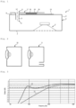
- the invention is here implemented in a decoder box 1 (or STB, for Set-Top Box ).
- the decoder box 1 is in this case an “improved” decoder box which comprises, in addition to the electronic components allowing it to implement the usual functions of a decoder box, an acoustic enclosure 2 allowing it to reproduce audio signals to the outside.
- the acoustic enclosure 2 comprises a box 3, a loudspeaker 4 and a vent 5.
- the loudspeaker 4 is here a bass loudspeaker reproducing low frequencies ( woofer ) .
- the vent 5 extends through the face 6 (upper face of the box 3) which is opposite the face 7 (lower face) at the level of which the membrane of the loudspeaker 4 is integrated.
- vent 5 The longitudinal axis X of vent 5 is perpendicular to face 6 (and to face 7).
- the vent 5 comprises an end 8 located outside the box 3 and an end 9 located inside the box 3.
- the enclosure 10 is a sealed enclosure while the enclosure 11 comprises a vent.
- the bass-reflex design improves the performance of the enclosure in the low frequencies, without the need for an additional mechanical element (such as a passive radiator) and without requiring too great a dislocation of the loudspeaker membrane (the dislocation being constrained both by the mechanical characteristics of the membrane and by the external design of the equipment).
- f BassReflex c 2 ⁇ S L + K S . V
- L the length of the vent (along its longitudinal axis X )
- V the volume of the enclosure box
- K is a end correction coefficient
- S the section (sectional area) of the vent.
- the decoder box 1 further comprises one or more electrical cards on which electronic components are mounted.
- the card 15 is mounted outside the box 3 while being positioned parallel to the face 6 against an external wall of said face 6.
- the card 15 is fixed to the face 6.
- the card 15 comprises in particular an electronic component 16 which is here a component that heats up relatively significantly during operation. It can be any type of component, and for example an SoC (for System on a Chip ), a processor, a radio transmitter, an amplifier, etc.
- the decoder box 1 further comprises a heat dissipation device 17 which is intended to improve the heat dissipation of the decoder box 1 and, in particular, to dissipate the heat generated by the component 16 in operation.
- the heat dissipation device 17 comprises the vent 5 as well as a thermally conductive element which extends from the end 8 of the vent 5 and which is thermally coupled with the electronic component 16.
- the thermal conductive element is here a rectangular plate 18 which extends in a plane perpendicular to the longitudinal axis X of the vent 5.
- the vent 5 widens at the end 8 to open onto said plate 18.
- the vent 5 and the plate 18 form a single piece (but this is not necessarily the case).
- This part is made with a rigid material (or materials), such as aluminum or ABS (Acrylonitrile Butadiene Styrene) type plastic, so that the section of the vent 5 remains constant despite pressure variations, and allowing good thermal conduction.
- a rigid material such as aluminum or ABS (Acrylonitrile Butadiene Styrene) type plastic, so that the section of the vent 5 remains constant despite pressure variations, and allowing good thermal conduction.
- the plate 18 extends outside the box 3 while being parallel to the face 6 of the box 3.
- the electrical card 15 and the electronic component 16 are positioned between the conductive plate 18 and the face 6 of the box 3.
- the plate 18 extends over a majority surface of the face 6 of the box 3 and, in particular, covers the entire surface of the component 16.
- the heat dissipation device 17 further comprises a means of thermal connection between the surface of the component 16 and the plate 18, allowing them to be thermally coupled.
- the thermal connection means here comprises a thermal pad 19 which is positioned between the electronic component 16 and the thermal plate 18 while being in contact with these two elements.
- the heat dissipation device 17 therefore makes it possible to dissipate the heat produced by the electronic component 16.
- the vent 5 is used as a dissipation surface. This surface is in direct contact with a significant air flow, in one direction then the other, during operation of the loudspeaker 4: the air is moved at high speed in the vent 5 during sound emissions.
- the shape of the 5 vent is designed to maximize the contact surface with the air.
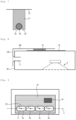
- the vent 5 has a cylindrical shape with an oblong section: the vent 5, when it is seen in section along a plane perpendicular to its longitudinal axis X, has an oblong shape.
- the outline 20 of the vent 5 has the shape of a rectangle whose widths are rounded and whose lengths are parallel to the length of the decoder box 1.
- This elongated shape of the section of the vent 5, rather than circular, makes it possible to reduce the diameter of the vent 5 in its smallest dimension (“width” of the vent 5), which reduces the depth of the decoder box 1 while increasing the contact surface between the vent 5 and the air for the same volume of air (at constant surface, the perimeter of the vent 5 is increased).
- This elongated shape therefore makes it possible to improve heat exchanges while reducing the size of the decoder box 1.
- the periphery of the vent 5 is provided with fins 21.
- the fins 21 extend from an internal surface 22 of the vent 5 and parallel to the longitudinal axis X of the vent 5. The fins 21 make it possible to further increase the contact surface with the air.
- the necessary increase in the dimensions of the vent 5 is relatively small, since the presence of the fins 21 has little influence on the section of the vent 5.
- the fins 21, however, make it possible to obtain a significant increase in the perimeter of the vent 5, and therefore in the exchange surface between the heat dissipation device 17 and the air.
- the air speed profile must be as uniform as possible in the section of the vent 5, at the inlet and outlet.
- the effective section of the vent 5 will be reduced and the resonance frequency of the bass reflex will no longer correspond to that which was calculated for the enclosure 2.
- the dimensions and position of the fins 21 should preferably be chosen so that the distance e between two adjacent fins 21 is greater than the height h of said fins 21.
- each fin 21 should preferably be chosen to be as small as possible, even if it has very little influence on increasing the perimeter of the vent 5. These criteria also make it possible to avoid acoustic disturbances when the air circulates at high speed between two fins 21 (such disturbances can generate whistling sounds).
- the height h of the fins 21 decreases as it approaches each of the ends 8, 9 of the vent 5.
- Each fin 21 comprises, along its length, a central portion of continuous height and two extreme portions whose height decreases towards the relevant end of the fin (and therefore of the vent).
- Each fin 21 is therefore profiled and becomes thinner at the inlet and outlet of the vent 5, which makes it possible to avoid turbulence.
- the chamfer thus formed makes it possible to prevent the fin 21 from acting as an obstacle to the flow of air.
- At least one of the fins 21 comprises a cable passage which extends along a length of said fin 21 and which makes it possible to accommodate a cable 23.
- Several fins 21 in this case each comprise a cable passage.
- the cables 23 here connect, for example, the loudspeaker 4 to an amplifier located outside the box 3.
- the cable(s) 23 could perfectly well connect components other than a loudspeaker and an amplifier.
- Each cable passage comprises in this case a groove 24 formed at the level of the upper surface 25 of the fin, that is to say of the surface opposite the internal surface 22 of the vent 5 from which said fin extends.
- the groove 24 allows the cable 23 to be inserted into the entire length of the vent 5.
- the groove 24 holds the cable 23 by pinching. This allows the cable 23 to pass through the vent 5, so as not to have to manage a passage of the cable 23 through the box and thus avoid sealing problems.
- the cable 23, smooth or rough, must be sufficiently flexible to fit into the groove 24 and be held there by force.
- the material of the vent 5 as mentioned above ensures that the fin 21 is sufficiently strong to hold the cable without deforming.
- the extension of the heat dissipation device 17 at the vent outlet 5 can be used to guide the cable 23 to the component located outside the box 3 and to which it is connected.
- the groove 24 here has a narrowing at its exit (and possibly at its entry), in order to eliminate the risks of the cable 23 “coming out” during normal use of the product.
- the presence of the groove 24 and of the cable 23 does not modify the formula for the resonant frequency of the vent 5 provided previously, which facilitates the dimensioning and design of the heat dissipation device 17.
- vent 5 could extend through another face of the box 3, and for example through the rear face 26.
- the component 16 to be cooled and the electrical card 15 on which it is mounted may be located on top of the box 3.
- the vent 5 is extended in its external part by a first plate 18a then by a second plate 18b perpendicular to the first plate 18a, the second plate 18b completely covering the surface of the component 16.
- the first plate 18a and the second plate 18b (and the vent 5) may be formed by a single part, but this is not necessarily the case.
- the plate(s) 18 could form a portion (or all) of one or more faces of the box 3.
- the height of the fins 21 can also be extended to have several pipes whose sum of sections is equal to the section of the initial vent.
- the enclosure 2 thus comprises a plurality of vents.
- vents can be "jointed” (for example by one of their walls), or can be non-jointed.
- the enclosure comprises four vents 5a, 5b, 5c, 5d.
- the longitudinal axes X of the vents 5 are parallel to each other and are perpendicular to the plane in which the plate 18 extends.
- each vent 5 along a plane perpendicular to its longitudinal axis X is oblong.
- the outline 20 of each vent 5 has the shape of a rectangle whose widths are rounded and whose lengths are parallel to the length of the decoder box 1.
- vents are aligned and extend successively so that the longitudinal axes Y of their contours 20 are aligned and parallel to the length of the decoder box 1.
- vents are positioned so that the outer walls of two adjacent vents are in contact at the width of their contour 20: vent 5a is in contact with vent 5b which is also in contact with vent 5c which is also in contact with vent 5d.
- This configuration makes it possible to maximize the exchange surfaces with the air.
- This variant can be used in the case where the installation of the fins 21 is too complex, for example if the material is too flexible or if the machining of fins is not possible.
- the electrical equipment in which the invention is implemented is not necessarily a decoder box, but can be any equipment comprising an acoustic speaker and electronic components: connected speaker, voice assistant, television, etc.
- dissipation plate 18 can be thermally coupled with several electronic components.
- the plate may optionally be fitted with ribs/fins to increase the dissipation surface.
- the plate and the component to be cooled could be located inside the box; in this case, the plate extends from the end 9 of the vent 5.
- the heat dissipation device could include two plates each extending from a separate end of the vent: one plate positioned outside the enclosure and another inside the enclosure, each plate being thermally coupled to at least one electronic component.
- the thermally conductive element which extends from one end of the vent, is not necessarily a plate but can be of any shape.
- the vent and the thermal conductive element can be designed as several separate parts, linked by a suitable thermal bond (direct contact or thermal bonding means, for example thermal pad). It is then possible to have different materials between these two parts, such as aluminum or copper for the heat sink, and ABS plastic for the vent. This allows to reduce the overall manufacturing cost compared to an all-metal solution (ABS plastic being easier to machine for complex shapes).
- the thermal medium that can thermally couple the component to be cooled and the thermally conductive element is not necessarily a pad: it could be, for example, thermal paste or even thermally conductive epoxy resin.
- the cable passage associated with a fin is not necessarily a groove. It could be, for example, a tubular conduit formed inside the fin, or fixing means such as hooks positioned on one face of the fin.
- the cable passage is not necessarily associated with a single fin.
- the cable passage may be formed on or in a (single) fin, or between two adjacent fins, the cable passage extending along a length of said fin(s).
- the cable passage may thus for example consist of two fins placed close together making it possible to pinch the cable between the two fins.
- the faces of these fins located on the cable insertion side may optionally be ribbed in order to help hold the cable.
Landscapes
- Engineering & Computer Science (AREA)
- Physics & Mathematics (AREA)
- Signal Processing (AREA)
- Acoustics & Sound (AREA)
- Microelectronics & Electronic Packaging (AREA)
- Thermal Sciences (AREA)
- Health & Medical Sciences (AREA)
- Otolaryngology (AREA)
- Multimedia (AREA)
- Cooling Or The Like Of Electrical Apparatus (AREA)
Claims (13)
- Ausrüstung (1) enthaltend:- eine Lautsprecherbox (2) umfassend einen Korpus (3), einen Lautsprecher (4) und eine Entlüftung (5);- eine elektronische Komponente (16);- eine Wärmeableitungsvorrichtung (17), welche derart angeordnet ist, dass sie eine von der elektronischen Komponente erzeugte Wärme ableitet, und welche die Entlüftung (5) sowie ein wärmeleitendes Element (18) umfasst, das sich von einem Ende (8) der Entlüftung aus erstreckt und mit der elektronischen Komponente thermisch verkoppelt ist, wobei die Entlüftung Rippen (21) umfasst, die sich von einer Innenfläche (22) der Entlüftung aus und parallel zu einer Längsachse (X) der Entlüftung erstrecken, wobei die Ausrüstung dadurch gekennzeichnet ist, dass sie ein Kabel (23) sowie einen Kabeldurchgang enthält, der an oder in einer Rippe bzw. zwischen zwei benachbarten Rippen ausgebildet ist, wobei sich der Kabeldurchgang entlang einer Länge der einen oder der mehreren Rippen erstreckt.
- Ausrüstung nach Anspruch 1, wobei das wärmeleitende Element eine Platte (18) umfasst, die sich in einer Ebene senkrecht zu einer Längsachse (X) der Entlüftung erstreckt, und wobei sich die Entlüftung an dem oben erwähnten Ende aufweitet und in die leitende Platte mündet.
- Ausrüstung nach Anspruch 2, wobei die elektronische Komponente auf einer elektrischen Leiterkarte (15) montiert ist, die sich zwischen der Platte und einer Fläche (6) des Korpus parallel zu der Platte und der Fläche erstreckt.
- Ausrüstung nach einem der vorhergehenden Ansprüche, wobei die Entlüftung (5) im Querschnitt entlang einer Ebene senkrecht zu einer Längsachse (X) der Entlüftung betrachtet eine längliche Form aufweist.
- Ausrüstung nach einem der Ansprüche 1 bis 4, wobei ein Abstand e zwischen zwei benachbarten Rippen (21) derart gewählt ist, dass:

- Ausrüstung nach einem der Ansprüche 1 bis 5, wobei eine Höhe aller Rippen (21) mit zunehmender Nähe zu den Enden (8, 9) der Entlüftung (5) abnimmt.
- Ausrüstung nach einem der Ansprüche 1 bis 6, wobei der Kabeldurchgang eine Nut (24) umfasst, die an einer Oberfläche (25) einer Rippe ausgebildet ist, wobei diese Oberfläche der Innenfläche (22) der Entlüftung abgewandt ist, von welcher aus sich die Rippe erstreckt.
- Ausrüstung nach Anspruch 7, wobei das Kabel (23) über die gesamte Länge der Entlüftung (5) hinweg in die Nut (24) eingesetzt ist, wobei das Kabel (23) durch Klemmung in der Nut (24) gehalten wird.
- Ausrüstung nach einem der vorhergehenden Ansprüche, umfassend eine Mehrzahl von Entlüftungen (5a, 5b, 5c, 5d) mit parallel verlaufenden Längsachsen (X).
- Ausrüstung nach Anspruch 9, wobei die Mehrzahl von Entlüftungen zumindest zwei Entlüftungen enthält, die jeweils eine Wand umfassen, welche mit einer Wand der anderen Entlüftung in Kontakt steht oder mit dieser zusammenfällt.
- Ausrüstung nach einem der vorhergehenden Ansprüche, wobei das wärmeleitende Element eine Platte umfasst, welche einen Teilabschnitt oder die Gesamtheit einer Fläche des Korpus bildet.
- Ausrüstung nach einem der vorhergehenden Ansprüche, wobei die thermische Verkopplung zwischen dem wärmeleitenden Element (18) und der elektronischen Komponente (16) durch ein thermisches Verbindungsmittel erzielt wird, das zwischen dem wärmeleitenden Element und der elektronischen Komponente (16) positioniert ist.
- Ausrüstung nach einem der vorhergehenden Ansprüche, wobei es sich bei der Ausrüstung um eine Decoderbox (1) handelt.
Applications Claiming Priority (1)
| Application Number | Priority Date | Filing Date | Title |
|---|---|---|---|
| FR2208968A FR3139695B1 (fr) | 2022-09-08 | 2022-09-08 | Event dissipateur thermique |
Publications (2)
| Publication Number | Publication Date |
|---|---|
| EP4336860A1 EP4336860A1 (de) | 2024-03-13 |
| EP4336860B1 true EP4336860B1 (de) | 2025-01-01 |
Family
ID=83996563
Family Applications (1)
| Application Number | Title | Priority Date | Filing Date |
|---|---|---|---|
| EP23194096.6A Active EP4336860B1 (de) | 2022-09-08 | 2023-08-29 | Wärmesenke-entlüftung |
Country Status (4)
| Country | Link |
|---|---|
| US (1) | US12309565B2 (de) |
| EP (1) | EP4336860B1 (de) |
| CN (1) | CN117677144B (de) |
| FR (1) | FR3139695B1 (de) |
Family Cites Families (11)
| Publication number | Priority date | Publication date | Assignee | Title |
|---|---|---|---|---|
| JPS571500Y2 (de) * | 1977-06-08 | 1982-01-11 | ||
| JPH10164680A (ja) * | 1996-11-28 | 1998-06-19 | Namco Ltd | スピーカボックス |
| JP2003061177A (ja) * | 2001-08-15 | 2003-02-28 | Sony Corp | バスレフ型スピーカキャビネットのダクト |
| US20060171556A1 (en) * | 2004-12-17 | 2006-08-03 | Galaxy Audio, Inc. | Cooling structure for loudspeaker driver |
| US8059856B2 (en) * | 2006-07-31 | 2011-11-15 | Peavey Electronics Corporation | Methods and apparatus for providing a heat sink for a loudspeaker |
| KR102489874B1 (ko) * | 2017-11-24 | 2023-01-18 | 삼성전자주식회사 | 방열 구조를 포함하는 전자 장치 |
| US10419855B2 (en) * | 2017-11-30 | 2019-09-17 | Apple Inc. | Cooling for audio appliances |
| FR3075546B1 (fr) * | 2017-12-19 | 2020-09-11 | Sagemcom Broadband Sas | Enceinte acoustique de type bass-reflex |
| CN112368665B (zh) * | 2018-10-08 | 2024-07-02 | 谷歌有限责任公司 | 显示助理设备中的扬声器组件 |
| DE102019108423B4 (de) * | 2019-04-01 | 2021-08-05 | Svetlomir Aleksandrov | Lautsprecherbox und Lautsprecher |
| US11521909B2 (en) * | 2019-10-14 | 2022-12-06 | Google Llc | Passive thermal-control system of an electronic speaker device and associated electronic speaker devices |
-
2022
- 2022-09-08 FR FR2208968A patent/FR3139695B1/fr active Active
-
2023
- 2023-08-29 EP EP23194096.6A patent/EP4336860B1/de active Active
- 2023-09-07 CN CN202311155951.1A patent/CN117677144B/zh active Active
- 2023-09-08 US US18/463,945 patent/US12309565B2/en active Active
Also Published As
| Publication number | Publication date |
|---|---|
| US20240098421A1 (en) | 2024-03-21 |
| EP4336860A1 (de) | 2024-03-13 |
| CN117677144A (zh) | 2024-03-08 |
| FR3139695A1 (fr) | 2024-03-15 |
| FR3139695B1 (fr) | 2025-09-05 |
| CN117677144B (zh) | 2025-11-18 |
| US12309565B2 (en) | 2025-05-20 |
Similar Documents
| Publication | Publication Date | Title |
|---|---|---|
| EP2770809B1 (de) | Elektronische Karte | |
| EP3410199B1 (de) | Optische vorrichtung für ein fahrzeug mit einem heizelement | |
| EP3917159B1 (de) | Schalltrichter für allgemeine lautsprecherbox | |
| EP2081422A1 (de) | Gehäuse aus stranggepressten Multipositions-Metallprofilen zur Herstellung einer dichten elektronischen Leistungsvorrichtung | |
| FR2919454A1 (fr) | Systeme de reproduction sonore a enceinte a events. | |
| FR3049160A1 (fr) | Dispositif electronique et methode d'assemblage d'un tel dispositif | |
| EP3328059A1 (de) | Kameravorrichtung eines kraftfahrzeugs, und montagemethode | |
| FR2867937A1 (fr) | Monture de module de haut parleur, module de haut-parleur associe et dispositif electronique avec un module de haut-parleur | |
| EP4336860B1 (de) | Wärmesenke-entlüftung | |
| FR3050862A1 (fr) | Dispositif electronique a puces electroniques et dissipateur de la chaleur | |
| EP4383748B1 (de) | Ausrüstung mit einem akustischen gehäuse mit mindestens einem verstärker | |
| EP3725090B1 (de) | Lautsprechergehäuse vom bassreflextyp | |
| FR3065135A1 (fr) | Enceinte acoustique | |
| EP4047945B1 (de) | Elektronisches gerät mit einer wasserdichten akustischen leitung | |
| WO2021130039A1 (fr) | Dispositif de dissipation de chaleur, système électrique comportant un tel dispositif et procédé de fabrication associé | |
| FR3013176A1 (fr) | Ensemble haut-parleur etanche pour forte profondeur | |
| FR3131971A1 (fr) | Caisson pour système acoustique, système acoustique et procédé de fabrication associés | |
| EP2932730B1 (de) | Elektronische vorrichtung mit einem belüfteten gehäuse zur aufnahme mindestens eines lautsprechers | |
| FR3135658A1 (fr) | Interface de raccordement de conduit d’air sur un boîtier. | |
| EP4451700A1 (de) | Dekodergehäuse mit reduzierter höhe | |
| WO2014083254A1 (fr) | Ensemble electronique comprenant un composant à faces de dissipation thermique multiple | |
| FR2830717A1 (fr) | Enceinte acoustique constituee d'un boitier dissipateur de chaleur | |
| EP4472372A1 (de) | Wärmeregelungsvorrichtung und elektronische vorrichtung dafür | |
| CA2364129A1 (fr) | Systeme de transmission des vibrations acoustiques du canal de basses frequences a une rangee de sieges d'une salle de cinema, a multiples sorties | |
| FR2978872A1 (fr) | Dispositif comportant un substrat portant au moins un composant electronique et une piece dans laquelle est menage un espace interieur apte a recevoir un fluide de refroidissement |
Legal Events
| Date | Code | Title | Description |
|---|---|---|---|
| PUAI | Public reference made under article 153(3) epc to a published international application that has entered the european phase |
Free format text: ORIGINAL CODE: 0009012 |
|
| STAA | Information on the status of an ep patent application or granted ep patent |
Free format text: STATUS: EXAMINATION IS IN PROGRESS |
|
| 17P | Request for examination filed |
Effective date: 20230829 |
|
| AK | Designated contracting states |
Kind code of ref document: A1 Designated state(s): AL AT BE BG CH CY CZ DE DK EE ES FI FR GB GR HR HU IE IS IT LI LT LU LV MC ME MK MT NL NO PL PT RO RS SE SI SK SM TR |
|
| GRAP | Despatch of communication of intention to grant a patent |
Free format text: ORIGINAL CODE: EPIDOSNIGR1 |
|
| STAA | Information on the status of an ep patent application or granted ep patent |
Free format text: STATUS: GRANT OF PATENT IS INTENDED |
|
| INTG | Intention to grant announced |
Effective date: 20240722 |
|
| RIC1 | Information provided on ipc code assigned before grant |
Ipc: H04R 1/06 20060101ALN20240712BHEP Ipc: H04R 9/02 20060101ALN20240712BHEP Ipc: H04R 1/02 20060101ALN20240712BHEP Ipc: H04R 1/28 20060101AFI20240712BHEP |
|
| RBV | Designated contracting states (corrected) |
Designated state(s): AL AT BE BG CH CY CZ DE DK EE ES FI FR GB GR HR HU IE IS IT LI LT LU LV MC ME MK MT NL NO PL PT RO RS SE SI SK SM TR |
|
| GRAS | Grant fee paid |
Free format text: ORIGINAL CODE: EPIDOSNIGR3 |
|
| GRAA | (expected) grant |
Free format text: ORIGINAL CODE: 0009210 |
|
| STAA | Information on the status of an ep patent application or granted ep patent |
Free format text: STATUS: THE PATENT HAS BEEN GRANTED |
|
| AK | Designated contracting states |
Kind code of ref document: B1 Designated state(s): AL AT BE BG CH CY CZ DE DK EE ES FI FR GB GR HR HU IE IS IT LI LT LU LV MC ME MK MT NL NO PL PT RO RS SE SI SK SM TR |
|
| REG | Reference to a national code |
Ref country code: GB Ref legal event code: FG4D Free format text: NOT ENGLISH |
|
| REG | Reference to a national code |
Ref country code: CH Ref legal event code: EP |
|
| REG | Reference to a national code |
Ref country code: DE Ref legal event code: R096 Ref document number: 602023001583 Country of ref document: DE |
|
| REG | Reference to a national code |
Ref country code: IE Ref legal event code: FG4D Free format text: LANGUAGE OF EP DOCUMENT: FRENCH |
|
| REG | Reference to a national code |
Ref country code: LT Ref legal event code: MG9D |
|
| REG | Reference to a national code |
Ref country code: NL Ref legal event code: MP Effective date: 20250101 |
|
| REG | Reference to a national code |
Ref country code: AT Ref legal event code: MK05 Ref document number: 1757529 Country of ref document: AT Kind code of ref document: T Effective date: 20250101 |
|
| PG25 | Lapsed in a contracting state [announced via postgrant information from national office to epo] |
Ref country code: NL Free format text: LAPSE BECAUSE OF FAILURE TO SUBMIT A TRANSLATION OF THE DESCRIPTION OR TO PAY THE FEE WITHIN THE PRESCRIBED TIME-LIMIT Effective date: 20250101 |
|
| PG25 | Lapsed in a contracting state [announced via postgrant information from national office to epo] |
Ref country code: FI Free format text: LAPSE BECAUSE OF FAILURE TO SUBMIT A TRANSLATION OF THE DESCRIPTION OR TO PAY THE FEE WITHIN THE PRESCRIBED TIME-LIMIT Effective date: 20250101 |
|
| PG25 | Lapsed in a contracting state [announced via postgrant information from national office to epo] |
Ref country code: PL Free format text: LAPSE BECAUSE OF FAILURE TO SUBMIT A TRANSLATION OF THE DESCRIPTION OR TO PAY THE FEE WITHIN THE PRESCRIBED TIME-LIMIT Effective date: 20250101 |
|
| PG25 | Lapsed in a contracting state [announced via postgrant information from national office to epo] |
Ref country code: ES Free format text: LAPSE BECAUSE OF FAILURE TO SUBMIT A TRANSLATION OF THE DESCRIPTION OR TO PAY THE FEE WITHIN THE PRESCRIBED TIME-LIMIT Effective date: 20250101 |
|
| PG25 | Lapsed in a contracting state [announced via postgrant information from national office to epo] |
Ref country code: IS Free format text: LAPSE BECAUSE OF FAILURE TO SUBMIT A TRANSLATION OF THE DESCRIPTION OR TO PAY THE FEE WITHIN THE PRESCRIBED TIME-LIMIT Effective date: 20250501 Ref country code: NO Free format text: LAPSE BECAUSE OF FAILURE TO SUBMIT A TRANSLATION OF THE DESCRIPTION OR TO PAY THE FEE WITHIN THE PRESCRIBED TIME-LIMIT Effective date: 20250401 |
|
| PG25 | Lapsed in a contracting state [announced via postgrant information from national office to epo] |
Ref country code: HR Free format text: LAPSE BECAUSE OF FAILURE TO SUBMIT A TRANSLATION OF THE DESCRIPTION OR TO PAY THE FEE WITHIN THE PRESCRIBED TIME-LIMIT Effective date: 20250101 |
|
| PG25 | Lapsed in a contracting state [announced via postgrant information from national office to epo] |
Ref country code: PT Free format text: LAPSE BECAUSE OF FAILURE TO SUBMIT A TRANSLATION OF THE DESCRIPTION OR TO PAY THE FEE WITHIN THE PRESCRIBED TIME-LIMIT Effective date: 20250502 Ref country code: LV Free format text: LAPSE BECAUSE OF FAILURE TO SUBMIT A TRANSLATION OF THE DESCRIPTION OR TO PAY THE FEE WITHIN THE PRESCRIBED TIME-LIMIT Effective date: 20250101 |
|
| PG25 | Lapsed in a contracting state [announced via postgrant information from national office to epo] |
Ref country code: BG Free format text: LAPSE BECAUSE OF FAILURE TO SUBMIT A TRANSLATION OF THE DESCRIPTION OR TO PAY THE FEE WITHIN THE PRESCRIBED TIME-LIMIT Effective date: 20250101 Ref country code: GR Free format text: LAPSE BECAUSE OF FAILURE TO SUBMIT A TRANSLATION OF THE DESCRIPTION OR TO PAY THE FEE WITHIN THE PRESCRIBED TIME-LIMIT Effective date: 20250402 |
|
| PG25 | Lapsed in a contracting state [announced via postgrant information from national office to epo] |
Ref country code: AT Free format text: LAPSE BECAUSE OF FAILURE TO SUBMIT A TRANSLATION OF THE DESCRIPTION OR TO PAY THE FEE WITHIN THE PRESCRIBED TIME-LIMIT Effective date: 20250101 |
|
| PG25 | Lapsed in a contracting state [announced via postgrant information from national office to epo] |
Ref country code: CZ Free format text: LAPSE BECAUSE OF FAILURE TO SUBMIT A TRANSLATION OF THE DESCRIPTION OR TO PAY THE FEE WITHIN THE PRESCRIBED TIME-LIMIT Effective date: 20250101 |
|
| PG25 | Lapsed in a contracting state [announced via postgrant information from national office to epo] |
Ref country code: SE Free format text: LAPSE BECAUSE OF FAILURE TO SUBMIT A TRANSLATION OF THE DESCRIPTION OR TO PAY THE FEE WITHIN THE PRESCRIBED TIME-LIMIT Effective date: 20250101 |
|
| REG | Reference to a national code |
Ref country code: DE Ref legal event code: R097 Ref document number: 602023001583 Country of ref document: DE |
|
| PG25 | Lapsed in a contracting state [announced via postgrant information from national office to epo] |
Ref country code: SM Free format text: LAPSE BECAUSE OF FAILURE TO SUBMIT A TRANSLATION OF THE DESCRIPTION OR TO PAY THE FEE WITHIN THE PRESCRIBED TIME-LIMIT Effective date: 20250101 |
|
| PG25 | Lapsed in a contracting state [announced via postgrant information from national office to epo] |
Ref country code: DK Free format text: LAPSE BECAUSE OF FAILURE TO SUBMIT A TRANSLATION OF THE DESCRIPTION OR TO PAY THE FEE WITHIN THE PRESCRIBED TIME-LIMIT Effective date: 20250101 |
|
| PGFP | Annual fee paid to national office [announced via postgrant information from national office to epo] |
Ref country code: DE Payment date: 20250724 Year of fee payment: 3 |
|
| PG25 | Lapsed in a contracting state [announced via postgrant information from national office to epo] |
Ref country code: IT Free format text: LAPSE BECAUSE OF FAILURE TO SUBMIT A TRANSLATION OF THE DESCRIPTION OR TO PAY THE FEE WITHIN THE PRESCRIBED TIME-LIMIT Effective date: 20250101 |
|
| PGFP | Annual fee paid to national office [announced via postgrant information from national office to epo] |
Ref country code: FR Payment date: 20250723 Year of fee payment: 3 |
|
| PG25 | Lapsed in a contracting state [announced via postgrant information from national office to epo] |
Ref country code: EE Free format text: LAPSE BECAUSE OF FAILURE TO SUBMIT A TRANSLATION OF THE DESCRIPTION OR TO PAY THE FEE WITHIN THE PRESCRIBED TIME-LIMIT Effective date: 20250101 |
|
| PG25 | Lapsed in a contracting state [announced via postgrant information from national office to epo] |
Ref country code: RO Free format text: LAPSE BECAUSE OF FAILURE TO SUBMIT A TRANSLATION OF THE DESCRIPTION OR TO PAY THE FEE WITHIN THE PRESCRIBED TIME-LIMIT Effective date: 20250101 |
|
| PG25 | Lapsed in a contracting state [announced via postgrant information from national office to epo] |
Ref country code: SK Free format text: LAPSE BECAUSE OF FAILURE TO SUBMIT A TRANSLATION OF THE DESCRIPTION OR TO PAY THE FEE WITHIN THE PRESCRIBED TIME-LIMIT Effective date: 20250101 |
|
| PLBE | No opposition filed within time limit |
Free format text: ORIGINAL CODE: 0009261 |
|
| STAA | Information on the status of an ep patent application or granted ep patent |
Free format text: STATUS: NO OPPOSITION FILED WITHIN TIME LIMIT |
|
| 26N | No opposition filed |
Effective date: 20251002 |
|
| PG25 | Lapsed in a contracting state [announced via postgrant information from national office to epo] |
Ref country code: MC Free format text: LAPSE BECAUSE OF FAILURE TO SUBMIT A TRANSLATION OF THE DESCRIPTION OR TO PAY THE FEE WITHIN THE PRESCRIBED TIME-LIMIT Effective date: 20250101 |
|
| PG25 | Lapsed in a contracting state [announced via postgrant information from national office to epo] |
Ref country code: LU Free format text: LAPSE BECAUSE OF NON-PAYMENT OF DUE FEES Effective date: 20250829 |