EP4337908B1 - Gewickelter wärmetauscher und verfahren - Google Patents
Gewickelter wärmetauscher und verfahren Download PDFInfo
- Publication number
- EP4337908B1 EP4337908B1 EP22726594.9A EP22726594A EP4337908B1 EP 4337908 B1 EP4337908 B1 EP 4337908B1 EP 22726594 A EP22726594 A EP 22726594A EP 4337908 B1 EP4337908 B1 EP 4337908B1
- Authority
- EP
- European Patent Office
- Prior art keywords
- annular channel
- channel
- heat exchanger
- liquid phase
- shell
- Prior art date
- Legal status (The legal status is an assumption and is not a legal conclusion. Google has not performed a legal analysis and makes no representation as to the accuracy of the status listed.)
- Active
Links
Images


Classifications
-
- F—MECHANICAL ENGINEERING; LIGHTING; HEATING; WEAPONS; BLASTING
- F28—HEAT EXCHANGE IN GENERAL
- F28D—HEAT-EXCHANGE APPARATUS, NOT PROVIDED FOR IN ANOTHER SUBCLASS, IN WHICH THE HEAT-EXCHANGE MEDIA DO NOT COME INTO DIRECT CONTACT
- F28D7/00—Heat-exchange apparatus having stationary tubular conduit assemblies for both heat-exchange media, the media being in contact with different sides of a conduit wall
- F28D7/02—Heat-exchange apparatus having stationary tubular conduit assemblies for both heat-exchange media, the media being in contact with different sides of a conduit wall the conduits being helically coiled
- F28D7/024—Heat-exchange apparatus having stationary tubular conduit assemblies for both heat-exchange media, the media being in contact with different sides of a conduit wall the conduits being helically coiled the conduits of only one medium being helically coiled tubes, the coils having a cylindrical configuration
-
- F—MECHANICAL ENGINEERING; LIGHTING; HEATING; WEAPONS; BLASTING
- F28—HEAT EXCHANGE IN GENERAL
- F28F—DETAILS OF HEAT-EXCHANGE AND HEAT-TRANSFER APPARATUS, OF GENERAL APPLICATION
- F28F9/00—Casings; Header boxes; Auxiliary supports for elements; Auxiliary members within casings
- F28F9/02—Header boxes; End plates
- F28F9/026—Header boxes; End plates with static flow control means, e.g. with means for uniformly distributing heat exchange media into conduits
- F28F9/027—Header boxes; End plates with static flow control means, e.g. with means for uniformly distributing heat exchange media into conduits in the form of distribution pipes
- F28F9/0275—Header boxes; End plates with static flow control means, e.g. with means for uniformly distributing heat exchange media into conduits in the form of distribution pipes with multiple branch pipes
-
- F—MECHANICAL ENGINEERING; LIGHTING; HEATING; WEAPONS; BLASTING
- F25—REFRIGERATION OR COOLING; COMBINED HEATING AND REFRIGERATION SYSTEMS; HEAT PUMP SYSTEMS; MANUFACTURE OR STORAGE OF ICE; LIQUEFACTION SOLIDIFICATION OF GASES
- F25J—LIQUEFACTION, SOLIDIFICATION OR SEPARATION OF GASES OR GASEOUS OR LIQUEFIED GASEOUS MIXTURES BY PRESSURE AND COLD TREATMENT OR BY BRINGING THEM INTO THE SUPERCRITICAL STATE
- F25J5/00—Arrangements of cold exchangers or cold accumulators in separation or liquefaction plants
- F25J5/002—Arrangements of cold exchangers or cold accumulators in separation or liquefaction plants for continuously recuperating cold, i.e. in a so-called recuperative heat exchanger
-
- F—MECHANICAL ENGINEERING; LIGHTING; HEATING; WEAPONS; BLASTING
- F28—HEAT EXCHANGE IN GENERAL
- F28D—HEAT-EXCHANGE APPARATUS, NOT PROVIDED FOR IN ANOTHER SUBCLASS, IN WHICH THE HEAT-EXCHANGE MEDIA DO NOT COME INTO DIRECT CONTACT
- F28D21/00—Heat-exchange apparatus not covered by any of the groups F28D1/00 - F28D20/00
- F28D2021/0019—Other heat exchangers for particular applications; Heat exchange systems not otherwise provided for
- F28D2021/0033—Other heat exchangers for particular applications; Heat exchange systems not otherwise provided for for cryogenic applications
-
- F—MECHANICAL ENGINEERING; LIGHTING; HEATING; WEAPONS; BLASTING
- F28—HEAT EXCHANGE IN GENERAL
- F28F—DETAILS OF HEAT-EXCHANGE AND HEAT-TRANSFER APPARATUS, OF GENERAL APPLICATION
- F28F25/00—Component parts of trickle coolers
- F28F25/02—Component parts of trickle coolers for distributing, circulating, and accumulating liquid
- F28F25/04—Distributing or accumulator troughs
Definitions
- the invention relates to a wound heat exchanger and a method for exchanging heat between a refrigerant and a medium by means of such a wound heat exchanger.
- Liquefied natural gas is the name given to processed natural gas that has been liquefied by cooling it to -161 °C to -164 °C. Liquefied natural gas has only a fraction of the volume of gaseous natural gas. Liquefied natural gas therefore has great advantages, particularly for transport and storage purposes. Liquefied natural gas can be transported as a liquid in suitable transport containers by road, rail or water.
- so-called coil wound heat exchangers can be used to liquefy natural gas.
- a wound heat exchanger comprises a shell and a tube bundle housed in the shell, through which the natural gas to be liquefied is passed.
- the tube bundle is sprayed with a liquid phase of a two-phase refrigerant, for example using a so-called ring channel distributor.
- ring channel distributors are described in the documents DE 10 2011 017030 A1 , WO 2006/021315 A1 and DE 10 2011 103583 A1 shown.
- Such an annular channel distributor comprises an annular channel running around the inside of the casing and distributors extending radially out of the annular channel, which distribute the liquid phase evenly over the tube bundle. Between the distributors, tubes, so-called braids, of the tube bundle are led up past the annular channel distributor to a tube sheet. The higher the annular channel, the further the tube sheet is from the tube bundle and the longer the tubes leading to the tube sheet must be. This can make the manufacture of the wound heat exchanger more difficult. This needs to be improved.
- the object of the present invention is to provide an improved wound heat exchanger.
- the wound heat exchanger for exchanging heat between a coolant and a medium.
- the wound heat exchanger comprises a jacket, a tube bundle arranged within the jacket through which the medium can flow, a first annular channel arranged within the jacket and encircling it for separating a liquid phase of the coolant from a gaseous phase of the coolant, a second annular channel arranged within the jacket and encircling it for evenly distributing the liquid phase over the tube bundle in order to exchange heat between the coolant and the medium, and a connecting channel which establishes a fluid connection between the first annular channel and the second annular channel in order to conduct the liquid phase from the first annular channel into the second annular channel, wherein the first annular channel and the second annular channel are arranged at a distance from one another when viewed along an axis of symmetry of the jacket.
- first ring channel and a second ring channel separated from the first ring channel are provided, it is possible to design the first ring channel and the second ring channel with different widths. This makes production easier and can also lead to a reduction in the build-up of the liquid phase in the ring channels.
- the first ring channel can also be used to pre-separate the liquid phase and the gaseous phase of the coolant.
- the wound heat exchanger is in particular a so-called coil wound heat exchanger (CWHE).
- the wound heat exchanger is preferably suitable for liquefying natural gas.
- the medium can be natural gas.
- the wound heat exchanger can also be used for liquefying any other media than natural gas.
- the tube bundle is in particular wound in multiple layers on a core tube arranged centrally in the jacket.
- the jacket preferably comprises a hollow cylindrical base section, which can be constructed rotationally symmetrically to the axis of symmetry, a cover section that closes off the base section at the top, and a base section that closes off the base section at the bottom.
- the axis of symmetry can also be referred to as the central axis.
- the jacket is in particular fluid-tight.
- the tube bundle comprises a tube side and a shell side.
- the "tube side” in this case is understood to mean an interior space enclosed by tubes of the tube bundle through which the medium to be liquefied is passed. The medium is thus fed into the tubes of the tube bundle.
- the fact that the medium is "fed” into the tube bundle is to be understood in particular as meaning that the medium is introduced into the tubes of the tube bundle.
- several different fractions or pipe streams can flow through the tube bundle.
- One of the fractions can be the medium.
- Another of the fractions can be part of the coolant.
- Other fractions can include, for example, other coolants, process media or the like.
- the coolant can also be fed into the tube bundle and passed through the tube bundle on the tube side.
- the tube bundle therefore has tubes through which only the medium flows. Other tubes are only flowed through by the coolant. Furthermore, other tubes can also be provided through which other fractions flow.
- the aforementioned different tubes can form different layers of the tube bundle.
- shell side means an area outside the tubes of the tube bundle.
- the coolant flows through the tube bundle.
- a large number of gaps or passages lead through the tube bundle, through which the coolant is passed in order to extract heat from the tube bundle, in particular from the medium.
- heat is preferably extracted from the medium, which the coolant absorbs.
- the coolant can at least partially evaporate.
- the coolant can also evaporate completely. After flowing around or through the tube bundle on the shell side, the completely or partially evaporated coolant can be extracted from the shell.
- the refrigerant can be ethane, for example. However, any other refrigerant can also be used.
- a refrigerant is suitable for transporting enthalpy from a cooled product, in this case the medium, to an environment.
- the difference to a coolant is that a refrigerant can carry out this heat transport in a refrigeration circuit along a temperature gradient, so that by using added energy, the ambient temperature can even be higher than the temperature of the medium to be cooled, while a coolant is only able to transport the enthalpy in a cooling circuit against the temperature gradient to a place with a lower temperature.
- the medium is natural gas
- the liquefied medium or natural gas can be referred to as liquefied natural gas (LNG).
- the first ring channel can also be referred to as the upper ring channel, since it is arranged above the second ring channel with respect to a direction of gravity. Accordingly, the second ring channel can be referred to as the lower ring channel.
- the fact that the first ring channel "runs around" the casing means in this case that the first ring channel preferably runs completely around the axis of symmetry and thus forms a ring-shaped geometry.
- the first ring channel can be continuous. Alternatively, it is also possible for the first ring channel to be divided into several separate ring segments. The same applies to the second ring channel.
- the first ring channel and the second ring channel are two separate components that are arranged at a certain distance from one another when viewed along the axis of symmetry.
- the connecting channel can be a pipe, a shaft, a hose or the like. With the help of the connecting channel, the liquid medium is guided from the first ring channel into the second ring channel.
- the connecting channel is a downpipe or can be referred to as a downpipe. Any number of connecting channels can be provided.
- the connecting channel can have a circular or any other cross-section.
- the second ring channel is suitable for distributing the liquid phase of the coolant evenly over the tube bundle.
- the second ring channel can comprise distributors, which will be explained later. These distributors are in particular part of the second ring channel.
- the second ring channel itself can also have openings, holes or the like, which enable the tube bundle to be evenly sprinkled with the liquid phase of the coolant.
- the second ring channel can also be referred to as a ring channel distributor.
- the first ring channel is suitable for separating the liquid phase of the refrigerant from the gaseous phase of the refrigerant.
- the separation takes place in that the liquid phase is drawn downwards towards the second ring channel with the help of the connecting channel and the gaseous phase of the refrigerant exits upwards from the first ring channel.
- the refrigerant is two-phase and can have the liquid phase and the gaseous phase.
- the liquid phase can change into the gaseous phase and vice versa.
- the liquid phase of the refrigerant changes at least partially from the liquid phase to the gaseous phase when it flows through or around the tube bundle.
- the evaporating refrigerant absorbs heat from the medium.
- the second annular channel comprises a plurality of distributors for uniformly distributing the liquid phase onto the tube bundle, wherein the distributors extend radially toward the axis of symmetry further into the shell than the second annular channel.
- the number of distributors is basically arbitrary. For example, three distributors or six distributors are provided.
- the distributors are placed evenly spaced from one another around the axis of symmetry.
- the distributors protrude radially from the second ring channel into the casing and thus partially cover the tube bundle from above.
- the distributors are in particular part of the second ring channel and are in fluid communication with it.
- the fact that the distributors are "in fluid communication" with the second ring channel means in particular that the liquid phase of the coolant can flow from the second ring channel into the distributors.
- the distributors preferably each have a large number of openings, openings, bores or the like arranged on the underside, which enable the tube bundle to be evenly sprinkled with the liquid phase of the coolant.
- the distributors are evenly distributed around the axis of symmetry, with a gap being provided between each two adjacent distributors.
- the number of gaps preferably corresponds to the number of distributors.
- the distributors and the gaps are arranged alternately, so that there is a gap between two distributors and a distributor between two gaps.
- the wound heat exchanger further comprises a plurality of connecting channels, wherein each distributor is assigned a connecting channel.
- connection channels are the same. For example, three or six connection channels are provided.
- the connecting channel runs parallel to the axis of symmetry.
- the connecting channel runs along the direction of gravity.
- the connecting channel or channels parallel to the axis of symmetry, the shortest possible connection between the first ring channel and the second ring channel can be achieved.
- the connecting channels open out of a base of the first ring channel.
- first annular channel and the second annular channel extend radially onto the axis of symmetry to different distances into the casing.
- first ring channel and the second ring channel extend radially to different distances into an interior space enclosed by the casing.
- the first ring channel has a first inner diameter.
- the second ring channel has a second inner diameter.
- the inner diameters can be of different sizes, so that the first ring channel and the second ring channel extend into the casing to different distances.
- the first inner diameter of the first ring channel and the second inner diameter of the second ring channel can also be the same size.
- the second ring channel projects radially towards the axis of symmetry further into the casing than the first ring channel.
- the second ring channel is wider than the first ring channel. This facilitates the manufacture of the wound heat exchanger.
- the first ring channel is arranged above the second ring channel when viewed along a direction of gravity.
- the first ring channel can therefore also be referred to as the upper ring channel and the second ring channel as the lower ring channel.
- the second ring channel is placed below the first ring channel when viewed along the direction of gravity.
- the wound heat exchanger further comprises a tube sheet which is in fluid communication with tubes of the tube bundle, wherein the tube sheet is arranged between the first annular channel and the second annular channel when viewed along the axis of symmetry.
- the tube sheet is placed below the first ring channel and above the second ring channel when viewed along the direction of gravity.
- Several tube sheets can be provided.
- the number of tube sheets corresponds to the number of distributors. Twice as many tube sheets as distributors can also be provided. Because the tube sheet is arranged between the first ring channel and the second ring channel, it is possible to shorten the tubes pulled upwards from the tube bundle compared to a wound heat exchanger with only one ring channel. This makes it easier to manufacture the wound heat exchanger.
- the tubes pulled upwards can also be referred to as "braids". A reduction in the "braid length" can thus be achieved.
- the first ring channel and/or the second ring channel each run completely around the axis of symmetry.
- first ring channel and/or the second ring channel each have a circumferential angle of 360°.
- first ring channel and/or the second ring channel it is also possible in principle for the first ring channel and/or the second ring channel to be divided into several separate ring channel segments.
- first annular channel and/or the second annular channel are each open in the direction of a cover section of the casing.
- first ring channel and/or the second ring channel are open at the top. This allows the gaseous phase of the refrigerant to exit upwards from the respective ring channel.
- the heat exchanger comprises a casing, a tube bundle arranged inside the casing, a first ring channel arranged inside the casing and encircling it, a second ring channel arranged inside the casing and encircling it, and a connecting channel which establishes a fluid connection between the first ring channel and the second ring channel, wherein the first ring channel and the second ring channel are arranged at a distance from one another when viewed along an axis of symmetry of the casing.
- the method comprises the following steps: a) flowing the medium through the tube bundle, b) separating a liquid phase of the coolant from a gaseous phase of the coolant using the first ring channel, c) guiding the liquid phase into the second ring channel using the connecting channel, and d) evenly distributing the liquid phase over the tube bundle using the second ring channel in order to exchange heat between the coolant and the medium.
- Steps a) to d) can be carried out simultaneously.
- heat is extracted from the medium with the help of the coolant.
- the coolant can at least partially evaporate and pass into the gaseous phase.
- the medium can be liquefied or at least cooled.
- the medium flows through the tube bundle, in particular on the tube side.
- the liquid phase is distributed over the tube bundle, in particular on the shell side.
- step d) the liquid phase is evenly distributed over the tube bundle by means of several distributors of the second annular channel.
- the number of distributors is arbitrary. By providing several distributors, a particularly even distribution of the liquid phase can be achieved.
- the distributors are preferably part of the second ring channel.
- step d) the liquid phase is dammed up in the second annular channel such that the connecting channel opens into the second annular channel below a liquid level of the liquid phase in the latter.
- a lower edge of the connecting channel is arranged below the liquid level.
- the connecting channel is thus immersed or submerged in the liquid phase.
- step b) the liquid phase is withdrawn downwards from the first ring channel with the aid of the connecting channel, viewed along a direction of gravity, wherein the gaseous phase exits upwards from the first ring channel, viewed along the direction of gravity.
- the gaseous phase can be removed from the shell at the cover section.
- the liquid phase of the refrigerant that is exiting downwards from the tube bundle and has not evaporated can also be removed from the shell.
- wound heat exchanger and/or the method also include combinations not explicitly mentioned above or in the The following features or embodiments described with respect to the exemplary embodiments.
- the person skilled in the art will also add individual aspects as improvements or additions to the respective basic form of the wound heat exchanger and/or the method.
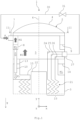
- the Fig. 1 shows a schematic sectional view of an embodiment of a coil wound heat exchanger 1 (CWHE).
- the Fig. 2 shows a schematic sectional view of the wound heat exchanger 1. The following is the Fig. 1 and 2 simultaneously referred to.
- Such a wound heat exchanger 1 can be used to liquefy natural gas (LNG). However, other gases can also be liquefied.
- LNG natural gas
- the wound heat exchanger 1 is referred to below simply as a heat exchanger.
- the heat exchanger 1 comprises a casing 2.
- the casing 2 is constructed from a cylindrical base section 3, a dome-shaped curved cover section 4 and a dome-shaped curved bottom section (not shown). With respect to a direction of gravity g, the cover section 4 is placed above the bottom section.
- the base section 3, the cover section 4 and the bottom section are soldered, welded, screwed or riveted to one another.
- the casing 2 is fluid-tight.
- the casing 2 encloses an interior space 5.
- the casing 2 can be made of an aluminum alloy or a steel alloy.
- the casing 2 is essentially rotationally symmetrical to a central or symmetry axis 6. "Essentially" means that the casing 2 does not necessarily have to have a circular cross-section.
- the casing 2 can also be slightly oval or elliptical in cross-section.
- the casing 2 is positioned upright or vertically. This means that the symmetry axis 6 runs parallel to the direction of gravity g.
- the heat exchanger 1 is assigned a coordinate system with a width direction or x-direction x, a height direction or y-direction y and a depth direction or z-direction z.
- the directions x, y, z are oriented perpendicular to each other.
- the z-direction z is oriented parallel to the direction of gravity g and parallel to the axis of symmetry 6.
- An inlet nozzle 7 is provided on the base section 3 and is oriented perpendicular to the axis of symmetry 6.
- a coolant K for example ethane, can be supplied to the heat exchanger 1 via the inlet nozzle 7.
- the coolant K can be two-phase, so that it has a liquid phase KL and a gaseous phase KG.
- Several inlet nozzles 7 can be provided.
- the refrigerant K is in the Fig. 1 and 2 represented by block arrows.
- Block arrows with diagonal hatching represent a two-phase state of the refrigerant K.
- Horizontally hatched block arrows represent the gaseous phase KG of the refrigerant K.
- Unhatched block arrows represent the liquid phase KL of the refrigerant K.
- the coolant K can be fed into an upper or first ring channel 8 via the inlet connection 7.
- the first ring channel 8 can be rectangular in cross-section.
- the first ring channel 8 is arranged inside the casing 2.
- the first ring channel 8 runs completely around the axis of symmetry 6, so that the first ring channel 8 has a closed ring-shaped geometry. In principle, however, the first ring channel 8 can also be divided into several ring segments.
- the first ring channel 8 has an inner diameter d8.
- the first ring channel 8 is open at the top, i.e. in the direction of the cover section 4, so that the gaseous phase KG can exit upwards from the first ring channel 8 against the direction of gravity g.
- the gaseous phase KG can be withdrawn from the casing 2, for example, using an extraction nozzle provided on the cover section 4. Alternatively, the gaseous phase KG can be withdrawn downwards together with the liquid phase KL.
- the first ring channel 8 projects radially, i.e. in the direction of the axis of symmetry 6, into the casing 2, in particular into the interior 5.
- a liquid level 9 of the liquid phase KL is established in the first ring channel 8.
- the first ring channel 8 serves to separate the gaseous phase KG from the liquid phase KL. The separation takes place in that the gaseous phase KG, as previously mentioned, can escape upwards from the first ring channel 8 and the liquid phase KL is drawn downwards, i.e. in the direction of gravity g, from the first ring channel 8 with the aid of a connecting channel 10.
- the connecting channel 10 runs parallel to the direction of gravity g or parallel to the axis of symmetry 6.
- the connecting channel 10 can be a shaft, a pipe or the like.
- several connecting channels 10 to 12 are provided.
- the number of connecting channels 10 to 12 is basically arbitrary. For example, three or six connecting channels 10 to 12 are provided.
- the connecting channels 10 to 12 are arranged evenly distributed around the axis of symmetry 6. However, only one connecting channel 10 will be discussed below.
- the connecting channel 10 directs the liquid phase KL from the first ring channel 8 into a lower or second ring channel 13.
- the second ring channel 13 is arranged at a distance from the first ring channel 8.
- the first ring channel 8 is placed above the second ring channel 13 and the second ring channel 13 is placed below the first ring channel 8.
- the second ring channel 13 can, like the first ring channel 8, be rectangular in cross-section.
- the second ring channel 13 is arranged within the casing 2.
- the second ring channel 13 runs completely around the axis of symmetry 6, so that the second ring channel 13 has a closed ring-shaped geometry. In principle, however, the second ring channel 13 can also be divided into several ring segments.
- the second ring channel 13 has an inner diameter d13.
- the inner diameter d13 can be smaller than the inner diameter d8.
- the inner diameters d8, d13 can also be the same size.
- the inner diameter d8 can also be smaller than the inner diameter d13.
- the second ring channel 13 is open upwards, i.e. in the direction of the cover section 4, so that the gaseous phase KG can exit upwards from the second ring channel 13 against the direction of gravity g.
- the second ring channel 13 projects radially, i.e. in the direction of the axis of symmetry 6, into the casing 2, in particular into the interior 5.
- the second ring channel 13 preferably projects further into the casing 2 than the first ring channel 8.
- a liquid level 14 of the liquid phase KL is established in the second ring channel 13.
- the connecting channel 10 is immersed in the liquid phase so that a lower edge of the connecting channel 10 is positioned below the liquid level 14 when viewed along the direction of gravity g.
- the second ring channel 13 serves to evenly distribute the liquid phase KL to several distributors 15 to 17.
- the distributors 15 to 17 are part of the second ring channel 13.
- the number of distributors 15 to 17 is arbitrary. For example, three or six distributors 15 to 17 are provided. Preferably, the number of distributors 15 to 17 corresponds to the number of connecting channels 10 to 12. Each distributor 15 to 17 can be assigned a connecting channel 10 to 12. The distributors 15 to 17 are arranged evenly distributed around the axis of symmetry 6 or around a circumference of the casing 2.
- the distributors 15 to 17 can be designed as ring segments. However, this is not absolutely necessary. In this case, a "ring segment” is understood to mean a section of a ring.
- the distributors 15 to 17 are arranged alternately with spaces 18 to 20. This means that between two adjacent distributors 15 to 17 there is a space 18 to 20 and between two spaces 18 to 20 there is a distributor 15 to 17. In the following, only one distributor 15 is discussed.
- the distributor 15 points radially in the direction of the axis of symmetry 6 further into the casing 2, in particular into the interior space 5, than the second ring channel 13.
- the distributor 15 is in fluid communication with the second ring channel 13.
- "fluid communication” means in particular that the liquid phase KL can flow from the second ring channel 13 into the distributor 15.
- a breakthrough, an opening or the like can be provided in a base of the second ring channel 13.
- the distributor 15 is closed at the top, i.e. in the direction of the cover section 4.
- the liquid phase KL can exit from the distributor 15 at the bottom, i.e. facing away from the cover section 4.
- the distributor 15 has a large number of outlet openings, openings, bores or the like on the underside, with the aid of which the liquid phase KL can be evenly distributed.
- the heat exchanger 1 further comprises a tube bundle 21 arranged within the casing 2, which is sprayed with the liquid phase KL using the distributors 15 to 17.
- the liquid phase KL is evaporated in particular using a falling film.
- the tube bundle 21 is wound onto a core tube 22, which is placed centrally in the casing 2.
- the tube bundle 21 comprises a large number of tubes which are wound onto the core tube 22 in multiple layers.
- the tube bundle 21 comprises slots or gaps so that the liquid phase KL can flow through the tube bundle 21 on the casing side. In this case, "on the casing side” is to be understood as an area outside the tubes of the tube bundle 21.
- the tube bundle 21 completely fills an annular gap 23 provided between the core tube 22 and the casing 2.
- fractions or pipe flows can be guided through the tube bundle 21 on the pipe side.
- One of the fractions can be a medium to be liquefied, for example natural gas.
- Another of the fractions can be the liquid phase KL of the coolant K.
- Other fractions can include, for example, other coolants, process media or the like. This means that the coolant K can also be fed into the tube bundle 21 and guided through the tube bundle 21 on the pipe side. However, no direct contact and thus no mixing of the fractions in the tube bundle 21 is possible.
- the tube bundle 21 thus has tubes through which only the medium flows. Other tubes are only flowed through by the coolant K. Furthermore, other tubes can also be provided through which other fractions flow.
- the aforementioned different tubes can form different layers of the tube bundle 21.
- the "tube side" is understood here to mean an interior space enclosed by the tubes of the tube bundle 21, through which the medium to be liquefied, the coolant K and/or other fractions are passed.
- Individual tubes 24 to 26 are pulled from the tube bundle 21 through the gaps 18 to 20 upwards in the direction of the cover section 4.
- the tubes 24 to 26 run parallel to the axis of symmetry 6.
- the tubes 24 to 26 can also be referred to as "braids".
- the tubes 24 to 26 are fed to a tube plate 27.
- Preferably, several tube plates 27 to 29 are provided.
- the number of tube plates 27 to 29 can correspond to the number of distributors 15 to 17. However, this is not absolutely necessary. For example, twice as many tube plates 27 to 29 as distributors 15 to 17 can be provided.
- the tube plates 27 to 29 can be placed at different heights. This means that the tube plates 27 to 29 can be arranged offset from one another when viewed along the axis of symmetry 6. However, the tube plates 27 to 29 can also all be arranged at the same height. The tube plates 27 to 29 can be assigned to different tube flows or fractions of the tube bundle 21.
- the tube sheets 27 to 29 are welded or soldered into the shell 2.
- the tube sheets 27 to 29 can also be connected to the shell 2 using nozzles (not shown).
- the tube plates 27 to 29 can be arranged evenly distributed around the axis of symmetry 6. However, this is not absolutely necessary.
- the tube plates 27 to 29 can also be arranged unevenly distributed around the axis of symmetry 6. At least one tube plate 27 to 29 can be assigned to each intermediate space 18 to 20. However, this is not absolutely necessary. Only one tube plate 27 is discussed below.
- the tube sheet 27 is in fluid communication with the inlet nozzle 7 via a supply line 30 and an expansion valve 31.
- tubes of the tube bundle 21, through which the coolant K is fed on the tube side are in fluid communication with the inlet nozzle 7 via the tube sheet 27 and the supply line 30.
- the expansion valve 31 is a so-called Joule-Thomson valve.
- the coolant K flowing through the tube bundle 21 is returned to the inlet nozzle 7 via the supply line 30. This is under a higher pressure than the interior 5 of the jacket 2.
- the coolant K is expanded in the expansion valve 31 and fed to the inlet nozzle 7 as a two-phase flow. During the expansion, expansion cold is created, which cools the coolant K.
- the tube bundle 21 is then cooled again with this "colder" coolant K.
- the tubes 24 to 26 are in fluid communication with the tube sheet 27.
- the tube sheet 27 is placed between the first ring channel 8 and the second ring channel 13, viewed along the axis of symmetry 6. In particular, the tube sheet 27 is placed below the first ring channel 8 and above the second ring channel 13.
- the functionality of the heat exchanger 1 is explained below.
- the medium to be liquefied flows through the tube bundle 21 on the tube side.
- the two-phase refrigerant K is fed to the first ring channel 8 via the inlet connection 7.
- the liquid phase KL is separated from the gaseous phase KG by withdrawing the liquid phase KL downwards into the second ring channel 13 using the connecting channels 10 to 12 and the gaseous phase KG escaping upwards.
- the gaseous phase KG can be withdrawn upwards or downwards.
- the gaseous phase KG can be withdrawn downwards together with the liquid phase KL, flowing through the tube bundle 21.
- the second ring channel 13 distributes the liquid phase KL evenly to the distributors 15 to 17, which in turn spray the tube bundle 21 with the liquid phase KL.
- the liquid phase KL flows through the tube bundle 21 on the shell side, whereby the liquid phase KL at least partially evaporates. In the process, heat is extracted from the medium.
- the medium liquefies in the process.
- the evaporated liquid phase KL rises upwards as the gaseous phase KG and can be withdrawn upwards. Alternatively, the gaseous phase KG can also be withdrawn downwards through the tube bundle 21.
- the liquid phase KL that does not evaporate flows out of the tube bundle 21 on the underside and can be withdrawn downwards.
- the Fig. 3 shows a schematic block diagram of an embodiment of a method for exchanging heat between the coolant K and the medium using the wound heat exchanger 1.
- the medium flows through the tube bundle 21.
- the liquid phase KL of the coolant K is separated from the gaseous phase KG using the first ring channel 8.
- a step S3 the liquid phase KL is guided into the second ring channel 13 using the connecting channels 10 to 12.
- the liquid phase KL is evenly distributed over the tube bundle 21 using the distributors 15 to 17 in order to exchange the heat between the coolant K and the medium. Steps S1 to S4 can be carried out simultaneously.
Landscapes
- Engineering & Computer Science (AREA)
- Physics & Mathematics (AREA)
- Thermal Sciences (AREA)
- Mechanical Engineering (AREA)
- General Engineering & Computer Science (AREA)
- Heat-Exchange Devices With Radiators And Conduit Assemblies (AREA)
Description
- Die Erfindung betrifft einen gewickelten Wärmetauscher und ein Verfahren zum Austausch von Wärme zwischen einem Kältemittel und einem Medium mit Hilfe eines derartigen gewickelten Wärmetauschers.
- Als Flüssigerdgas (Engl.: Liquefied Natural Gas, LNG) wird durch Abkühlung auf -161 °C bis -164 °C verflüssigtes aufbereitetes Erdgas bezeichnet. Flüssigerdgas weist nur einen Bruchteil des Volumens von gasförmigem Erdgas auf. Besonders zu Transport- und Lagerungszwecken hat Flüssigerdgas daher große Vorteile. Das Flüssigerdgas kann als Flüssigkeit in geeigneten Transportbehältern auf der Straße, der Schiene oder auf dem Wasser transportiert werden.
- Zur Verflüssigung des Erdgases können gemäß betriebsinternen Erkenntnissen sogenannte Coil Wound Heat Exchanger (CWHE) oder gewickelte Wärmetauscher eingesetzt werden. Ein derartiger gewickelter Wärmetauscher umfasst einen Mantel sowie ein in dem Mantel aufgenommenes Rohrbündel, durch welches das zu verflüssigende Erdgas geleitet wird. Das Rohrbündel wird beispielsweise mit Hilfe eines so genannten Ringkanalverteilers mit einer flüssigen Phase eines zweiphasigen Kältemittels beregnet. Beispielhafte Ringkanalverteiler sind in den Dokumenten
DE 10 2011 017030 A1 ,WO 2006/021315 A1 undDE 10 2011 103583 A1 gezeigt. - Ein derartiger Ringkanalverteiler umfasst einen innenseitig um den Mantel umlaufenden Ringkanal und sich radial aus dem Ringkanal heraus erstreckende Verteiler, welche die flüssige Phase gleichmäßig auf das Rohrbündel verteilen. Zwischen den Verteilern werden Rohre, sogenannte Zöpfe, des Rohrbündels an dem Ringkanalverteiler vorbei nach oben zu einem Rohrboden geführt. Je höher der Ringkanal ist, desto weiter ist der Rohrboden von dem Rohrbündel beabstandet und desto länger müssen die zu dem Rohrboden geführten Rohre sein. Dies kann die Fertigung des gewickelten Wärmetauschers erschweren. Dies gilt es zu verbessern.
- Vor diesem Hintergrund besteht die Aufgabe der vorliegenden Erfindung darin, einen verbesserten gewickelten Wärmetauscher zur Verfügung zu stellen.
- Demgemäß wird ein gewickelter Wärmetauscher zum Austausch von Wärme zwischen einem Kältemittel und einem Medium vorgeschlagen. Der gewickelte Wärmetauscher umfasst einen Mantel, ein innerhalb des Mantels angeordnetes Rohrbündel, das von dem Medium durchströmbar ist, einen innerhalb des Mantels angeordneten und um diesen umlaufenden ersten Ringkanal zum Trennen einer flüssigen Phase des Kältemittels von einer gasförmigen Phase des Kältemittels, einen innerhalb des Mantels angeordneten und um diesen umlaufenden zweiten Ringkanal zum gleichmäßigen Verteilen der flüssigen Phase auf das Rohrbündel, um die Wärme zwischen dem Kältemittel und dem Medium auszutauschen, und einen Verbindungskanal, der eine Fluidverbindung zwischen dem ersten Ringkanal und dem zweiten Ringkanal herstellt, um die flüssige Phase aus dem ersten Ringkanal in den zweiten Ringkanal zu leiten, wobei der erste Ringkanal und der zweite Ringkanal entlang einer Symmetrieachse des Mantels betrachtet voneinander beabstandet angeordnet sind.
- Dadurch, dass ein erster Ringkanal und ein von dem ersten Ringkanal getrennter zweiter Ringkanal vorgesehen ist, ist es möglich, den ersten Ringkanal und den zweiten Ringkanal unterschiedlich breit auszuführen. Dies erleichtert zum einen die Fertigung und kann zum anderen zu einer Reduktion eines Aufstaus der flüssigen Phase in den Ringkanälen führen. Es kann ferner mit Hilfe des ersten Ringkanals eine Vortrennung der flüssigen Phase und der gasförmigen Phase des Kältemittels erzielt werden.
- Der gewickelte Wärmetauscher ist insbesondere ein sogenannter Coil Wound Heat Exchanger (CWHE). Der gewickelte Wärmetauscher ist bevorzugt zum Verflüssigen von Erdgas geeignet. Das heißt, dass das Medium Erdgas sein kann. Der gewickelte Wärmetauscher kann jedoch auch zur Verflüssigung von beliebigen anderen Medien als Erdgas eingesetzt werden. Das Rohrbündel ist insbesondere mehrlagig auf ein mittig in dem Mantel angeordnetes Kernrohr aufgewickelt. Der Mantel umfasst vorzugsweise einen hohlzylinderförmigen Basisabschnitt, der rotationssymmetrisch zu der Symmetrieachse aufgebaut sein kann, einen den Basisabschnitt nach oben hin abschließenden Deckelabschnitt sowie einen den Basisabschnitt nach unten hin abschließenden Bodenabschnitt. Die Symmetrieachse kann auch als Mittelachse bezeichnet werden. Der Mantel ist insbesondere fluiddicht.
- Das Rohrbündel umfasst eine Rohrseite und eine Mantelseite. Unter der "Rohrseite" ist vorliegend ein von Rohren des Rohrbündels umschlossener Innenraum zu verstehen, durch welchen das zu verflüssigende Medium geleitet wird. Das Medium wird somit in die Rohre des Rohrbündels eingespeist. Darunter, dass das Medium in das Rohrbündel "eingespeist" wird, ist insbesondere zu verstehen, dass das Medium in die Rohre des Rohrbündels eingeleitet wird. Rohrseitig können mehrere unterschiedliche Fraktionen oder Rohrströme durch das Rohrbündel strömen. Eine der Fraktionen kann das Medium sein. Eine andere der Fraktionen kann ein Teil des Kältemittels sein. Weitere Fraktionen können beispielsweise andere Kältemittel, Prozessmedien oder dergleichen umfassen.
- Das heißt, auch das Kältemittel kann in das Rohrbündel eingespeist und rohrseitig durch das Rohrbündel geleitet werden. Es ist jedoch kein direkter Kontakt und damit auch keine Vermischung der Fraktionen in dem Rohrbündel möglich. Das Rohrbündel weist somit Rohre auf, die nur von dem Medium durchströmt werden. Weitere Rohre werden nur von dem Kältemittel durchströmt. Ferner können auch weitere Rohre vorgesehen sein, die von weiteren Fraktionen durchströmt werden. Die vorgenannten unterschiedlichen Rohre können unterschiedliche Schichten des Rohrbündels bilden.
- Unter "mantelseitig" ist vorliegend ein Bereich außerhalb der Rohre des Rohrbündels zu verstehen. Mantelseitig strömt das Kältemittel durch das Rohrbündel hindurch. Durch das Rohrbündel führt eine Vielzahl von Spalten oder Passagen, durch welche das Kältemittel hindurchgeleitet wird, um Wärme aus dem Rohrbündel, insbesondere aus dem Medium, zu entziehen. Bei dem Austausch der Wärme zwischen dem Kältemittel und dem Medium wird dem Medium vorzugsweise Wärme entzogen, die das Kältemittel aufnimmt. Dabei kann das Kältemittel zumindest teilweise verdampfen. Das Kältemittel kann auch vollständig verdampfen. Nach dem mantelseitigen Umströmen oder Durchströmen des Rohrbündels kann das vollständig oder teilweise verdampfte Kältemittel aus dem Mantel abgezogen werden.
- Das Kältemittel kann beispielsweise Ethan sein. Es kann jedoch auch jedes andere beliebige Kältemittel eingesetzt werden. Ein Kältemittel ist geeignet, Enthalpie von einem Kühlgut, vorliegend dem Medium, zu einer Umgebung zu transportieren. Der Unterschied zu einem Kühlmittel ist, dass ein Kältemittel diesen Wärmetransport in einem Kältekreis entlang einem Temperaturgradienten durchführen kann, so dass unter Aufwendung von zugeführter Energie die Umgebungstemperatur sogar höher sein darf als die Temperatur des zu kühlenden Mediums, während ein Kühlmittel lediglich in der Lage ist, in einem Kühlkreis die Enthalpie entgegen dem Temperaturgradienten zu einer Stelle niedrigerer Temperatur zu transportieren. Durch das Entziehen von Wärme aus dem Medium wird dieses verflüssigt. Für den Fall, dass das Medium Erdgas ist, kann das verflüssigte Medium oder Erdgas als Liquified Natural Gas (LNG) bezeichnet werden.
- Der erste Ringkanal kann auch als oberer Ringkanal bezeichnet werden, da dieser bezüglich einer Schwerkraftrichtung oberhalb des zweiten Ringkanals angeordnet ist. Demgemäß kann der zweite Ringkanal als unterer Ringkanal bezeichnet werden. Dass der erste Ringkanal um den Mantel "umläuft", bedeutet vorliegend, dass der erste Ringkanal vorzugsweise vollständig um die Symmetrieachse umläuft und so eine ringförmige Geometrie bildet. Dabei kann der erste Ringkanal durchgehend sein. Alternativ ist es auch möglich, dass der erste Ringkanal in mehrere voneinander getrennte Ringsegmente unterteilt ist. Entsprechendes gilt für den zweiten Ringkanal. Der erste Ringkanal und der zweite Ringkanal sind zwei voneinander getrennte Bauteile, die entlang der Symmetrieachse betrachtet mit einem gewissen Abstand voneinander angeordnet sind.
- Der Verbindungskanal kann ein Rohr, ein Schacht, ein Schlauch oder dergleichen sein. Mit Hilfe des Verbindungskanals wird das flüssige Medium von dem ersten Ringkanal in den zweiten Ringkanal geleitet. Der Verbindungskanal ist ein Fallrohr oder kann als Fallrohr bezeichnet werden. Es kann eine beliebige Anzahl von Verbindungskanälen vorgesehen sein. Der Verbindungskanal kann einen kreisrunden oder einen beliebigen anderen Querschnitt aufweisen.
- Der zweite Ringkanal ist geeignet, die flüssige Phase des Kältemittels gleichmäßig auf das Rohrbündel zu verteilen. Hierzu kann der zweite Ringkanal später noch zu erläuternde Verteiler umfassen. Diese Verteiler sind insbesondere Teil des zweiten Ringkanals. Ferner kann der zweite Ringkanal auch selbst Öffnungen, Bohrungen oder dergleichen aufweisen, die eine gleichmäßige Beregnung des Rohrbündels mit der flüssigen Phase des Kältemittels ermöglichen. Der zweite Ringkanal kann auch als Ringkanalverteiler bezeichnet werden.
- Der erste Ringkanal ist geeignet, die flüssige Phase des Kältemittels von der gasförmigen Phase des Kältemittels zu trennen. Die Trennung erfolgt dadurch, dass die flüssige Phase mit Hilfe des Verbindungskanals nach unten in Richtung des zweiten Ringkanals abgezogen wird und dass die gasförmige Phase des Kältemittels nach oben aus dem ersten Ringkanal austritt. Das heißt, das Kältemittel ist zweiphasig und kann die flüssige Phase und die gasförmige Phase aufweisen. Die flüssige Phase kann in die gasförmige Phase und umgekehrt übergehen. Insbesondere geht die flüssige Phase des Kältemittels bei dem Durchströmen oder Umströmen des Rohrbündels zumindest teilweise von der flüssigen Phase in die gasförmige Phase über. Dabei nimmt das verdampfende Kältemittel Wärme von dem Medium auf.
- Gemäß einer Ausführungsform umfasst der zweite Ringkanal mehrere Verteiler zum gleichmäßigen Verteilen der flüssigen Phase auf das Rohrbündel, wobei die Verteiler radial auf die Symmetrieachse zu weiter in den Mantel hineinragen als der zweite Ringkanal.
- Die Anzahl der Verteiler ist grundsätzlich beliebig. Beispielsweise sind drei Verteiler oder sechs Verteiler vorgesehen. Die Verteiler sind gleichmäßig voneinander beabstandet um die Symmetrieachse herum platziert. Die Verteiler ragen von dem zweiten Ringkanal aus radial in den Mantel hinein und decken so das Rohrbündel von oben teilweise ab. Die Verteiler sind insbesondere Teil des zweiten Ringkanals und stehen mit diesem in Fluidverbindung. Dass die Verteiler mit dem zweiten Ringkanal "in Fluidverbindung" stehen, bedeutet vorliegend insbesondere, dass die flüssige Phase des Kältemittels von dem zweiten Ringkanal in die Verteiler strömen kann. Die Verteiler weisen vorzugsweise jeweils eine Vielzahl unterseitig angeordneter Durchbrüche, Öffnungen, Bohrungen oder dergleichen auf, welche eine gleichmäßige Beregnung des Rohrbündels mit der flüssigen Phase des Kältemittels ermöglichen.
- Gemäß einer weiteren Ausführungsform sind die Verteiler gleichmäßig um die Symmetrieachse herum verteilt angeordnet, wobei zwischen zwei benachbarten Verteilern jeweils ein Zwischenraum vorgesehen ist.
- Die Anzahl der Zwischenräume entspricht bevorzugt der Anzahl der Verteiler. Insbesondere sind die Verteiler und die Zwischenräume abwechselnd angeordnet, so dass jeweils zwischen zwei Verteilern ein Zwischenraum und zwischen zwei Zwischenräumen ein Verteiler platziert ist.
- Gemäß einer weiteren Ausführungsform umfasst der gewickelte Wärmetauscher ferner mehrere Verbindungskanäle, wobei jedem Verteiler ein Verbindungskanal zugeordnet ist.
- Das heißt insbesondere, dass die Anzahl der Verteiler und die Anzahl der Verbindungskanäle gleich ist. Beispielsweise sind drei oder sechs Verbindungskanäle vorgesehen.
- Gemäß einer weiteren Ausführungsform verläuft der Verbindungskanal parallel zu der Symmetrieachse.
- Insbesondere verläuft der Verbindungskanal entlang der Schwerkraftrichtung. Durch die Anordnung des Verbindungskanals beziehungsweise der Verbindungskanäle parallel zu der Symmetrieachse kann die kürzestmögliche Verbindung zwischen dem ersten Ringkanal und dem zweiten Ringkanal erzielt werden. Insbesondere münden die Verbindungskanäle aus einem Boden des ersten Ringkanals aus.
- Gemäß einer weiteren Ausführungsform ragen der erste Ringkanal und der zweite Ringkanal radial auf die Symmetrieachse zu unterschiedlich weit in den Mantel hinein.
- Insbesondere ragen der erste Ringkanal und der zweite Ringkanal radial unterschiedlich weit in einen von dem Mantel umschlossenen Innenraum hinein. Der erste Ringkanal weist einen ersten Innendurchmesser auf. Der zweite Ringkanal weist einen zweiten Innendurchmesser auf. Die Innendurchmesser können unterschiedlich groß sein, so dass der erste Ringkanal und der zweite Ringkanal unterschiedlich weit in den Mantel hineinragen. Alternativ können der erste Innendurchmesser des ersten Ringkanals und der zweite Innendurchmesser des zweiten Ringkanals auch gleich groß sein.
- Gemäß einer weiteren Ausführungsform ragt der zweite Ringkanal radial auf die Symmetrieachse zu weiter in den Mantel hinein als der erste Ringkanal.
- Das heißt insbesondere, dass der zweite Ringkanal breiter als der erste Ringkanal ist. Dies erleichtert die Fertigung des gewickelten Wärmetauschers.
- Gemäß einer weiteren Ausführungsform ist der erste Ringkanal entlang einer Schwerkraftrichtung betrachtet oberhalb des zweiten Ringkanals angeordnet.
- Wie zuvor erwähnt, kann der erste Ringkanal daher auch als oberer Ringkanal und der zweite Ringkanal als unterer Ringkanal bezeichnet werden. Der zweite Ringkanal ist entlang der Schwerkraftrichtung betrachtet unterhalb des ersten Ringkanals platziert.
- Gemäß einer weiteren Ausführungsform umfasst der gewickelte Wärmetauscher ferner einen Rohrboden, der mit Rohren des Rohrbündels in Fluidverbindung ist, wobei der Rohrboden entlang der Symmetrieachse betrachtet zwischen dem ersten Ringkanal und dem zweiten Ringkanal angeordnet ist.
- Insbesondere ist der Rohrboden entlang der Schwerkraftrichtung betrachtet unterhalb des ersten Ringkanals und oberhalb des zweiten Ringkanals platziert. Es können mehrere Rohrböden vorgesehen sein. Vorzugsweise entspricht die Anzahl der Rohrböden der Anzahl der Verteiler. Es können auch doppelt so viele Rohrböden wie Verteiler vorgesehen sein. Dadurch, dass der Rohrboden zwischen dem ersten Ringkanal und dem zweiten Ringkanal angeordnet ist, ist es möglich, die aus dem Rohrbündel nach oben gezogenen Rohre im Vergleich zu einem gewickelten Wärmetauscher mit nur einem Ringkanal zu verkürzen. Dies erleichtert die Herstellbarkeit des gewickelten Wärmetauschers. Die nach oben gezogenen Rohre können auch als "Zöpfe" bezeichnet werden. Es kann somit eine Reduktion der "Zopflänge" erzielt werden.
- Gemäß einer weiteren Ausführungsform laufen der erste Ringkanal und/oder der zweite Ringkanal jeweils vollständig um die Symmetrieachse um.
- Das heißt, dass der erste Ringkanal und/oder der zweite Ringkanal jeweils einen Umfangswinkel von 360° aufweisen. Wie zuvor erwähnt, ist es jedoch grundsätzlich auch möglich, dass der erste Ringkanal und/oder der zweite Ringkanal in mehrere voneinander getrennte Ringkanalsegmente unterteilt sind.
- Gemäß einer weiteren Ausführungsform sind der erste Ringkanal und/oder der zweite Ringkanal jeweils in Richtung eines Deckelabschnitts des Mantels offen.
- Insbesondere sind der erste Ringkanal und/oder der zweite Ringkanal nach oben hin offen. Dies ermöglicht es der gasförmigen Phase des Kältemittels, nach oben aus dem jeweiligen Ringkanal auszutreten.
- Ferner wird ein Verfahren zum Austausch von Wärme zwischen einem Kältemittel und einem Medium mit Hilfe eines derartigen gewickelten Wärmetauschers vorgeschlagen. Der Wärmetauscher umfasst dabei einen Mantel, ein innerhalb des Mantels angeordnetes Rohrbündel, einen innerhalb des Mantels angeordneten und um diesen umlaufenden ersten Ringkanal, einen innerhalb des Mantels angeordneten und um diesen umlaufenden zweiten Ringkanal, und einen Verbindungskanal, der eine Fluidverbindung zwischen dem ersten Ringkanal und dem zweiten Ringkanal herstellt, wobei der erste Ringkanal und der zweite Ringkanal entlang einer Symmetrieachse des Mantels betrachtet voneinander beabstandet angeordnet sind. Das Verfahren umfasst die folgenden Schritte: a) Durchströmen des Rohrbündels mit dem Medium, b) Trennen einer flüssigen Phase des Kältemittels von einer gasförmigen Phase des Kältemittels mit Hilfe des ersten Ringkanals, c) Leiten der flüssigen Phase in den zweiten Ringkanal mit Hilfe des Verbindungskanals, und d) gleichmäßiges Verteilen der flüssigen Phase auf das Rohrbündel mit Hilfe des zweiten Ringkanals, um die Wärme zwischen dem Kältemittel und dem Medium auszutauschen.
- Die Schritte a) bis d) können gleichzeitig durchgeführt werden. Insbesondere wird während des Schritts d) mit Hilfe des Kältemittels Wärme aus dem Medium entzogen. Dabei kann das Kältemittel zumindest teilweise verdampfen und in die gasförmige Phase übergehen. Das Medium kann dabei verflüssigt oder zumindest abgekühlt werden. Das Rohrbündel wird insbesondere rohrseitig mit dem Medium durchströmt. Die flüssige Phase wird insbesondere mantelseitig auf das Rohrbündel verteilt.
- Gemäß einer Ausführungsform wird in dem Schritt d) die flüssige Phase mit Hilfe mehrerer Verteiler des zweiten Ringkanals gleichmäßig auf das Rohrbündel verteilt.
- Die Anzahl der Verteiler ist grundsätzlich beliebig. Durch das Vorsehen mehrerer Verteiler kann eine besonders gleichmäßige Verteilung der flüssigen Phase erzielt werden. Die Verteiler sind bevorzugt Teil des zweiten Ringkanals.
- Gemäß einer weiteren Ausführungsform wird in dem Schritt d) die flüssige Phase in dem zweiten Ringkanal derart aufgestaut, dass der Verbindungskanal unterhalb eines Flüssigkeitsstands der flüssigen Phase in dem zweiten Ringkanal in diesen einmündet.
- Insbesondere ist eine Unterkante des Verbindungskanals unterhalb des Flüssigkeitsstands angeordnet. Der Verbindungskanal ist somit in die flüssige Phase eingetaucht oder abgetaucht.
- Gemäß einer weiteren Ausführungsform wird in dem Schritt b) die flüssige Phase entlang einer Schwerkraftrichtung betrachtet mit Hilfe des Verbindungskanals nach unten aus dem ersten Ringkanal abgezogen, wobei die gasförmige Phase entlang der Schwerkraftrichtung betrachtet nach oben aus dem ersten Ringkanal austritt.
- Die gasförmige Phase kann an dem Deckelabschnitt aus dem Mantel abgezogen werden. Die aus dem Rohrbündel nach unten austretende flüssige Phase des Kältemittels, die nicht verdampft ist, kann ebenfalls aus dem Mantel abgezogen werden.
- Die für den vorgeschlagenen gewickelten Wärmetauscher beschriebenen Ausführungsformen und Merkmale gelten für das vorgeschlagene Verfahren entsprechend und umgekehrt.
- "Ein" ist vorliegend nicht zwangsweise als beschränkend auf genau ein Element zu verstehen. Vielmehr können auch mehrere Elemente, wie beispielsweise zwei, drei oder mehr, vorgesehen sein. Auch jedes andere hier verwendete Zählwort ist nicht dahingehend zu verstehen, dass eine genaue Beschränkung auf genau die entsprechende Anzahl von Elementen verwirklicht sein muss. Vielmehr sind zahlenmäßige Abweichungen nach oben und nach unten möglich.
- Weitere mögliche Implementierungen des gewickelten Wärmetauschers und/oder des Verfahrens umfassen auch nicht explizit genannte Kombinationen von zuvor oder im Folgenden bezüglich der Ausführungsbeispiele beschriebenen Merkmalen oder Ausführungsformen. Dabei wird der Fachmann auch Einzelaspekte als Verbesserungen oder Ergänzungen zu der jeweiligen Grundform des gewickelten Wärmetauschers und/oder des Verfahrens hinzufügen.
- Weitere vorteilhafte Ausgestaltungen des gewickelten Wärmetauschers und/oder des Verfahrens sind Gegenstand der Unteransprüche sowie der im Folgenden beschriebenen Ausführungsbeispiele des gewickelten Wärmetauschers und/oder des Verfahrens. Im Weiteren werden der gewickelte Wärmetauscher und/oder das Verfahren anhand von bevorzugten Ausführungsformen unter Bezugnahme auf die beigelegten Figuren näher erläutert.
-
Fig. 1 zeigt eine schematische Schnittansicht einer Ausführungsform eines gewickelten Wärmetauschers; -
Fig. 2 zeigt eine weitere schematische Schnittansicht des gewickelten Wärmetauschers gemäß der Schnittlinie II-II derFig. 1 ; und -
Fig. 3 zeigt ein schematisches Blockdiagramm einer Ausführungsform eines Verfahrens zum Austausch von Wärme zwischen einem Kältemittel und einen Medium mit Hilfe des gewickelten Wärmetauschers gemäßFig. 1 . - In den Figuren sind gleiche oder funktionsgleiche Elemente mit denselben Bezugszeichen versehen worden, sofern nichts anderes angegeben ist.
- Die
Fig. 1 zeigt eine schematische Schnittansicht einer Ausführungsform eines gewickelten Wärmetauschers 1 (Engl.: Coil Wound Heat Exchanger, CWHE). DieFig. 2 zeigt eine schematische Schnittansicht des gewickelten Wärmetauschers 1. Nachfolgend wird auf dieFig. 1 und2 gleichzeitig Bezug genommen. - Ein derartiger gewickelter Wärmetauscher 1 kann zur Verflüssigung von Erdgas (Engl.: Liquefied Natural Gas, LNG) eingesetzt werden. Es können jedoch auch andere Gase verflüssigt werden. Der gewickelte Wärmetauscher 1 wird nachfolgend lediglich als Wärmetauscher bezeichnet.
- Der Wärmetauscher 1 umfasst einen Mantel 2. Der Mantel 2 ist aus einem zylinderförmigen Basisabschnitt 3, einem domförmig gewölbten Deckelabschnitt 4 und einem nicht gezeigten domförmig gewölbten Bodenabschnitt aufgebaut. Bezüglich einer Schwerkraftrichtung g ist der Deckelabschnitt 4 oberhalb des Bodenabschnitts platziert. Beispielsweise sind der Basisabschnitt 3, der Deckelabschnitt 4 und der Bodenabschnitt miteinander verlötet, verschweißt, verschraubt oder vernietet.
- Der Mantel 2 ist fluiddicht. Der Mantel 2 umschließt einen Innenraum 5. Der Mantel 2 kann aus einer Aluminiumlegierung oder aus einer Stahllegierung gefertigt sein. Der Mantel 2 ist im Wesentlichen rotationssymmetrisch zu einer Mittel- oder Symmetrieachse 6 aufgebaut. "Im Wesentlichen" heißt dabei, dass der Mantel 2 nicht zwingend einen kreisrunden Querschnitt aufweisen muss. Der Mantel 2 kann im Querschnitt auch leicht oval oder elliptisch sein. Der Mantel 2 ist aufrecht oder vertikal platziert. Das heißt, dass die Symmetrieachse 6 parallel zu der Schwerkraftrichtung g verläuft.
- Dem Wärmetauscher 1 ist ein Koordinatensystem mit einer Breitenrichtung oder x-Richtung x, einer Hochrichtung oder y-Richtung y und einer Tiefenrichtung oder z-Richtung z zugeordnet. Die Richtungen x, y, z sind senkrecht zueinander orientiert. Die z-Richtung z ist parallel zu der Schwerkraftrichtung g und parallel zu der Symmetrieachse 6 orientiert.
- An dem Basisabschnitt 3 ist ein Einlassstutzen 7 vorgesehen, der senkrecht zu der Symmetrieachse 6 orientiert ist. Über den Einlasstutzen 7 kann dem Wärmetauscher 1 ein Kältemittel K, beispielsweise Ethan, zugeführt werden. Das Kältemittel K kann zweiphasig sein, so dass dieses eine flüssige Phase KL und eine gasförmige Phase KG aufweist. Es können mehrere Einlassstutzen 7 vorgesehen sein.
- Das Kältemittel K ist in den
Fig. 1 und2 mit Hilfe von Blockpfeilen dargestellt. Dabei stehen Blockpfeile mit schräger Schraffur für einen zweiphasigen Zustand des Kältemittels K. Horizontal schraffierte Blockpfeile stehen für die gasförmige Phase KG des Kältemittels K. Unschraffierte Blockpfeile stehen für die flüssige Phase KL des Kältemittels K. - Über den Einlasstutzen 7 ist das Kältemittel K in einen oberen oder ersten Ringkanal 8 einspeisbar. Der erste Ringkanal 8 kann im Querschnitt rechteckförmig sein. Der erste Ringkanal 8 ist innerhalb des Mantels 2 angeordnet. Der erste Ringkanal 8 läuft vollständig um die Symmetrieachse 6 um, so dass der erste Ringkanal 8 eine geschlossene ringförmige Geometrie aufweist. Grundsätzlich kann der erste Ringkanal 8 jedoch auch in mehrere Ringsegmente unterteilt sein. Der erste Ringkanal 8 weist einen Innendurchmesser d8 auf.
- Der erste Ringkanal 8 ist nach oben, das heißt in Richtung des Deckelabschnitts 4 offen, so dass die gasförmige Phase KG nach oben entgegen der Schwerkraftrichtung g aus dem ersten Ringkanal 8 austreten kann. Die gasförmige Phase KG kann beispielsweise mit Hilfe eines an dem Deckelabschnitt 4 vorgesehenen Abzugsstutzens aus dem Mantel 2 abgezogen werden. Alternativ kann die gasförmige Phase KG zusammen mit der flüssigen Phase KL nach unten abgezogen werden. Der erste Ringkanal 8 ragt radial, das heißt in Richtung auf die Symmetrieachse 6 zu, in den Mantel 2, insbesondere in den Innenraum 5, hinein.
- In dem ersten Ringkanal 8 stellt sich ein Flüssigkeitsstand 9 der flüssigen Phase KL ein. Der erste Ringkanal 8 dient der Trennung der gasförmigen Phase KG von der flüssigen Phase KL. Die Trennung erfolgt dadurch, dass die gasförmige Phase KG, wie zuvor erwähnt, nach oben aus dem ersten Ringkanal 8 entweichen kann und dass die flüssige Phase KL mit Hilfe eines Verbindungskanals 10 nach unten, das heißt in der Schwerkraftrichtung g, aus dem ersten Ringkanal 8 abgezogen wird.
- Der Verbindungskanal 10 verläuft parallel zu der Schwerkraftrichtung g beziehungsweise parallel zu der Symmetrieachse 6. Der Verbindungskanal 10 kann ein Schacht, ein Rohr oder dergleichen sein. Vorzugsweise sind mehrere Verbindungskanäle 10 bis 12 vorgesehen. Die Anzahl der Verbindungskanäle 10 bis 12 ist grundsätzlich beliebig. Beispielsweise sind drei oder sechs Verbindungskanäle 10 bis 12 vorgesehen. Die Verbindungskanäle 10 bis 12 sind gleichmäßig um die Symmetrieachse 6 herum verteilt angeordnet. Nachfolgend wird jedoch auf nur einen Verbindungskanal 10 eingegangen.
- Der Verbindungskanal 10 leitet die flüssige Phase KL aus dem ersten Ringkanal 8 in einen unteren oder zweiten Ringkanal 13. Entlang der Symmetrieachse 6 betrachtet ist der zweite Ringkanal 13 von dem ersten Ringkanal 8 beabstandet angeordnet. Entlang der Schwerkraftrichtung g betrachtet ist der erste Ringkanal 8 oberhalb des zweiten Ringkanals 13 beziehungsweise der zweite Ringkanal 13 unterhalb des ersten Ringkanals 8 platziert.
- Der zweite Ringkanal 13 kann, wie der erste Ringkanal 8, im Querschnitt rechteckförmig sein. Der zweite Ringkanal 13 ist innerhalb des Mantels 2 angeordnet. Der zweite Ringkanal 13 läuft vollständig um die Symmetrieachse 6 um, so dass der zweite Ringkanal 13 eine geschlossene ringförmige Geometrie aufweist. Grundsätzlich kann der zweite Ringkanal 13 jedoch auch in mehrere Ringsegmente unterteilt sein. Der zweite Ringkanal 13 weist einen Innendurchmesser d13 auf. Der Innendurchmesser d13 kann kleiner als der Innendurchmesser d8 sein. Alternativ können die Innendurchmesser d8, d13 auch gleich groß sein. Ferner kann der Innendurchmesser d8 auch kleiner als der Innendurchmesser d13 sein.
- Der zweite Ringkanal 13 ist nach oben, das heißt in Richtung des Deckelabschnitts 4 offen, so dass die gasförmige Phase KG nach oben entgegen der Schwerkraftrichtung g aus dem zweiten Ringkanal 13 austreten kann. Der zweite Ringkanal 13 ragt radial, das heißt in Richtung auf die Symmetrieachse 6 zu, in den Mantel 2, insbesondere in den Innenraum 5, hinein. Dabei ragt der zweite Ringkanal 13 bevorzugt weiter in den Mantel 2 hinein als der erste Ringkanal 8.
- In dem zweiten Ringkanal 13 stellt sich ein Flüssigkeitsstand 14 der flüssigen Phase KL ein. Der Verbindungskanal 10 ist in die flüssige Phase eingetaucht, so dass eine Unterkante des Verbindungskanals 10 entlang der Schwerkraftrichtung g betrachtet unterhalb des Flüssigkeitsstands 14 platziert ist. Der zweite Ringkanal 13 dient dem gleichmäßigen Verteilen der flüssigen Phase KL auf mehrere Verteiler 15 bis 17. Die Verteiler 15 bis 17 sind Teil des zweiten Ringkanals 13.
- Die Anzahl der Verteiler 15 bis 17 ist beliebig. Beispielsweise sind drei oder sechs Verteiler 15 bis 17 vorgesehen. Bevorzugt entspricht die Anzahl der Verteiler 15 bis 17 der Anzahl der Verbindungskanäle 10 bis 12. Jedem Verteiler 15 bis 17 kann ein Verbindungskanal 10 bis 12 zugeordnet sein. Die Verteiler 15 bis 17 sind gleichmäßig um die Symmetrieachse 6 beziehungsweise um einen Umfang des Mantels 2 herum verteilt angeordnet.
- Die Verteiler 15 bis 17 können als Ringsegmente ausgebildet sein. Dies ist jedoch nicht zwingend erforderlich. Unter einem "Ringsegment" ist vorliegend ein Abschnitt eines Rings zu verstehen. Die Verteiler 15 bis 17 sind abwechselnd mit Zwischenräumen 18 bis 20 angeordnet. Das heißt, dass zwischen zwei benachbarten Verteilern 15 bis 17 jeweils ein Zwischenraum 18 bis 20 und zwischen zwei Zwischenräumen 18 bis 20 jeweils ein Verteiler 15 bis 17 angeordnet wird. Im Folgenden wird auf nur einen Verteiler 15 eingegangen.
- Der Verteiler 15 weist radial in Richtung auf die Symmetrieachse 6 zu weiter in den Mantel 2, insbesondere in den Innenraum 5, hinein als der zweite Ringkanal 13. Der Verteiler 15 ist in Fluidverbindung mit dem zweiten Ringkanal 13. In "Fluidverbindung" heißt vorliegend insbesondere, dass die flüssige Phase KL aus dem zweiten Ringkanal 13 in den Verteiler 15 strömen kann. Hierzu kann beispielsweise in einem Boden des zweiten Ringkanals 13 ein Durchbruch, eine Öffnung oder dergleichen vorgesehen sein.
- Nach oben, das heißt in Richtung des Deckelabschnitts 4 ist der Verteiler 15 geschlossen. Nach unten, das heißt dem Deckelabschnitt 4 abgewandt, kann die flüssige Phase KL aus dem Verteiler 15 austreten. Hierzu weist der Verteiler 15 unterseitig eine Vielzahl an Auslassöffnungen, Durchbrüchen, Bohrungen oder dergleichen auf, mit deren Hilfe die flüssige Phase KL gleichmäßig verteilt werden kann.
- Der Wärmetauscher 1 umfasst ferner ein innerhalb des Mantels 2 angeordnetes Rohrbündel 21, das mit Hilfe der Verteiler 15 bis 17 mit der flüssigen Phase KL beregnet wird. Dabei wird die flüssige Phase KL insbesondere mit Hilfe eines Fallfilms verdampft. Das Rohrbündel 21 ist auf ein Kernrohr 22, das mittig in dem Mantel 2 platziert ist, aufgewickelt. Das Rohrbündel 21 umfasst eine Vielzahl von Rohren, die mehrlagig auf das Kernrohr 22 aufgewickelt sind. Das Rohrbündel 21 umfasst Schlitze oder Spalte, so dass die flüssige Phase KL mantelseitig durch das Rohrbündel 21 hindurchströmen kann. Unter "mantelseitig" ist vorliegend ein Bereich außerhalb der Rohre des Rohrbündels 21 zu verstehen. Das Rohrbündel 21 füllt einen zwischen dem Kernrohr 22 und dem Mantel 2 vorgesehenen Ringspalt 23 vollständig aus.
- Es können rohrseitig mehrere unterschiedliche Fraktionen oder Rohrströme durch das Rohrbündel 21 geführt werden. Eine der Fraktionen kann ein zu verflüssigendes Medium, beispielsweise Erdgas, sein. Eine andere der Fraktionen kann die flüssige Phase KL des Kältemittel K sein. Weitere Fraktionen können beispielsweise andere Kältemittel, Prozessmedien oder dergleichen umfassen. Das heißt, auch das Kältemittel K kann in das Rohrbündel 21 eingespeist und rohrseitig durch das Rohrbündel 21 geleitet werden. Es ist jedoch kein direkter Kontakt und damit auch keine Vermischung der Fraktionen in dem Rohrbündel 21 möglich.
- Das Rohrbündel 21 weist somit Rohre auf, die nur von dem Medium durchströmt werden. Weitere Rohre werden nur von dem Kältemittel K durchströmt. Ferner können auch weitere Rohre vorgesehen sein, die von weiteren Fraktionen durchströmt werden. Die vorgenannten unterschiedlichen Rohre können unterschiedliche Schichten des Rohrbündels 21 bilden. Unter der "Rohrseite" ist vorliegend ein von den Rohren des Rohrbündels 21 umschlossener Innenraum zu verstehen, durch welchen das zu verflüssigende Medium, das Kältemittel K und/oder andere Fraktionen geleitet werden.
- Aus dem Rohrbündel 21 sind einzelne Rohre 24 bis 26 durch die Zwischenräume 18 bis 20 nach oben in Richtung des Deckelabschnitts 4 gezogen. Die Rohre 24 bis 26 verlaufen parallel zu der Symmetrieachse 6. Die Rohre 24 bis 26 können auch als "Zöpfe" bezeichnet werden. Die Rohre 24 bis 26 werden einem Rohrboden 27 zugeführt. Bevorzugt sind mehrere Rohrböden 27 bis 29 vorgesehen. Die Anzahl der Rohrböden 27 bis 29 kann der Anzahl der Verteiler 15 bis 17 entsprechen. Dies ist jedoch nicht zwingend erforderlich. Es können auch beispielsweise doppelt so viele Rohrböden 27 bis 29 wie Verteiler 15 bis 17 vorgesehen sein.
- Entlang der Symmetrieachse 6 betrachtet, können die Rohrböden 27 bis 29 auf unterschiedlichen Höhen platziert sein. Das heißt, dass die Rohrböden 27 bis 29 entlang der Symmetrieachse 6 betrachtet zueinander versetzt angeordnet sein können. Die Rohrböden 27 bis 29 können jedoch auch alle auf derselben Höhe angeordnet sein. Die Rohrböden 27 bis 29 können unterschiedlichen Rohrströmen oder Fraktionen des Rohrbündels 21 zugeordnet sein.
- Die Rohrböden 27 bis 29 sind in den Mantel 2 eingeschweißt oder eingelötet. Die Rohrböden 27 bis 29 können auch mit Hilfe nicht gezeigter Stutzen mit dem Mantel 2 verbunden sein. Die Rohrböden 27 bis 29 können gleichmäßig um die Symmetrieachse 6 herum verteilt angeordnet sein. Dies ist jedoch nicht zwingend erforderlich. Die Rohrböden 27 bis 29 können auch ungleichmäßig um die Symmetrieachse 6 herum verteilt angeordnet sein. Jedem Zwischenraum 18 bis 20 kann zumindest ein Rohrboden 27 bis 29 zugeordnet sein. Dies ist jedoch nicht zwingend erforderlich. Nachfolgend wird auf nur einen Rohrboden 27 eingegangen.
- Der Rohrboden 27 ist über eine Zuführleitung 30 und ein Entspannungsventil 31 mit dem Einlassstutzen 7 in Fluidverbindung. Insbesondere sind über den Rohrboden 27 und die Zuführleitung 30 Rohre des Rohrbündels 21, durch die rohrseitig das Kältemittel K geführt wird, mit dem Einlassstutzen 7 in Fluidverbindung. Das Entspannungsventil 31 ist ein sogenanntes Joule-Thomson-Ventil. Über die Zuführleitung 30 wird das durch das Rohrbündel 21 strömende Kühlmittel K zu dem Einlassstutzen 7 zurückgeführt. Dieses steht gegenüber dem Innenraum 5 des Mantels 2 unter einem höheren Druck. Das Kältemittel K wird in dem Entspannungsventil 31 entspannt und dem Einlassstutzen 7 als Zweiphasenstrom zugeführt. Bei dem Entspannen entsteht Entspannungskälte, welche das Kältemittel K abkühlt. Mit diesem "kälteren" Kältemittel K wird dann wieder das Rohrbündel 21 gekühlt.
- Die Rohre 24 bis 26 sind mit dem Rohrboden 27 in Fluidverbindung. Der Rohrboden 27 ist entlang der Symmetrieachse 6 betrachtet zwischen dem ersten Ringkanal 8 und dem zweiten Ringkanal 13 platziert. Insbesondere ist der Rohrboden 27 unterhalb des ersten Ringkanals 8 und oberhalb des zweiten Ringkanals 13 platziert.
- Hierdurch ist es im Vergleich zu einem Wärmetauscher mit nur einem Ringkanal möglich, die Länge der Rohre 24 bis 26 zu verkürzen. Dies vereinfacht die Herstellbarkeit des Wärmetauschers 1. Ferner ist es durch das Vorsehen von zwei voneinander getrennten Ringkanälen 8, 13 möglich, die Ringkanäle 8, 13 unterschiedlich breit zu gestalten. Dies vereinfacht zum einen die Fertigung und kann zum anderen zu einer Reduzierung des Aufstaus der flüssigen Phase KL in den Ringkanälen 8, 13 führen.
- Die Funktionalität des Wärmetauschers 1 wird nachfolgend erläutert. Das zu verflüssigende Medium strömt rohrseitig durch das Rohrbündel 21. Das zweiphasige Kältemittel K wird über den Einlassstutzen 7 dem ersten Ringkanal 8 zugeführt. In dem ersten Ringkanal 8 wird die flüssige Phase KL von der gasförmigen Phase KG getrennt, indem die flüssige Phase KL mit Hilfe der Verbindungskanäle 10 bis 12 nach unten in den zweiten Ringkanal 13 abgezogen wird und die gasförmige Phase KG nach oben entweicht. Die gasförmige Phase KG kann nach oben oder nach unten abgezogen werden. Beispielsweise kann die gasförmige Phase KG zusammen mit der flüssigen Phase KL über das Rohrbündel 21 strömend nach unten abgezogen werden.
- Der zweite Ringkanal 13 verteilt die flüssige Phase KL gleichmäßig auf die Verteiler 15 bis 17, welche wiederrum das Rohrbündel 21 mit der flüssigen Phase KL beregnen. Die flüssige Phase KL strömt mantelseitig durch das Rohrbündel 21 hindurch, wobei die flüssige Phase KL zumindest teilweise verdampft. Dabei wird Wärme aus dem Medium entzogen. Das Medium verflüssigt sich dabei. Die verdampfte flüssige Phase KL steigt als gasförmige Phase KG nach oben und kann nach oben abgezogen werden. Alternativ kann die gasförmige Phase KG auch nach unten durch das Rohrbündel 21 abgezogen werden. Die flüssige Phase KL, die nicht verdampft, strömt unterseitig aus dem Rohrbündel 21 aus und kann nach unten abgezogen werden.
- Die
Fig. 3 zeigt ein schematisches Blockdiagramm einer Ausführungsform eines Verfahrens zum Austausch von Wärme zwischen dem Kältemittel K und dem Medium mit Hilfe des gewickelten Wärmetauschers 1. In einem Schritt S1 wird das Rohrbündel 21 mit dem Medium durchströmt. In einem Schritt S2 wird die flüssige Phase KL des Kältemittels K mit Hilfe des ersten Ringkanals 8 von der gasförmigen Phase KG getrennt. - In einem Schritt S3 wird die flüssige Phase KL mit Hilfe der Verbindungskanäle 10 bis 12 in den zweiten Ringkanal 13 geleitet. In einem Schritt S4 wird die flüssige Phase KL mit Hilfe der Verteiler 15 bis 17 gleichmäßig auf das Rohrbündel 21 verteilt, um die Wärme zwischen dem Kältemittel K und dem Medium auszutauschen. Die Schritte S1 bis S4 können gleichzeitig durchgeführt werden.
- Obwohl die vorliegende Erfindung anhand von Ausführungsbeispielen beschrieben wurde, ist sie vielfältig modifizierbar.
-
- 1
- Wärmetauscher
- 2
- Mantel
- 3
- Basisabschnitt
- 4
- Deckelabschnitt
- 5
- Innenraum
- 6
- Symmetrieachse
- 7
- Einlasstutzen
- 8
- Ringkanal
- 9
- Flüssigkeitsstand
- 10
- Verbindungskanal
- 11
- Verbindungskanal
- 12
- Verbindungskanal
- 13
- Ringkanal
- 14
- Flüssigkeitsstand
- 15
- Verteiler
- 16
- Verteiler
- 17
- Verteiler
- 18
- Zwischenraum
- 19
- Zwischenraum
- 20
- Zwischenraum
- 21
- Rohrbündel
- 22
- Kernrohr
- 23
- Ringspalt
- 24
- Rohr
- 25
- Rohr
- 26
- Rohr
- 27
- Rohrboden
- 28
- Rohrboden
- 29
- Rohrboden
- 30
- Zuführleitung
- 31
- Entspannungsventil
- d8
- Innendurchmesser
- d13
- Innendurchmesser
- g
- Schwerkraftrichtung
- K
- Kältemittel
- KG
- gasförmige Phase
- KL
- flüssige Phase
- S1
- Schritt
- S2
- Schritt
- S3
- Schritt
- S4
- Schritt
- x
- x-Richtung
- y
- y-Richtung
- z
- z-Richtung
Claims (15)
- Gewickelter Wärmetauscher (1) zum Austausch von Wärme zwischen einem Kältemittel (K) und einem Medium, mit einem Mantel (2), einem innerhalb des Mantels (2) angeordneten Rohrbündel (21), das von dem Medium durchströmbar ist, einem innerhalb des Mantels (2) angeordneten und um diesen umlaufenden ersten Ringkanal (8) zum Trennen einer flüssigen Phase (KL) des Kältemittels (K) von einer gasförmigen Phase (KG) des Kältemittels (K), einem innerhalb des Mantels (2) angeordneten und um diesen umlaufenden zweiten Ringkanal (13) zum gleichmäßigen Verteilen der flüssigen Phase (KL) auf das Rohrbündel (21), um die Wärme zwischen dem Kältemittel (K) und dem Medium auszutauschen, und einem Verbindungskanal (10 - 12), der eine Fluidverbindung zwischen dem ersten Ringkanal (8) und dem zweiten Ringkanal (13) herstellt, um die flüssige Phase (KL) aus dem ersten Ringkanal (8) in den zweiten Ringkanal (13) zu leiten, wobei der erste Ringkanal (8) und der zweite Ringkanal (13) entlang einer Symmetrieachse (6) des Mantels (2) betrachtet voneinander beabstandet angeordnet sind.
- Gewickelter Wärmetauscher nach Anspruch 1, wobei der zweite Ringkanal (13) mehrere Verteiler (15 - 17) zum gleichmäßigen Verteilen der flüssigen Phase (KL) auf das Rohrbündel (21) umfasst, und wobei die Verteiler (15 - 17) radial auf die Symmetrieachse (6) zu weiter in den Mantel (2) hineinragen als der zweite Ringkanal (13).
- Gewickelter Wärmetauscher nach Anspruch 2, wobei die Verteiler (15 - 17) gleichmäßig um die Symmetrieachse (6) herum verteilt angeordnet sind, und wobei zwischen zwei benachbarten Verteilern (15 - 17) jeweils ein Zwischenraum (18 - 20) vorgesehen ist.
- Gewickelter Wärmetauscher nach Anspruch 2 oder 3, ferner umfassend mehrere Verbindungskanäle (10 - 12), wobei jedem Verteiler (15 - 17) ein Verbindungskanal (10 - 12) zugeordnet ist.
- Gewickelter Wärmetauscher nach einem der Ansprüche 1 - 4, wobei der Verbindungskanal (10 - 12) parallel zu der Symmetrieachse (6) verläuft.
- Gewickelter Wärmetauscher nach einem der Ansprüche 1 - 5, wobei der erste Ringkanal (8) und der zweite Ringkanal (13) radial auf die Symmetrieachse (6) zu unterschiedlich weit in den Mantel (2) hineinragen.
- Gewickelter Wärmetauscher nach Anspruch 6, wobei der zweite Ringkanal (13) radial auf die Symmetrieachse (6) zu weiter in den Mantel (2) hineinragt als der erste Ringkanal (8).
- Gewickelter Wärmetauscher nach einem der Ansprüche 1 - 7, wobei der erste Ringkanal (8) entlang einer Schwerkraftrichtung (g) betrachtet oberhalb des zweiten Ringkanals (13) angeordnet ist.
- Gewickelter Wärmetauscher nach einem der Ansprüche 1 - 8, ferner umfassend einen Rohrboden (27 - 29), der mit Rohren (24 - 26) des Rohrbündels (21) in Fluidverbindung ist, und wobei der Rohrboden (27 - 29) entlang der Symmetrieachse (6) betrachtet zwischen dem ersten Ringkanal (8) und dem zweiten Ringkanal (13) angeordnet ist.
- Gewickelter Wärmetauscher nach einem der Ansprüche 1 - 9, wobei der erste Ringkanal (8) und/oder der zweite Ringkanal (13) jeweils vollständig um die Symmetrieachse (6) umlaufen.
- Gewickelter Wärmetauscher nach einem der Ansprüche 1 - 10, wobei der erste Ringkanal (8) und/oder der zweite Ringkanal (13) jeweils in Richtung eines Deckelabschnitts (4) des Mantels (2) offen sind.
- Verfahren zum Austausch von Wärme zwischen einem Kältemittel (K) und einen Medium mit Hilfe eines gewickelten Wärmetauschers (1), der einen Mantel (2), ein innerhalb des Mantels (2) angeordnetes Rohrbündel (21), einen innerhalb des Mantels (2) angeordneten und um diesen umlaufenden ersten Ringkanal (8), einen innerhalb des Mantels (2) angeordneten und um diesen umlaufenden zweiten Ringkanal (13), und einen Verbindungskanal (10 - 12), der eine Fluidverbindung zwischen dem ersten Ringkanal (8) und dem zweiten Ringkanal (13) herstellt, umfasst, wobei der erste Ringkanal (8) und der zweite Ringkanal (13) entlang einer Symmetrieachse (6) des Mantels (2) betrachtet voneinander beabstandet angeordnet sind, mit folgenden Schritten:a) Durchströmen (S1) des Rohrbündels (21) mit dem Medium,b) Trennen (S2) einer flüssigen Phase (KL) des Kältemittels (K) von einer gasförmigen Phase (KG) des Kältemittels (K) mit Hilfe des ersten Ringkanals (8),c) Leiten (S3) der flüssigen Phase (KL) in den zweiten Ringkanal (13) mit Hilfe des Verbindungskanals (10 - 12), undd) gleichmäßiges Verteilen (S4) der flüssigen Phase (KL) auf das Rohrbündel (21) mit Hilfe des zweiten Ringkanals (13), um die Wärme zwischen dem Kältemittel (K) und dem Medium auszutauschen.
- Verfahren nach Anspruch 12, wobei in dem Schritt d) die flüssige Phase (KL) mit Hilfe mehrerer Verteiler (15 - 17) des zweiten Ringkanals (13) gleichmäßig auf das Rohrbündel (21) verteilt wird.
- Verfahren nach Anspruch 12 oder 13, wobei in dem Schritt d) die flüssige Phase (KL) in dem zweiten Ringkanal (13) derart aufgestaut wird, dass der Verbindungskanal (10 - 12) unterhalb eines Flüssigkeitsstands (14) der flüssigen Phase (KL) in dem zweiten Ringkanal (13) in diesen einmündet.
- Verfahren nach einem der Ansprüche 12 - 14, wobei in dem Schritt b) die flüssige Phase (KL) entlang einer Schwerkraftrichtung (g) betrachtet mit Hilfe des Verbindungskanals (10 - 12) nach unten aus dem ersten Ringkanal (8) abgezogen wird, und wobei die gasförmige Phase (KG) entlang der Schwerkraftrichtung (g) betrachtet nach oben aus dem ersten Ringkanal (8) austritt.
Applications Claiming Priority (2)
| Application Number | Priority Date | Filing Date | Title |
|---|---|---|---|
| EP21020252 | 2021-05-12 | ||
| PCT/EP2022/025195 WO2022238001A1 (de) | 2021-05-12 | 2022-05-02 | Gewickelter wärmetauscher und verfahren |
Publications (2)
| Publication Number | Publication Date |
|---|---|
| EP4337908A1 EP4337908A1 (de) | 2024-03-20 |
| EP4337908B1 true EP4337908B1 (de) | 2025-01-15 |
Family
ID=75919184
Family Applications (1)
| Application Number | Title | Priority Date | Filing Date |
|---|---|---|---|
| EP22726594.9A Active EP4337908B1 (de) | 2021-05-12 | 2022-05-02 | Gewickelter wärmetauscher und verfahren |
Country Status (4)
| Country | Link |
|---|---|
| US (1) | US20240240867A1 (de) |
| EP (1) | EP4337908B1 (de) |
| CN (1) | CN117321376A (de) |
| WO (1) | WO2022238001A1 (de) |
Family Cites Families (8)
| Publication number | Priority date | Publication date | Assignee | Title |
|---|---|---|---|---|
| DE1113680B (de) * | 1959-12-22 | 1961-09-14 | Hydrocarbon Mineraloel G M B H | Vorrichtung zur Fluessigkeitsverteilung in nicht ortsfesten Fuellkoerperkolonnen |
| US3385352A (en) * | 1966-09-07 | 1968-05-28 | Baltimore Aircoil Co Inc | Evaporative heat exchanger |
| DE102004040974A1 (de) * | 2004-08-24 | 2006-03-02 | Linde Ag | Gewickelter Wärmetauscher |
| DE102006033697A1 (de) * | 2006-07-20 | 2008-01-24 | Linde Ag | Stoff- oder Wärmeaustauscherkolonne mit übereinander angeordneten Stoff- bzw. Wärmeaustauscherbereichen wie Rohrbündeln |
| DE102011017030A1 (de) * | 2011-04-14 | 2012-10-18 | Linde Ag | Wärmetauscher mit Kernrohr und Ringkanal |
| DE102011103583A1 (de) * | 2011-05-30 | 2012-12-06 | Linde Ag | Wärmetauscher |
| EP3447425A1 (de) * | 2017-08-22 | 2019-02-27 | Linde Aktiengesellschaft | Einbauten in einem gewickelten wärmeübertrager zur unterdrückung von gaswirbeln |
| CN109357551B (zh) * | 2018-09-19 | 2020-03-17 | 合肥通用机械研究院有限公司 | 一种优化传热效率的换热结构及测控方法 |
-
2022
- 2022-05-02 CN CN202280033202.9A patent/CN117321376A/zh active Pending
- 2022-05-02 US US18/559,501 patent/US20240240867A1/en active Pending
- 2022-05-02 WO PCT/EP2022/025195 patent/WO2022238001A1/de not_active Ceased
- 2022-05-02 EP EP22726594.9A patent/EP4337908B1/de active Active
Also Published As
| Publication number | Publication date |
|---|---|
| EP4337908A1 (de) | 2024-03-20 |
| US20240240867A1 (en) | 2024-07-18 |
| CN117321376A (zh) | 2023-12-29 |
| WO2022238001A1 (de) | 2022-11-17 |
Similar Documents
| Publication | Publication Date | Title |
|---|---|---|
| DE69705311T2 (de) | Wärmetauscher für mindestens drei flüssigkeiten | |
| EP0706633A1 (de) | Plattenwärmeaustauscher mit kältemittelverteiler | |
| EP2859295B1 (de) | Wärmeübertrager | |
| EP0290813B1 (de) | Wärmetauscher, insbesondere zum Kühlen von Spaltgasen | |
| DE3039787A1 (de) | Waermeaustauscher | |
| DE10116330A1 (de) | Trennsäule und Verfahren zur Kryotrennung von Gasgemischen | |
| EP2818821B1 (de) | Gewickelter Wärmeübertrager mit Kernrohrzuspeisung | |
| WO2008009357A1 (de) | Stoff- oder wärmeaustauscherkolonne mit übereinander angeordneten stoff- bzw. wärmeaustauscherbereichen wie rohrbündeln | |
| DE2126248A1 (de) | Anlage und Verfahren für den Wärme austausch von Flüssigkeiten | |
| EP4337908B1 (de) | Gewickelter wärmetauscher und verfahren | |
| DE112016000801B4 (de) | Rohrbündelwärmeübertrager, Rohrbündel, Rohrbündelkomponenten und Verwendung eines Rohrbündelwärmeübertragers | |
| DE2551195C3 (de) | Wärmeaustauscher zum Kühlen von Spaltgasen | |
| EP0849556A2 (de) | Kondensator für binäre/polynäre Kondensation | |
| DE3219297C2 (de) | Wärmetauscher, insbesondere Heissgaskühler für Helium | |
| DE3436549C1 (de) | Wärmeübertrager, insbesondere zum Kühlen von Gas aus einem Hochtemperaturreaktor | |
| WO2007014618A1 (de) | Gewickelter wärmetauscher mit verschiedenen rohrdurchmessern | |
| EP0394758B1 (de) | Wärmetauscher | |
| EP4359718B1 (de) | Regelbare eindüsung zur realisierung unterschiedlicher lokaler kältemittelverteilung | |
| DE19604747A1 (de) | Wärmetauscher | |
| DE948692C (de) | Waermeaustausch mit U-foermigen Rohren | |
| DE102011010896A1 (de) | Wärmetauscher | |
| CH641893A5 (en) | Heat exchanger element, method for producing it, and a heat exchanger | |
| DE3209584C2 (de) | Vorrichtung zum Überhitzen von Dampf | |
| EP4327906A1 (de) | Vorrichtung mit integriertem kondensator und abscheider | |
| EP3305388A1 (de) | Wasserbadverdampfer und verfahrenstechnische anlage |
Legal Events
| Date | Code | Title | Description |
|---|---|---|---|
| STAA | Information on the status of an ep patent application or granted ep patent |
Free format text: STATUS: UNKNOWN |
|
| STAA | Information on the status of an ep patent application or granted ep patent |
Free format text: STATUS: THE INTERNATIONAL PUBLICATION HAS BEEN MADE |
|
| PUAI | Public reference made under article 153(3) epc to a published international application that has entered the european phase |
Free format text: ORIGINAL CODE: 0009012 |
|
| STAA | Information on the status of an ep patent application or granted ep patent |
Free format text: STATUS: REQUEST FOR EXAMINATION WAS MADE |
|
| 17P | Request for examination filed |
Effective date: 20231127 |
|
| AK | Designated contracting states |
Kind code of ref document: A1 Designated state(s): AL AT BE BG CH CY CZ DE DK EE ES FI FR GB GR HR HU IE IS IT LI LT LU LV MC MK MT NL NO PL PT RO RS SE SI SK SM TR |
|
| DAV | Request for validation of the european patent (deleted) | ||
| DAX | Request for extension of the european patent (deleted) | ||
| GRAP | Despatch of communication of intention to grant a patent |
Free format text: ORIGINAL CODE: EPIDOSNIGR1 |
|
| STAA | Information on the status of an ep patent application or granted ep patent |
Free format text: STATUS: GRANT OF PATENT IS INTENDED |
|
| INTG | Intention to grant announced |
Effective date: 20240822 |
|
| GRAS | Grant fee paid |
Free format text: ORIGINAL CODE: EPIDOSNIGR3 |
|
| GRAA | (expected) grant |
Free format text: ORIGINAL CODE: 0009210 |
|
| STAA | Information on the status of an ep patent application or granted ep patent |
Free format text: STATUS: THE PATENT HAS BEEN GRANTED |
|
| AK | Designated contracting states |
Kind code of ref document: B1 Designated state(s): AL AT BE BG CH CY CZ DE DK EE ES FI FR GB GR HR HU IE IS IT LI LT LU LV MC MK MT NL NO PL PT RO RS SE SI SK SM TR |
|
| REG | Reference to a national code |
Ref country code: CH Ref legal event code: EP Ref country code: GB Ref legal event code: FG4D Free format text: NOT ENGLISH |
|
| REG | Reference to a national code |
Ref country code: DE Ref legal event code: R096 Ref document number: 502022002669 Country of ref document: DE |
|
| REG | Reference to a national code |
Ref country code: IE Ref legal event code: FG4D Free format text: LANGUAGE OF EP DOCUMENT: GERMAN |
|
| REG | Reference to a national code |
Ref country code: NL Ref legal event code: FP |
|
| PGFP | Annual fee paid to national office [announced via postgrant information from national office to epo] |
Ref country code: NL Payment date: 20250522 Year of fee payment: 4 |
|
| PG25 | Lapsed in a contracting state [announced via postgrant information from national office to epo] |
Ref country code: RS Free format text: LAPSE BECAUSE OF FAILURE TO SUBMIT A TRANSLATION OF THE DESCRIPTION OR TO PAY THE FEE WITHIN THE PRESCRIBED TIME-LIMIT Effective date: 20250415 |
|
| PG25 | Lapsed in a contracting state [announced via postgrant information from national office to epo] |
Ref country code: FI Free format text: LAPSE BECAUSE OF FAILURE TO SUBMIT A TRANSLATION OF THE DESCRIPTION OR TO PAY THE FEE WITHIN THE PRESCRIBED TIME-LIMIT Effective date: 20250115 |
|
| PG25 | Lapsed in a contracting state [announced via postgrant information from national office to epo] |
Ref country code: PL Free format text: LAPSE BECAUSE OF FAILURE TO SUBMIT A TRANSLATION OF THE DESCRIPTION OR TO PAY THE FEE WITHIN THE PRESCRIBED TIME-LIMIT Effective date: 20250115 |
|
| PG25 | Lapsed in a contracting state [announced via postgrant information from national office to epo] |
Ref country code: ES Free format text: LAPSE BECAUSE OF FAILURE TO SUBMIT A TRANSLATION OF THE DESCRIPTION OR TO PAY THE FEE WITHIN THE PRESCRIBED TIME-LIMIT Effective date: 20250115 |
|
| REG | Reference to a national code |
Ref country code: LT Ref legal event code: MG9D |
|
| PG25 | Lapsed in a contracting state [announced via postgrant information from national office to epo] |
Ref country code: IS Free format text: LAPSE BECAUSE OF FAILURE TO SUBMIT A TRANSLATION OF THE DESCRIPTION OR TO PAY THE FEE WITHIN THE PRESCRIBED TIME-LIMIT Effective date: 20250515 |
|
| PGFP | Annual fee paid to national office [announced via postgrant information from national office to epo] |
Ref country code: NO Payment date: 20250520 Year of fee payment: 4 |
|
| PG25 | Lapsed in a contracting state [announced via postgrant information from national office to epo] |
Ref country code: HR Free format text: LAPSE BECAUSE OF FAILURE TO SUBMIT A TRANSLATION OF THE DESCRIPTION OR TO PAY THE FEE WITHIN THE PRESCRIBED TIME-LIMIT Effective date: 20250115 |
|
| PG25 | Lapsed in a contracting state [announced via postgrant information from national office to epo] |
Ref country code: LV Free format text: LAPSE BECAUSE OF FAILURE TO SUBMIT A TRANSLATION OF THE DESCRIPTION OR TO PAY THE FEE WITHIN THE PRESCRIBED TIME-LIMIT Effective date: 20250115 Ref country code: PT Free format text: LAPSE BECAUSE OF FAILURE TO SUBMIT A TRANSLATION OF THE DESCRIPTION OR TO PAY THE FEE WITHIN THE PRESCRIBED TIME-LIMIT Effective date: 20250515 |
|
| PGFP | Annual fee paid to national office [announced via postgrant information from national office to epo] |
Ref country code: FR Payment date: 20250523 Year of fee payment: 4 |
|
| PG25 | Lapsed in a contracting state [announced via postgrant information from national office to epo] |
Ref country code: GR Free format text: LAPSE BECAUSE OF FAILURE TO SUBMIT A TRANSLATION OF THE DESCRIPTION OR TO PAY THE FEE WITHIN THE PRESCRIBED TIME-LIMIT Effective date: 20250416 Ref country code: BG Free format text: LAPSE BECAUSE OF FAILURE TO SUBMIT A TRANSLATION OF THE DESCRIPTION OR TO PAY THE FEE WITHIN THE PRESCRIBED TIME-LIMIT Effective date: 20250115 |
|
| PGFP | Annual fee paid to national office [announced via postgrant information from national office to epo] |
Ref country code: RO Payment date: 20250428 Year of fee payment: 4 Ref country code: AT Payment date: 20250721 Year of fee payment: 4 |
|
| PG25 | Lapsed in a contracting state [announced via postgrant information from national office to epo] |
Ref country code: SE Free format text: LAPSE BECAUSE OF FAILURE TO SUBMIT A TRANSLATION OF THE DESCRIPTION OR TO PAY THE FEE WITHIN THE PRESCRIBED TIME-LIMIT Effective date: 20250115 |
|
| PG25 | Lapsed in a contracting state [announced via postgrant information from national office to epo] |
Ref country code: SM Free format text: LAPSE BECAUSE OF FAILURE TO SUBMIT A TRANSLATION OF THE DESCRIPTION OR TO PAY THE FEE WITHIN THE PRESCRIBED TIME-LIMIT Effective date: 20250115 |
|
| PG25 | Lapsed in a contracting state [announced via postgrant information from national office to epo] |
Ref country code: DK Free format text: LAPSE BECAUSE OF FAILURE TO SUBMIT A TRANSLATION OF THE DESCRIPTION OR TO PAY THE FEE WITHIN THE PRESCRIBED TIME-LIMIT Effective date: 20250115 |
|
| PG25 | Lapsed in a contracting state [announced via postgrant information from national office to epo] |
Ref country code: IT Free format text: LAPSE BECAUSE OF FAILURE TO SUBMIT A TRANSLATION OF THE DESCRIPTION OR TO PAY THE FEE WITHIN THE PRESCRIBED TIME-LIMIT Effective date: 20250115 |
|
| REG | Reference to a national code |
Ref country code: DE Ref legal event code: R097 Ref document number: 502022002669 Country of ref document: DE |
|
| PG25 | Lapsed in a contracting state [announced via postgrant information from national office to epo] |
Ref country code: EE Free format text: LAPSE BECAUSE OF FAILURE TO SUBMIT A TRANSLATION OF THE DESCRIPTION OR TO PAY THE FEE WITHIN THE PRESCRIBED TIME-LIMIT Effective date: 20250115 Ref country code: CZ Free format text: LAPSE BECAUSE OF FAILURE TO SUBMIT A TRANSLATION OF THE DESCRIPTION OR TO PAY THE FEE WITHIN THE PRESCRIBED TIME-LIMIT Effective date: 20250115 |
|
| PG25 | Lapsed in a contracting state [announced via postgrant information from national office to epo] |
Ref country code: SK Free format text: LAPSE BECAUSE OF FAILURE TO SUBMIT A TRANSLATION OF THE DESCRIPTION OR TO PAY THE FEE WITHIN THE PRESCRIBED TIME-LIMIT Effective date: 20250115 |
|
| PLBE | No opposition filed within time limit |
Free format text: ORIGINAL CODE: 0009261 |
|
| STAA | Information on the status of an ep patent application or granted ep patent |
Free format text: STATUS: NO OPPOSITION FILED WITHIN TIME LIMIT |
|
| REG | Reference to a national code |
Ref country code: CH Ref legal event code: L10 Free format text: ST27 STATUS EVENT CODE: U-0-0-L10-L00 (AS PROVIDED BY THE NATIONAL OFFICE) Effective date: 20251126 |
|
| REG | Reference to a national code |
Ref country code: DE Ref legal event code: R119 Ref document number: 502022002669 Country of ref document: DE |
|
| REG | Reference to a national code |
Ref country code: CH Ref legal event code: H13 Free format text: ST27 STATUS EVENT CODE: U-0-0-H10-H13 (AS PROVIDED BY THE NATIONAL OFFICE) Effective date: 20251223 |
|
| 26N | No opposition filed |
Effective date: 20251016 |
|
| PG25 | Lapsed in a contracting state [announced via postgrant information from national office to epo] |
Ref country code: LU Free format text: LAPSE BECAUSE OF NON-PAYMENT OF DUE FEES Effective date: 20250502 |
|
| PG25 | Lapsed in a contracting state [announced via postgrant information from national office to epo] |
Ref country code: CH Free format text: LAPSE BECAUSE OF NON-PAYMENT OF DUE FEES Effective date: 20250531 |
|
| REG | Reference to a national code |
Ref country code: BE Ref legal event code: MM Effective date: 20250531 |
|
| PG25 | Lapsed in a contracting state [announced via postgrant information from national office to epo] |
Ref country code: MC Free format text: LAPSE BECAUSE OF FAILURE TO SUBMIT A TRANSLATION OF THE DESCRIPTION OR TO PAY THE FEE WITHIN THE PRESCRIBED TIME-LIMIT Effective date: 20250115 |