EP4338140B1 - Vorrichtung zur bereitstellung einer gemahlenen brühsubstanz zur zubereitung von getränken - Google Patents
Vorrichtung zur bereitstellung einer gemahlenen brühsubstanz zur zubereitung von getränken Download PDFInfo
- Publication number
- EP4338140B1 EP4338140B1 EP22724266.6A EP22724266A EP4338140B1 EP 4338140 B1 EP4338140 B1 EP 4338140B1 EP 22724266 A EP22724266 A EP 22724266A EP 4338140 B1 EP4338140 B1 EP 4338140B1
- Authority
- EP
- European Patent Office
- Prior art keywords
- chute
- bracket
- frame
- brewing
- supply device
- Prior art date
- Legal status (The legal status is an assumption and is not a legal conclusion. Google has not performed a legal analysis and makes no representation as to the accuracy of the status listed.)
- Active
Links
Images


Classifications
-
- G—PHYSICS
- G07—CHECKING-DEVICES
- G07F—COIN-FREED OR LIKE APPARATUS
- G07F13/00—Coin-freed apparatus for controlling dispensing or fluids, semiliquids or granular material from reservoirs
- G07F13/02—Coin-freed apparatus for controlling dispensing or fluids, semiliquids or granular material from reservoirs by volume
- G07F13/025—Coin-freed apparatus for controlling dispensing or fluids, semiliquids or granular material from reservoirs by volume wherein the volume is determined during delivery
-
- A—HUMAN NECESSITIES
- A47—FURNITURE; DOMESTIC ARTICLES OR APPLIANCES; COFFEE MILLS; SPICE MILLS; SUCTION CLEANERS IN GENERAL
- A47J—KITCHEN EQUIPMENT; COFFEE MILLS; SPICE MILLS; APPARATUS FOR MAKING BEVERAGES
- A47J31/00—Apparatus for making beverages
- A47J31/42—Beverage-making apparatus with incorporated grinding or roasting means for coffee
-
- A—HUMAN NECESSITIES
- A47—FURNITURE; DOMESTIC ARTICLES OR APPLIANCES; COFFEE MILLS; SPICE MILLS; SUCTION CLEANERS IN GENERAL
- A47J—KITCHEN EQUIPMENT; COFFEE MILLS; SPICE MILLS; APPARATUS FOR MAKING BEVERAGES
- A47J42/00—Coffee mills; Spice mills
- A47J42/38—Parts or details
- A47J42/50—Supplying devices, e.g. funnels; Supply containers
-
- G—PHYSICS
- G07—CHECKING-DEVICES
- G07F—COIN-FREED OR LIKE APPARATUS
- G07F13/00—Coin-freed apparatus for controlling dispensing or fluids, semiliquids or granular material from reservoirs
- G07F13/06—Coin-freed apparatus for controlling dispensing or fluids, semiliquids or granular material from reservoirs with selective dispensing of different fluids or materials or mixtures thereof
- G07F13/065—Coin-freed apparatus for controlling dispensing or fluids, semiliquids or granular material from reservoirs with selective dispensing of different fluids or materials or mixtures thereof for drink preparation
Definitions
- the present invention relates to a device for supplying a ground brewing substance, preferably ground coffee, from a grinding unit to a brewing unit.
- the present invention finds advantageous but not limiting application in the field of automatic beverage vending machines.
- the supply device is preferably of a type adapted to be arranged, i.e. mounted, within an automatic beverage vending machine for feeding an amount, preferably dosed, of ground coffee from a coffee grain or bean grinding unit to a brewing unit for preparing beverages.
- Automatic vending machines are known for preparing and supplying beverages, in particular for preparing and supplying beverages starting from a brewing substance such as, coffee, tea, cocoa, or the like.
- Such automatic vending machines essentially comprise:
- the supply device receives, in use, a dosed amount of ground brewing substance (ground product) at a time from the grinding unit and feeds it to the brewing unit so as to obtain an optimal portion of beverage from a nominal, dosed amount of brewing substance.
- ground product ground product
- supply devices associated with at least one vibration generator are known to subject a feeding conduit of the supply device to vibrations through which the ground brewing substance passes.
- US-B-6745668 describes a unit for preparing coffee-type beverages by supplying a dose of product, wherein the unit comprises several brewing chambers and a plurality of grinders, from which ground coffee is fed to a funnel through respective outlets.
- the funnel is subjected to vibration, through a special vibrating pin, to facilitate the descent of the coffee into the brewing chamber.
- WO-A-201844845 describes a system for filtering ground coffee and feeding it to a brewing unit.
- the system is provided with a vibrating device associated with a funnel or chute interposed between the outlet of a grinding unit and the inlet of the brewing unit.
- the vibrating device has the function of sifting the coffee and facilitating its descent along the chute.
- JPH05290266 describes a unit for preparing coffee-type beverages by supplying a dose of product, the supply device of which has a chute and a vibration generator to subject the chute to vibrations.
- CN-A-108968694 and EP-B-2524636 describe a coffee production unit comprising a grinding unit, a brewing unit and a funnel that is interposed between these two to feed ground coffee to the brewing unit.
- the funnel is associated with a vibrating device that has the purpose of shaking the funnel to facilitate the descent of the ground coffee.
- Aim of the present invention is therefore to realize a device for supplying a brewing substance which is highly reliable and of limited cost, and which allows to meet the needs specified above and connected to the supply devices of known type.
- this aim is achieved by a device for supplying a brewing substance for preparing beverages as claimed in the appended Claims.
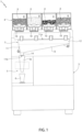
- number 1 indicates as a whole an automatic vending machine for preparing and supplying beverages, e.g. espresso or other coffee-based beverages, tea, chocolate or other cocoa-based beverages, or the like, starting from a ground brewing substance 2, e.g. coffee, tea, cocoa or the like.
- beverages e.g. espresso or other coffee-based beverages, tea, chocolate or other cocoa-based beverages, or the like
- a ground brewing substance 2 e.g. coffee, tea, cocoa or the like.
- the brewing substance 2 is initially provided in grains or beans, in the case of coffee, broad beans, in the case of cocoa, or leaves, in the case of tea.
- the brewing substance 2 could be initially delivered in pellets or other types of artificially obtained grains.
- an automatic vending machine 1 configured to prepare beverages using ground coffee starting from coffee beans or grains as brewing substance 2.
- the vending machine 1 comprises:
- the grinding unit 4 comprises a plurality of grinding chambers 8 housing as many grinding members 10, for example rotating blades configured to grind the brewing substance 2 contained within the respective chamber 8.
- each grinding chamber 8 defines, together with the relative grinding member 10, a grinder of the grinding unit 4.
- the grinding unit 4 is configured to accommodate the same or different qualities or varieties of coffee or grains or beans of different grain sizes in the chambers 8.
- each chamber 8 is configured to accommodate a different type of brewing substance 2, advantageously but not limited to those listed above.
- the grinding unit 4 comprises a single chamber 8 configured to contain and grind, by means of the respective grinding member 10, a single type of brewing substance 2 at a time, for example coffee initially in grains or beans.
- the chambers 8 have respective ground coffee outlets arranged downstream of the grinding members 10, all of which are connected to an inlet 5a of the brewing unit 5 through the brewing device 7.
- the grinding unit 4 and the brewing unit 5 are fixed to, and therefore supported by, the frame 3.
- the supply device 7 is also fixed to the frame 3, in a manner that will be described below.
- the supply device 7 receives an amount, preferably dosed, of brewing substance 2 which is ground at a time by the grinding unit 4 and feeds it to the brewing unit 5 so as to obtain, in a manner that is known and not described in detail, a portion of beverage from an optimal amount (the dosed amount) of brewing substance 2.
- the supply device 7 is configured to be arranged inside the vending machine 1, in particular it is mounted to the frame 3 of the latter, to feed the ground coffee from the grinding unit 4 to the brewing unit 5.
- the supply device 7 comprises a chute 11 configured to receive the aforesaid amount, preferably dosed, of ground coffee from the grinding unit 4 through an inlet opening 11a and convey it to the brewing unit 5 through an outlet opening 11b.
- the chute 11 comprises an upper portion 12 having a constant cross-section, in the present case substantially rectangular with bevelled corners and defining a hopper configured to receive/collect the ground coffee through the opening 11a, and a lower portion 13 having a variable cross-section defining a sort of funnel, in the present case elongated truncated cone, which receives the ground coffee from the hopper and channels it to the brewing unit 5 through a discharge conduit 14, arranged downstream of the lower portion 13 and ending with the opening 11b.
- the chute 11 could be defined by an inclined feeding conduit.
- the chute could not comprise the hopper or the funnel, and may simply be defined by an inclined plane, such as an inclined plate.
- the supply device 7 further comprises a vibration generator 15 associated, in particular functionally coupled, to the chute 11 for applying vibrations to the latter.
- the vibration generator 15 is actuated to apply (i.e. to transmit) the vibrations generated to the chute 11 itself and thus promote the descent of the ground coffee towards the brewing unit 5.
- the vibration generator 15 comprises an electric actuator (or motor) 15a on the output shaft of which an eccentric mass 15b is keyed, the rotation of which generates the vibrations.
- an electric actuator or motor
- the vibration generator 15a can also be used.
- other types of vibration generators such as electromagnetic or piezoelectric actuators, can also be used.
- the supply device 7 comprises at least one connection member 16, in particular two connection members 16, for coupling (as will be seen below, with interposition of parts) the chute 11 to the frame 3 and comprising, each, at least one damper element 17 of the vibrations produced by the generator 15 operatively interposed between the frame 3 and the chute 11.
- the damper elements 17 are made of elastomeric material, for example rubber.
- the supply device 7 comprises a bracket 18 configured to be fixed, to the frame 3 by means of the connection members 16 with the interposition of the damper elements 17.
- damper elements 17 are interposed between the bracket 18 and the frame 3.
- connection members 16 are defined by components that are distinct from the chute 11.
- the chute 11 is integrally fitted to the bracket 18 to be coupled, through the latter, to the frame 3 and to be supported by the latter indirectly through the bracket 18.
- the chute 11 is mounted to the bracket 18 by at least one further connection member 19, in particular by two further connection members 19.
- the chute 11 is coupled to the frame 3 by means of the interposition of the bracket 18, and, as specified below, in a non-contact condition with the frame 3 itself.
- the vibration generator 15 is fixed to the bracket 18 to apply the vibrations to the latter and, suitably, the further connection members 19 are configured to transmit the vibrations from the bracket 18 to the chute 11.
- the chute 11 is mounted on the bracket 18 by means of the further connection members 19, configured to transmit the vibrations from the bracket 18 to the chute 11, and the bracket 18 is in turn fixed to the frame 3 by means of the connection members 16 and with the interposition of the damper elements 17, so that these vibrations are not transmitted, at least in part and preferably in their entirety, to the frame 3.
- each connection member 16 comprises a threaded member, for example a screw 20, for coupling the bracket 18 to the frame 3, and therefore, indirectly, the chute 11 to the frame 3, and an anti-vibration rubber pad mounted to the screw 20 and defining the aforesaid damper element 17.
- each anti-vibration rubber pad has a through hole configured to be engaged by the respective screw 20 in mounting conditions. That is, each rubber pad is "keyed" on the relative screw 20.
- bracket 18 is fixed to the frame 3 by means of the screws 20 and the anti-vibration rubber pads, keyed on the screws 20, are interposed between the frame 3 and the bracket 18.
- the transmission of the vibrations produced by the generator 15 to the frame 3 and therefore to the other components of the vending machine 1, such as for example the grinding unit 4 and the brewing unit 5, is at least limited, in particular substantially prevented, more in particular prevented.
- the Applicant has in fact had the opportunity to observe how these components are particularly sensitive during their operation to stress of various type: the vibrations could in fact cause an undesired movement of the container 6 within the brewing unit 5, or the undesired fall of beans or grains from the grinding unit 4 downwards. Therefore, the damping of the vibrations, which are advantageous for the chute 11 and for letting the brewing substance 2 passing through it completely fall but which are harmful to the other components, increases the overall service life of the vending machine 1 and improves the quality of the beverages produced by it.
- the chute 11 is integrally fitted to the bracket 18 in conditions of mechanical non-interference with the frame 3.
- each further connection member 19 is arranged, in mounting conditions, in a position spaced from the frame 3, so as not to transmit vibrations to the latter.
- each further connection member 19 comprises:
- each seat 21 has an opening for receiving the relative bushing 19a and has a through hole 22 obtained in a bottom wall of the seat 21 itself opposite the opening for receiving the bushing 19a. Accordingly, the respective screw 19b is configured to engage the bushing 19a inserted in said seat 21 through the through hole 22.
- each bushing 19a has a cylindrical shape and, suitably, each seat 21 has a cylindrical shape to accommodate the respective bushing 19a.
- connection members 19 As an alternative to the further connection members 19, other types of connectors may be used provided that they are suitable for connecting the bracket 18 and the chute 11 without interfering with the plate 3a so that the vibrations are not transmitted to the latter.
- the frame 3 comprises a partition septum or partition plate 3a, suitably mounted inside the vending machine 1, which separates a "clean" area of the vending machine 1, at which the brewing substance 2 and any food substance that may be used in the preparation of the beverage (for example, water, milk or artificial flavourings) pass, from a "dirty" area of the vending machine 1, at which no brewing substance 2 or any food substance passes.
- a partition septum or partition plate 3a suitably mounted inside the vending machine 1, which separates a "clean" area of the vending machine 1, at which the brewing substance 2 and any food substance that may be used in the preparation of the beverage (for example, water, milk or artificial flavourings) pass, from a "dirty" area of the vending machine 1, at which no brewing substance 2 or any food substance passes.
- bracket 18 and the chute 11 are arranged on opposite sides of the plate 3a itself.
- the chute 11 is arranged at the "clean" side of the plate 3a and the bracket 18, and therefore the generator 15, are arranged on the opposite side of the plate 3a, i.e. at the "dirty" side of the plate 3a.
- This configuration leads to an improvement in the hygienic operating conditions of the vending machine 1.
- each bushing 19a crosses the plate 3a with clearance and without interference. More particularly, the plate 3a comprises two through holes 23 configured to be engaged, in mounting conditions, by the bushings 19a with radial clearance, so that the chute 11 is directly coupled to the bracket 18 and indirectly, through this, to the frame 3.
- each bushing 19a has a diameter smaller than the diameter of the through holes 23, as shown in Figure 4 .
- each bushing 19a is configured to engage the corresponding through hole 23 with a clearance such that the bushing 19a does not interfere with the plate 3a during operation of the vibration generator 15.
- this configuration results in a better vibrational decoupling of the chute 11 with respect to the frame 3, as it eliminates any possible point of contact, and therefore transmission of vibrations, between the chute 11 and the frame 3.
- the vending machine 1 comprises a control unit (not shown) configured to control:
- the transmission of the vibrations produced by the generator 15 to the frame 3 and therefore to the other components of the vending machine 1, such as for example the grinding unit 4 and the brewing unit 5, is at least limited, in particular substantially prevented, more in particular prevented. This results, as specified above, in an increase in the service life of these components and in an improvement in the quality of the beverage produced.
- the chute 11 is arranged on the opposite side of the plate 3a with respect to the bracket 18 and the generator, the hygienic conditions of the vending machine 1 have improved.
- the chute 11 could be directly coupled to the frame through the connection members 16 and with the interposition of the damper elements 17.
- the supply device 7 does not comprise any bracket 18 and the generator 15 is fixed directly to the chute 11.
- the chute 11 and the bracket 18 could both be arranged on the same side of the plate 3a.
- the generator 15 could be fixed to the bracket and arranged on the opposite side of the plate 3a, or it could be directly fixed to the chute 11 and arranged on the same side as the plate 3a.
Landscapes
- Engineering & Computer Science (AREA)
- Food Science & Technology (AREA)
- Physics & Mathematics (AREA)
- General Physics & Mathematics (AREA)
- Mechanical Engineering (AREA)
- Control Of Vending Devices And Auxiliary Devices For Vending Devices (AREA)
Claims (6)
- Vorrichtung (7) zum Zuführen einer gemahlenen Brühsubstanz (2) zur Zubereitung von Getränken, wobei die Vorrichtung (7) konfiguriert ist, in einer automatischen Getränkeverkaufsmaschine bzw. einem Getränkeverkaufsautomaten (1) angeordnet zu sein, um die gemahlene Brühsubstanz (2) von einer Mahleinheit (4) des Verkaufsautomaten zu einer Brüheinheit (5) des Verkaufsautomaten zu leiten, und umfassend:- eine Rutsche (11), die konfiguriert ist, eine Menge gemahlener Brühsubstanz (2) von der Mahleinheit (4) aufzunehmen und zu der Brüheinheit (5) zu befördern;- einen Vibrationsgenerator (15), der mit der Rutsche (11) verbunden ist, um Vibrationen auf diese auszuüben bzw. sie in Vibrationen zu versetzen;dadurch gekennzeichnet, dass die Vorrichtung (7) umfasst:- zumindest ein Verbindungsglied (16) zum Koppeln der Rutsche (11) mit einem festen Rahmen (3) des Getränkeverkaufsautomaten (1) und umfassend zumindest ein Dämpferelement (17) zum Dämpfen von auf den Rahmen (3) übertragenen Vibrationen; und- eine Halterung (18), die konfiguriert ist, mittels des Verbindungsglieds (16) unter Zwischenanordnung des Dämpferelements (17) an dem Rahmen (3) befestigt zu sein;wobei die Rutsche (11) integral bzw. einstückig an der Halterung (18) angebracht ist, um durch die Halterung (18) mit dem Rahmen (3) gekoppelt und durch den Rahmen (3) gestützt bzw. getragen zu sein,wobei der Vibrationsgenerator (15) an der Halterung (18) befestigt ist, um Vibrationen auf die Halterung (18) auszuüben;wobei das zumindest eine Dämpferelement (17) konfiguriert ist, operativ zwischen dem Rahmen (3) und der Halterung (18) angeordnet zu sein, wenn die Zuführvorrichtung (7) an dem Rahmen (3) montiert ist,wobei die Rutsche (11) mittels zumindest eines weiteren Verbindungsglieds (19), das konfiguriert ist, die Schwingungen von der Halterung (18) auf die Rutsche (11) zu übertragen, integral bzw. einstückig an der Halterung (18) angebracht ist,wobei das weitere Verbindungsglied (19) umfasst:- eine Gewindebuchse (19a), die an einer von Rutsche (11) und Halterung (18) befestigt ist und konfiguriert ist, in einen jeweiligen Sitz (21) einzugreifen, der in der anderen von Rutsche (11) und Halterung (18) vorhanden ist; und- ein Gewindeglied (19b), konfiguriert ist, in die Buchse (19a) einzugreifen, die in den Sitz (21) eingesetzt ist, um die Rutsche (11) lösbar an der Halterung (18) zu befestigen;wobei die Buchse (19a) konfiguriert ist, ein Durchgangsloch (23) zu durchqueren, das in einer Trennplatte (3a) des Rahmens (3) mit einem Abstand derart ausgebildet ist, dass die Buchse (19a) während des Betriebs des Vibrationsgenerators (15) nicht mit der Trennplatte (3a) zusammentrifft; und wobei die Halterung (18) und die Rutsche (11) konfiguriert sind, auf gegenüberliegenden bzw. entgegengesetzten Seiten der Trennplatte (3a) angeordnet zu sein.
- Zuführvorrichtung nach Anspruch 1, wobei das weitere Verbindungsglied (19) konfiguriert ist, in einer von dem Rahmen (3) beabstandeten Position angeordnet zu sein, wenn die Zuführvorrichtung (7) an dem Rahmen (3) montiert ist.
- Vorrichtung nach Anspruch 1 oder 2, wobei die Buchse (19a) an der Halterung (18) befestigt ist und wobei der Sitz (21) in der Rutsche (11) vorhanden ist.
- Zuführvorrichtung nach einem der vorhergehenden Ansprüche, wobei das zumindest eine Dämpferelement (17) aus Elastomermaterial besteht.
- Zuführvorrichtung nach Anspruch 4, wobei das Verbindungsglied (16) ein Gewindeglied (20) zum Koppeln der Rutsche (11) mit dem Rahmen (3) und zumindest ein Antivibrationsgummipolster umfasst, das an bzw. auf dem Gewindeglied (20) montiert ist und das Dämpferelement (17) definiert.
- Verkaufsautomat bzw. automatische Verkaufsmaschine (1) zum Zubereiten von Getränken ausgehend von einer Brühsubstanz (2), wobei der Verkaufsautomat (1) umfasst:- eine Mahleinheit (4), die konfiguriert ist, die zu mahlende Brühsubstanz (2) aufzunehmen, und konfiguriert ist, die Brühsubstanz (2) zu mahlen, um ein gemahlenes Produkt zu erhalten;- eine Brüheinheit (5), die konfiguriert ist, das gemahlene Produkt aufzunehmen und es zur Zubereitung eines Getränks aufzubrühen;- einen festen Rahmen (3), an dem die Mahleinheit (4) und die Brüheinheit (5) montiert sind; und- eine Zufuhrvorrichtung (7) nach einem der vorhergehenden Ansprüche;wobei die Rutsche (11) mittels des Verbindungsglieds (16) und unter Zwischenanordnung des Dämpferelements (17) mit dem Rahmen (3) gekoppelt ist.
Applications Claiming Priority (3)
| Application Number | Priority Date | Filing Date | Title |
|---|---|---|---|
| EP21173969 | 2021-05-14 | ||
| IT102021000015044A IT202100015044A1 (it) | 2021-06-09 | 2021-06-09 | Dispositivo di erogazione di una sostanza da infusione macinata per la preparazione di bevande |
| PCT/IB2022/054331 WO2022238893A1 (en) | 2021-05-14 | 2022-05-10 | Device for supplying a ground brewing substance for preparing beverages |
Publications (2)
| Publication Number | Publication Date |
|---|---|
| EP4338140A1 EP4338140A1 (de) | 2024-03-20 |
| EP4338140B1 true EP4338140B1 (de) | 2024-09-04 |
Family
ID=81748543
Family Applications (1)
| Application Number | Title | Priority Date | Filing Date |
|---|---|---|---|
| EP22724266.6A Active EP4338140B1 (de) | 2021-05-14 | 2022-05-10 | Vorrichtung zur bereitstellung einer gemahlenen brühsubstanz zur zubereitung von getränken |
Country Status (3)
| Country | Link |
|---|---|
| EP (1) | EP4338140B1 (de) |
| TW (1) | TW202317015A (de) |
| WO (1) | WO2022238893A1 (de) |
Citations (2)
| Publication number | Priority date | Publication date | Assignee | Title |
|---|---|---|---|---|
| US6745668B2 (en) * | 2000-01-24 | 2004-06-08 | Unic S.A.S. | Unit for making beverages by brewing and machine incorporating same |
| WO2018044845A1 (en) * | 2016-08-29 | 2018-03-08 | Auroma Brewing Company | System and method for automated coffee grind refinement |
Family Cites Families (11)
| Publication number | Priority date | Publication date | Assignee | Title |
|---|---|---|---|---|
| US2182131A (en) * | 1933-08-28 | 1939-12-05 | Leland S Maede | Coffee mill |
| DE3013987C2 (de) * | 1980-04-11 | 1983-11-17 | Friedrich Wilhelm 4030 Ratingen Nette | Schwingmühle |
| US4378078A (en) * | 1981-06-26 | 1983-03-29 | Daniels Paul J | Granulated material dispenser |
| DE3834339A1 (de) * | 1988-10-08 | 1990-04-12 | Ulrich Reissmann | Vorrichtung zum entladen von behaeltern |
| JPH05290266A (ja) * | 1992-04-14 | 1993-11-05 | Fuji Electric Co Ltd | カップ式自動販売機の原料供給装置 |
| US6227102B1 (en) * | 1999-04-27 | 2001-05-08 | John C. K. Sham | Automatic coffee maker with grinder |
| US6713126B2 (en) * | 2002-05-24 | 2004-03-30 | Mars, Incorporated | Particulate metering and alignment apparatus |
| JP6244076B2 (ja) * | 2011-10-21 | 2017-12-06 | 株式会社タカゾノテクノロジー | 薬剤供給装置 |
| CN109956094A (zh) * | 2017-12-22 | 2019-07-02 | 天津兴扬瑞迪科技有限公司 | 高效智能包装机 |
| US10995042B2 (en) * | 2018-11-13 | 2021-05-04 | Whirlpool Corporation | Food waste recycling appliance |
| CN111439425A (zh) * | 2020-04-09 | 2020-07-24 | 苏州如德科技有限公司 | 一种适用于颗粒状中药的高精度发药装置 |
-
2022
- 2022-05-10 EP EP22724266.6A patent/EP4338140B1/de active Active
- 2022-05-10 WO PCT/IB2022/054331 patent/WO2022238893A1/en not_active Ceased
- 2022-05-13 TW TW111118117A patent/TW202317015A/zh unknown
Patent Citations (2)
| Publication number | Priority date | Publication date | Assignee | Title |
|---|---|---|---|---|
| US6745668B2 (en) * | 2000-01-24 | 2004-06-08 | Unic S.A.S. | Unit for making beverages by brewing and machine incorporating same |
| WO2018044845A1 (en) * | 2016-08-29 | 2018-03-08 | Auroma Brewing Company | System and method for automated coffee grind refinement |
Also Published As
| Publication number | Publication date |
|---|---|
| EP4338140A1 (de) | 2024-03-20 |
| TW202317015A (zh) | 2023-05-01 |
| WO2022238893A1 (en) | 2022-11-17 |
Similar Documents
| Publication | Publication Date | Title |
|---|---|---|
| JP7554818B2 (ja) | グラインダおよびこのようなグラインダを備えたコーヒーメーカー | |
| CN104363801B (zh) | 咖啡机 | |
| US12161248B2 (en) | Device for feeding coffee powder into a brewing chamber of a coffee machine | |
| CA1206768A (en) | Process and an apparatus for the proportioning of coffee powder in a coffee machine | |
| KR101999095B1 (ko) | 슈트를 이용한 완전 현미 선별기 | |
| EP2424414B1 (de) | Getränkezubereitungsverfahren | |
| US20210353094A1 (en) | Coffee bean feeder, selecting unit comprising such feeder and coffee machine comprising such selecting unit | |
| EP4338140B1 (de) | Vorrichtung zur bereitstellung einer gemahlenen brühsubstanz zur zubereitung von getränken | |
| US20180125300A1 (en) | Apparatus and method for grinding coffee beans | |
| CN113163976A (zh) | 咖啡机和用于操作这种咖啡机的方法 | |
| AU729569B2 (en) | Device for the preparation of coffee powder | |
| US2852202A (en) | Coffee grinder | |
| IT202100015044A1 (it) | Dispositivo di erogazione di una sostanza da infusione macinata per la preparazione di bevande | |
| KR102914277B1 (ko) | 그라인딩 장치 및 그 조정 방법 | |
| EP3692868A1 (de) | Automatische kaffeemaschine | |
| US20250176763A1 (en) | Apparatus and method for grinding seeds | |
| KR102129211B1 (ko) | 커피 미분 제거기 | |
| RU2840608C1 (ru) | Способ выдачи молотого кофе | |
| CN222840832U (zh) | 研磨模块及饮品制备设备 | |
| CN121712430A (zh) | 用于对咖啡豆进行研磨的设备 | |
| CN224055805U (zh) | 咖啡机 | |
| CN220277181U (zh) | 一种固体饮料加工用研磨装置 | |
| US20220257056A1 (en) | Grinder/doser device for coffee beans | |
| CN210184414U (zh) | 一种用于巧克力生产的可可豆精磨机 | |
| EP3697272B1 (de) | Automatische getränkezubereitungsmachine |
Legal Events
| Date | Code | Title | Description |
|---|---|---|---|
| STAA | Information on the status of an ep patent application or granted ep patent |
Free format text: STATUS: UNKNOWN |
|
| STAA | Information on the status of an ep patent application or granted ep patent |
Free format text: STATUS: THE INTERNATIONAL PUBLICATION HAS BEEN MADE |
|
| STAA | Information on the status of an ep patent application or granted ep patent |
Free format text: STATUS: EXAMINATION IS IN PROGRESS |
|
| PUAI | Public reference made under article 153(3) epc to a published international application that has entered the european phase |
Free format text: ORIGINAL CODE: 0009012 |
|
| 17P | Request for examination filed |
Effective date: 20231127 |
|
| AK | Designated contracting states |
Kind code of ref document: A1 Designated state(s): AL AT BE BG CH CY CZ DE DK EE ES FI FR GB GR HR HU IE IS IT LI LT LU LV MC MK MT NL NO PL PT RO RS SE SI SK SM TR |
|
| GRAP | Despatch of communication of intention to grant a patent |
Free format text: ORIGINAL CODE: EPIDOSNIGR1 |
|
| STAA | Information on the status of an ep patent application or granted ep patent |
Free format text: STATUS: GRANT OF PATENT IS INTENDED |
|
| DAV | Request for validation of the european patent (deleted) | ||
| DAX | Request for extension of the european patent (deleted) | ||
| INTG | Intention to grant announced |
Effective date: 20240328 |
|
| P01 | Opt-out of the competence of the unified patent court (upc) registered |
Effective date: 20240529 |
|
| GRAS | Grant fee paid |
Free format text: ORIGINAL CODE: EPIDOSNIGR3 |
|
| GRAA | (expected) grant |
Free format text: ORIGINAL CODE: 0009210 |
|
| STAA | Information on the status of an ep patent application or granted ep patent |
Free format text: STATUS: THE PATENT HAS BEEN GRANTED |
|
| AK | Designated contracting states |
Kind code of ref document: B1 Designated state(s): AL AT BE BG CH CY CZ DE DK EE ES FI FR GB GR HR HU IE IS IT LI LT LU LV MC MK MT NL NO PL PT RO RS SE SI SK SM TR |
|
| REG | Reference to a national code |
Ref country code: GB Ref legal event code: FG4D |
|
| REG | Reference to a national code |
Ref country code: CH Ref legal event code: EP |
|
| REG | Reference to a national code |
Ref country code: IE Ref legal event code: FG4D |
|
| REG | Reference to a national code |
Ref country code: DE Ref legal event code: R096 Ref document number: 602022005904 Country of ref document: DE |
|
| REG | Reference to a national code |
Ref country code: LT Ref legal event code: MG9D |
|
| REG | Reference to a national code |
Ref country code: NL Ref legal event code: MP Effective date: 20240904 |
|
| PG25 | Lapsed in a contracting state [announced via postgrant information from national office to epo] |
Ref country code: NO Free format text: LAPSE BECAUSE OF FAILURE TO SUBMIT A TRANSLATION OF THE DESCRIPTION OR TO PAY THE FEE WITHIN THE PRESCRIBED TIME-LIMIT Effective date: 20241204 |
|
| PG25 | Lapsed in a contracting state [announced via postgrant information from national office to epo] |
Ref country code: GR Free format text: LAPSE BECAUSE OF FAILURE TO SUBMIT A TRANSLATION OF THE DESCRIPTION OR TO PAY THE FEE WITHIN THE PRESCRIBED TIME-LIMIT Effective date: 20241205 Ref country code: FI Free format text: LAPSE BECAUSE OF FAILURE TO SUBMIT A TRANSLATION OF THE DESCRIPTION OR TO PAY THE FEE WITHIN THE PRESCRIBED TIME-LIMIT Effective date: 20240904 |
|
| PG25 | Lapsed in a contracting state [announced via postgrant information from national office to epo] |
Ref country code: BG Free format text: LAPSE BECAUSE OF FAILURE TO SUBMIT A TRANSLATION OF THE DESCRIPTION OR TO PAY THE FEE WITHIN THE PRESCRIBED TIME-LIMIT Effective date: 20240904 |
|
| PG25 | Lapsed in a contracting state [announced via postgrant information from national office to epo] |
Ref country code: LV Free format text: LAPSE BECAUSE OF FAILURE TO SUBMIT A TRANSLATION OF THE DESCRIPTION OR TO PAY THE FEE WITHIN THE PRESCRIBED TIME-LIMIT Effective date: 20240904 |
|
| PG25 | Lapsed in a contracting state [announced via postgrant information from national office to epo] |
Ref country code: HR Free format text: LAPSE BECAUSE OF FAILURE TO SUBMIT A TRANSLATION OF THE DESCRIPTION OR TO PAY THE FEE WITHIN THE PRESCRIBED TIME-LIMIT Effective date: 20240904 |
|
| PG25 | Lapsed in a contracting state [announced via postgrant information from national office to epo] |
Ref country code: RS Free format text: LAPSE BECAUSE OF FAILURE TO SUBMIT A TRANSLATION OF THE DESCRIPTION OR TO PAY THE FEE WITHIN THE PRESCRIBED TIME-LIMIT Effective date: 20241204 Ref country code: ES Free format text: LAPSE BECAUSE OF FAILURE TO SUBMIT A TRANSLATION OF THE DESCRIPTION OR TO PAY THE FEE WITHIN THE PRESCRIBED TIME-LIMIT Effective date: 20240904 |
|
| PG25 | Lapsed in a contracting state [announced via postgrant information from national office to epo] |
Ref country code: RS Free format text: LAPSE BECAUSE OF FAILURE TO SUBMIT A TRANSLATION OF THE DESCRIPTION OR TO PAY THE FEE WITHIN THE PRESCRIBED TIME-LIMIT Effective date: 20241204 Ref country code: NO Free format text: LAPSE BECAUSE OF FAILURE TO SUBMIT A TRANSLATION OF THE DESCRIPTION OR TO PAY THE FEE WITHIN THE PRESCRIBED TIME-LIMIT Effective date: 20241204 Ref country code: LV Free format text: LAPSE BECAUSE OF FAILURE TO SUBMIT A TRANSLATION OF THE DESCRIPTION OR TO PAY THE FEE WITHIN THE PRESCRIBED TIME-LIMIT Effective date: 20240904 Ref country code: HR Free format text: LAPSE BECAUSE OF FAILURE TO SUBMIT A TRANSLATION OF THE DESCRIPTION OR TO PAY THE FEE WITHIN THE PRESCRIBED TIME-LIMIT Effective date: 20240904 Ref country code: GR Free format text: LAPSE BECAUSE OF FAILURE TO SUBMIT A TRANSLATION OF THE DESCRIPTION OR TO PAY THE FEE WITHIN THE PRESCRIBED TIME-LIMIT Effective date: 20241205 Ref country code: FI Free format text: LAPSE BECAUSE OF FAILURE TO SUBMIT A TRANSLATION OF THE DESCRIPTION OR TO PAY THE FEE WITHIN THE PRESCRIBED TIME-LIMIT Effective date: 20240904 Ref country code: ES Free format text: LAPSE BECAUSE OF FAILURE TO SUBMIT A TRANSLATION OF THE DESCRIPTION OR TO PAY THE FEE WITHIN THE PRESCRIBED TIME-LIMIT Effective date: 20240904 Ref country code: BG Free format text: LAPSE BECAUSE OF FAILURE TO SUBMIT A TRANSLATION OF THE DESCRIPTION OR TO PAY THE FEE WITHIN THE PRESCRIBED TIME-LIMIT Effective date: 20240904 |
|
| REG | Reference to a national code |
Ref country code: AT Ref legal event code: MK05 Ref document number: 1721239 Country of ref document: AT Kind code of ref document: T Effective date: 20240904 |
|
| PG25 | Lapsed in a contracting state [announced via postgrant information from national office to epo] |
Ref country code: NL Free format text: LAPSE BECAUSE OF FAILURE TO SUBMIT A TRANSLATION OF THE DESCRIPTION OR TO PAY THE FEE WITHIN THE PRESCRIBED TIME-LIMIT Effective date: 20240904 |
|
| PG25 | Lapsed in a contracting state [announced via postgrant information from national office to epo] |
Ref country code: PT Free format text: LAPSE BECAUSE OF FAILURE TO SUBMIT A TRANSLATION OF THE DESCRIPTION OR TO PAY THE FEE WITHIN THE PRESCRIBED TIME-LIMIT Effective date: 20250106 Ref country code: IS Free format text: LAPSE BECAUSE OF FAILURE TO SUBMIT A TRANSLATION OF THE DESCRIPTION OR TO PAY THE FEE WITHIN THE PRESCRIBED TIME-LIMIT Effective date: 20250104 |
|
| PG25 | Lapsed in a contracting state [announced via postgrant information from national office to epo] |
Ref country code: RO Free format text: LAPSE BECAUSE OF FAILURE TO SUBMIT A TRANSLATION OF THE DESCRIPTION OR TO PAY THE FEE WITHIN THE PRESCRIBED TIME-LIMIT Effective date: 20240904 Ref country code: SM Free format text: LAPSE BECAUSE OF FAILURE TO SUBMIT A TRANSLATION OF THE DESCRIPTION OR TO PAY THE FEE WITHIN THE PRESCRIBED TIME-LIMIT Effective date: 20240904 |
|
| PG25 | Lapsed in a contracting state [announced via postgrant information from national office to epo] |
Ref country code: EE Free format text: LAPSE BECAUSE OF FAILURE TO SUBMIT A TRANSLATION OF THE DESCRIPTION OR TO PAY THE FEE WITHIN THE PRESCRIBED TIME-LIMIT Effective date: 20240904 Ref country code: AT Free format text: LAPSE BECAUSE OF FAILURE TO SUBMIT A TRANSLATION OF THE DESCRIPTION OR TO PAY THE FEE WITHIN THE PRESCRIBED TIME-LIMIT Effective date: 20240904 |
|
| PG25 | Lapsed in a contracting state [announced via postgrant information from national office to epo] |
Ref country code: CZ Free format text: LAPSE BECAUSE OF FAILURE TO SUBMIT A TRANSLATION OF THE DESCRIPTION OR TO PAY THE FEE WITHIN THE PRESCRIBED TIME-LIMIT Effective date: 20240904 Ref country code: PL Free format text: LAPSE BECAUSE OF FAILURE TO SUBMIT A TRANSLATION OF THE DESCRIPTION OR TO PAY THE FEE WITHIN THE PRESCRIBED TIME-LIMIT Effective date: 20240904 |
|
| PG25 | Lapsed in a contracting state [announced via postgrant information from national office to epo] |
Ref country code: SK Free format text: LAPSE BECAUSE OF FAILURE TO SUBMIT A TRANSLATION OF THE DESCRIPTION OR TO PAY THE FEE WITHIN THE PRESCRIBED TIME-LIMIT Effective date: 20240904 |
|
| REG | Reference to a national code |
Ref country code: DE Ref legal event code: R097 Ref document number: 602022005904 Country of ref document: DE |
|
| PGFP | Annual fee paid to national office [announced via postgrant information from national office to epo] |
Ref country code: DE Payment date: 20250528 Year of fee payment: 4 |
|
| PG25 | Lapsed in a contracting state [announced via postgrant information from national office to epo] |
Ref country code: DK Free format text: LAPSE BECAUSE OF FAILURE TO SUBMIT A TRANSLATION OF THE DESCRIPTION OR TO PAY THE FEE WITHIN THE PRESCRIBED TIME-LIMIT Effective date: 20240904 |
|
| PLBE | No opposition filed within time limit |
Free format text: ORIGINAL CODE: 0009261 |
|
| STAA | Information on the status of an ep patent application or granted ep patent |
Free format text: STATUS: NO OPPOSITION FILED WITHIN TIME LIMIT |
|
| PGFP | Annual fee paid to national office [announced via postgrant information from national office to epo] |
Ref country code: IT Payment date: 20250531 Year of fee payment: 4 |
|
| PGFP | Annual fee paid to national office [announced via postgrant information from national office to epo] |
Ref country code: CH Payment date: 20250601 Year of fee payment: 4 |
|
| 26N | No opposition filed |
Effective date: 20250605 |
|
| PG25 | Lapsed in a contracting state [announced via postgrant information from national office to epo] |
Ref country code: SE Free format text: LAPSE BECAUSE OF FAILURE TO SUBMIT A TRANSLATION OF THE DESCRIPTION OR TO PAY THE FEE WITHIN THE PRESCRIBED TIME-LIMIT Effective date: 20240904 |
|
| PG25 | Lapsed in a contracting state [announced via postgrant information from national office to epo] |
Ref country code: LU Free format text: LAPSE BECAUSE OF NON-PAYMENT OF DUE FEES Effective date: 20250510 |
|
| REG | Reference to a national code |
Ref country code: BE Ref legal event code: MM Effective date: 20250531 |
|
| PG25 | Lapsed in a contracting state [announced via postgrant information from national office to epo] |
Ref country code: MC Free format text: LAPSE BECAUSE OF FAILURE TO SUBMIT A TRANSLATION OF THE DESCRIPTION OR TO PAY THE FEE WITHIN THE PRESCRIBED TIME-LIMIT Effective date: 20240904 |
|
| PG25 | Lapsed in a contracting state [announced via postgrant information from national office to epo] |
Ref country code: IE Free format text: LAPSE BECAUSE OF NON-PAYMENT OF DUE FEES Effective date: 20250510 |
|
| PG25 | Lapsed in a contracting state [announced via postgrant information from national office to epo] |
Ref country code: BE Free format text: LAPSE BECAUSE OF NON-PAYMENT OF DUE FEES Effective date: 20250531 |
|
| PG25 | Lapsed in a contracting state [announced via postgrant information from national office to epo] |
Ref country code: FR Free format text: LAPSE BECAUSE OF NON-PAYMENT OF DUE FEES Effective date: 20250531 |