EP4338893B1 - Handwerkzeug mit pufferungseffekt - Google Patents
Handwerkzeug mit pufferungseffekt Download PDFInfo
- Publication number
- EP4338893B1 EP4338893B1 EP23196842.1A EP23196842A EP4338893B1 EP 4338893 B1 EP4338893 B1 EP 4338893B1 EP 23196842 A EP23196842 A EP 23196842A EP 4338893 B1 EP4338893 B1 EP 4338893B1
- Authority
- EP
- European Patent Office
- Prior art keywords
- hand tool
- segment
- shock
- absorbing
- buffering effect
- Prior art date
- Legal status (The legal status is an assumption and is not a legal conclusion. Google has not performed a legal analysis and makes no representation as to the accuracy of the status listed.)
- Active
Links
Images





Classifications
-
- B—PERFORMING OPERATIONS; TRANSPORTING
- B25—HAND TOOLS; PORTABLE POWER-DRIVEN TOOLS; MANIPULATORS
- B25G—HANDLES FOR HAND IMPLEMENTS
- B25G1/00—Handle constructions
- B25G1/10—Handle constructions characterised by material or shape
-
- B—PERFORMING OPERATIONS; TRANSPORTING
- B25—HAND TOOLS; PORTABLE POWER-DRIVEN TOOLS; MANIPULATORS
- B25G—HANDLES FOR HAND IMPLEMENTS
- B25G1/00—Handle constructions
- B25G1/01—Shock-absorbing means
-
- B—PERFORMING OPERATIONS; TRANSPORTING
- B25—HAND TOOLS; PORTABLE POWER-DRIVEN TOOLS; MANIPULATORS
- B25D—PERCUSSIVE TOOLS
- B25D1/00—Hand hammers; Hammer heads of special shape or materials
- B25D1/12—Hand hammers; Hammer heads of special shape or materials having shock-absorbing means
Definitions
- the present invention relates to a hand tool, and more particularly to a hand tool with a buffering effect that can be held according to usage needs and can improve a shock absorption effect.
- a conventional hammer or axe is used to tap or chop an object and may have a grip cover mounted on an end of a handle of the conventional hammer or axe.
- the grip cover may reduce a reaction force of the conventional hammer or axe due to collision with the object.
- the grip cover disposed on the end of the handle may provide a shock absorption and buffering effect to the conventional hammer or axe, and a length of the grip cover is mostly less than half of a length of the handle. That is, only when the user holds the end of the handle, the grip cover can provide a shock-absorbing or buffering effect.
- the conventional hammer or axe is used to move at a close distance or in a small range, the user may hold the handle away from the grip cover.
- the outermost rigid layer can include a portion that at least partially surrounds the grip end. In one aspect, that portion of the outermost rigid layer that surrounds the intermediate section is undulated and that portion of the outermost rigid layer that surrounds the grip end is free of undulations.
- the tool handle dampen vibration that is transmitted from the impact end of the tool handle to the grip end that is held by the user.
- the force-limiting and damping device has a body, a tapping element, a shock-absorbing element, and a limiting module.
- the body has a connecting segment and a holding segment.
- the tapping element is connected to the body and has a mounting segment, a tapping segment, and a fixing segment.
- the mounting segment is movably connected to the connecting segment.
- the tapping segment is disposed on the mounting segment.
- the shock-absorbing element is mounted on the mounting segment and abuts the connecting segment and the tapping segment.
- the limiting module is mounted between the body and the tapping element and has a force-limiting element mounted between the mounting segment and the connecting segment to provide a force-limiting reminder and damping effect.
- the vibration reduction mechanism for a hand operated striking tool includes a collar coupled to a portion of a handle of the hand-operated striking tool, at least one sleeve interposed over the collar, and at least one pin interconnecting the collar to the handle, wherein the at least one pin retains a position of the collar near a first end of the handle.
- the hammer includes a handle, a hammer head, and an elastic group.
- the hammer head is set on a long handle with a percussion head, a nail pull part, a hammer head body, and a nail pull support.
- the hammer head body is located between the striking head and the nail pulling part.
- the nail pulling support part is located on the top of the hammer head. Its contour extends to the hammer head body and ridges and then descends towards the striking head.
- the elastic group is provided with damping elastic parts and auxiliary elastic parts, the contour of the nail puller support part of the creation ridges before the hammer head body and then descends toward the striking head, which can solve the lack of existing hammer heads to optimize the nail pull function, which leads to the consumption of nail pulling operations.
- the damping handle is wrapped by an internal damping layer and an external damping layer which are softer than the handle and form the damping handle.
- the hammer or other hand tool has a head to which is attached a handle.
- the handle has a plurality of spring steel rods extending substantially the length of the handle and extending into the head where the rods are affixed by a plate.
- Spacer plates with holes are positioned at spaced locations along the rods.
- the rods and spacer plates are encased in a rubber material that forms the outer surface of the handle.
- the rods and spacer plates at the end of the handle form a reinforced lanyard hole.
- a collar is formed on the handle adjacent the head.
- the head of the hammer has angled deflecting pads adjacent the striking faces.
- the axe or hammer includes axe head or hammer head with assembling blind hole and a handle, wherein the bottom part of the assembling blind hole is inverted tapered shape, and the part of the assembling blind hole, which is away from the bottom part of the assembling blind hole and is above the middle part and below the top part of the assembling blind hole, has a tubular shape.
- the handle In the assembling blind hole there is an inverted wedge whose shape corresponds with the shape of the blind hole, the handle is tubular, whose front part for assembling locates between the blind hole and the inverted taper part of the wedge.
- the front part locates between the blind hole and the inverted taper part of the wedge, in the course of assembling axe head or hammer head and the handle, due to inverted wedge producing great compressing force, the axe' or hammer's resistance to separating is increase with great extent, its reliability is also enhanced, and the life of validity is prolonged over 2 times than the known axe or hammer.
- the present invention tends to provide a hand tool with a buffering effect to mitigate the aforementioned problems.
- a first embodiment of a hand tool with a buffering effect in accordance with the present invention comprises a body 10, a working element 20, and at least one shock-absorbing element 30.
- the body 10 may be an elongated shaft, and has a holding end 11 and a connecting end 12.
- the holding end 11 and the connecting end 12 of the body 10 are respectively disposed on two ends of the body 10.
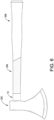
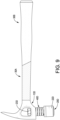
- the working element 20 may be a hammer head and is connected to the connecting end 12 of the body 10.
- the at least one shock-absorbing element 30 is disposed on the body 10 between the holding end 11 and the connecting end 12. When a user holds the body 10 to tap an object by the working element 20, the at least one shock-absorbing element 30 can absorb the vibration of the hand tool to provide a shock absorption effect.
- the at least one shock-absorbing element 30 may be a sleeve made of silicone rubber, rubber or a thermoplastic rubber material.
- the body 10 has a length L1
- the at least one shock-absorbing element 30 has a length L2
- the length L2 of the at least one shock-absorbing element 30 is larger than a half of the length L1 of the body 10 and less than or equal to the length L1 of the body 10 (i.e. 1/2L1 ⁇ L2 ⁇ L1), and this may increase a range for holding the body 10 in use.
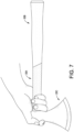
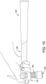
- a user when the body 10 of the hand tool of the present invention needs to be swung over a long distance or in a large amplitude, a user can hold the at least one shock-absorbing element 30 close to the holding end 11, and a reaction force generated when the working element 20 colliding with an object can be reduced to transmit to the user's hand via the at least one shock-absorbing element 30.
- the body 10 of the hand tool of the present invention needs to be swung over a close or small range, the user can hold the at least one shock-absorbing element 30 close to the connecting end 12, and a reaction force generated when the working element 20 colliding with the object also can be reduced to transmit to the user's hand via the at least one shock-absorbing element 30.
- the at least one shock-absorbing element 30 can provide a shock-absorbing and buffering effect to the user.
- the at least one shock-absorbing element 30 may have a single thickness or a thickness that gradually increases from the connecting end 12 toward the holding end 11 of the body 10.
- a second embodiment of a hand tool in accordance with the present invention is substantially the same as the first embodiment except for the following features.
- the hand tool has multiple shock-absorbing elements 30A, 30B, and the multiple shock-absorbing elements 30A, 30B are disposed on the body 10 and abut each other.
- the multiple shock-absorbing elements 30A, 30B can be made of the same or different materials, and each one of the shock-absorbing elements 30A, 30B can have the same or different thicknesses.
- the multiple shock-absorbing elements 30A, 30B have a total length L2, and the total length L2 is larger than a half of the length L1 of the body 10 and less than or equal to the length L1 of the body 10 (i.e. 1/2L1 ⁇ L2 ⁇ L1).
- the user when the hand tool of the present invention needs to be swung over a long distance or in a large amplitude, the user can hold the shock-absorbing element 30B close to the holding end 11 to reduce the reaction force by the shock-absorbing element 30B. Therefore, in use, the user can hold the body 10 with a corresponding one of the multiple shock-absorbing elements 30A, 30B to provide a shock-absorbing and buffering effect.
Landscapes
- Engineering & Computer Science (AREA)
- Mechanical Engineering (AREA)
- Percussive Tools And Related Accessories (AREA)
- Workshop Equipment, Work Benches, Supports, Or Storage Means (AREA)
- Professional, Industrial, Or Sporting Protective Garments (AREA)
- Knives (AREA)
Claims (9)
- Handwerkzeug mit Puffereffekt, wobei das Handwerkzeug umfasst:einen Körper (10, 10D), der ein länglicher Schaft ist und aufweistein Halteende (11), das an einem der beiden Enden des Körpers (10, 10D) angeordnet ist; undein Verbindungsende (12), das an dem anderen der beiden Enden des Körpers (10, 10D) angeordnet ist;ein Arbeitselement (20, 20C, 20D), das mit dem Verbindungsende (11) des Körpers (10, 10D) verbunden ist; und das Handwerkzeug dadurch gekennzeichnet ist, dass es ferner umfasst:
mehrere stoßdämpfende Elemente (30A, 30B), die an dem Körper (10, 10D) zwischen dem Halteende (11) und dem Verbindungsende (12) angeordnet sind, die aneinander anliegen und aus unterschiedlichen Materialien bestehen, und wobei die mehreren stoßdämpfenden Elemente (30A, 30B) eine Gesamtlänge (L2) aufweisen, die größer als die Hälfte einer Länge (L1) des Körpers (10, 10D) und kleiner oder gleich der Länge (L1) des Körpers (10, 10D) ist;wobei eine Stoßdämpfungs- und Puffereffekt durch die mehreren stoßdämpfenden Elemente (30A, 30B) bereitgestellt wird, wenn ein Benutzer den Körper (10, 10D) hält und das Arbeitselement (20, 20C, 20D) verwendet. - Handwerkzeug gemäß Anspruch 1, wobei das Arbeitselement (20, 20D) ein Hammerkopf ist.
- Handwerkzeug gemäß Anspruch 1, wobei das Arbeitselement (20C) eine Axtklinge ist.
- Handwerkzeug gemäß Anspruch 1, wobei der Körper(10D) ein Verbindungssegment (13D, 13E) aufweist, das an dem Verbindungsende (12) angeordnet ist; das Verbindungssegment (13D, 13E) eine Befestigungsöffnung (131D) aufweist; das Arbeitselement (20D) beweglich mit dem Verbindungssegment (13D, 13E) verbunden ist und ein Befestigungssegment (21D) aufweist, das beweglich mit der Befestigungsöffnung (131D) des Verbindungssegments (13D, 13E) verbunden ist; ein Gewindeschnittsegment (22D, 22E), das an einem Ende des Montagesegments (21D) angeordnet und unterhalb des Verbindungssegments (13D, 13E) montiert ist; undein Befestigungssegment (23D), das mit dem Montagesegment (21D) gegenüber dem Gewindeschnittsegment (22D, 22E) verbunden ist und an das Verbindungssegment (13D) anliegt; und das Handwerkzeug ein elastisches Element (40D, 40E) aufweist, das zwischen dem Verbindungssegment (13D, 13E) und dem Gewindeschnittsegment (22D, 22E) angeordnet ist.
- Handwerkzeug gemäß Anspruch 4, wobei das Schlagsegment (22E) des Arbeitselements (20) eine Axtklinge ist.
- Handwerkzeug gemäß einem der Ansprüche 1 bis 5, wobei jedes der mehreren stoßdämpfenden Elemente (30A, 30B) eine Hülse aus Silikonkautschuk, Gummi oder einem thermoplastischen Kautschukmaterial ist.
- Handwerkzeug gemäß einem der Ansprüche 1 bis 5, wobei jedes der mehreren stoßdämpfenden Elemente (30A, 30B) eine gleichmäßige Dicke aufweist.
- Handwerkzeug gemäß einem der Ansprüche 1 bis 5, wobei jedes der mehreren stoßdämpfenden Elemente (30A, 30B) eine Dicke aufweist, die von dem Verbindungsende (12) zu dem Halteende (11) des Körpers (10, 10D) hin allmählich zunimmt.
- Handwerkzeug gemäß einem der Ansprüche 1 bis 5, wobei jedes der mehreren stoßdämpfenden Elemente (30A, 30B) eine unterschiedliche Dicke aufweist.
Applications Claiming Priority (1)
| Application Number | Priority Date | Filing Date | Title |
|---|---|---|---|
| TW111135404A TWI827267B (zh) | 2022-09-19 | 2022-09-19 | 具有緩衝效果的手工具 |
Publications (3)
| Publication Number | Publication Date |
|---|---|
| EP4338893A1 EP4338893A1 (de) | 2024-03-20 |
| EP4338893B1 true EP4338893B1 (de) | 2025-07-02 |
| EP4338893C0 EP4338893C0 (de) | 2025-07-02 |
Family
ID=88020856
Family Applications (1)
| Application Number | Title | Priority Date | Filing Date |
|---|---|---|---|
| EP23196842.1A Active EP4338893B1 (de) | 2022-09-19 | 2023-09-12 | Handwerkzeug mit pufferungseffekt |
Country Status (4)
| Country | Link |
|---|---|
| US (1) | US20240091925A1 (de) |
| EP (1) | EP4338893B1 (de) |
| JP (1) | JP2024043576A (de) |
| TW (1) | TWI827267B (de) |
Family Cites Families (25)
| Publication number | Priority date | Publication date | Assignee | Title |
|---|---|---|---|---|
| DE4011124A1 (de) * | 1990-04-06 | 1991-10-10 | Metabowerke Kg | Vibrationsgedaempfter handgriff |
| US6763747B1 (en) * | 1997-04-09 | 2004-07-20 | Emerson Electric Co. | Shock absorbing hammer and handle assembly |
| TW497532U (en) * | 1999-04-21 | 2002-08-01 | Hou-Fei Hu | Tool grip |
| US6170362B1 (en) * | 1999-07-08 | 2001-01-09 | John Chen | Shock-proof structure of the handle cover of a hand tool |
| TW410778U (en) * | 1999-07-19 | 2000-11-01 | Asian Pacific Alloy Ind Co Ltd | Shock-absorbing handle bar grip structure |
| US6311369B1 (en) * | 1999-08-20 | 2001-11-06 | Wavex Corporation | Vibration dampening tool handle |
| TW441471U (en) * | 1999-12-17 | 2001-06-16 | Lai Jian Hung | Improved structure for hammer stem |
| KR200308007Y1 (ko) * | 2002-12-31 | 2003-03-17 | 김찬희 | 해머 |
| CN2608242Y (zh) * | 2003-02-18 | 2004-03-31 | 罗树森 | 连接牢固的斧锤 |
| EP1979135B1 (de) * | 2005-12-29 | 2013-08-07 | Felo-Werkzeugfabrik Holland-Letz GmbH | Griff für ein ein torsionsmoment übertragendes werkzeug |
| US8499665B2 (en) * | 2006-08-30 | 2013-08-06 | Stanley Black & Decker, Inc. | Torsion control hammer grip |
| DE102007047076A1 (de) * | 2007-10-01 | 2009-04-02 | Robert Bosch Gmbh | Zusatzhandgriffvorrichtung |
| DE102007059556A1 (de) * | 2007-12-11 | 2009-06-18 | Robert Bosch Gmbh | Handgriff |
| CN101396824A (zh) * | 2008-01-28 | 2009-04-01 | 杭州巨星科技股份有限公司 | 减震手柄 |
| US8359949B2 (en) * | 2011-04-25 | 2013-01-29 | Walter Meier (Manufacturing) Inc. | Hammer head and handle assembly |
| US11485002B2 (en) * | 2014-07-14 | 2022-11-01 | Fiskars Brands, Inc. | Vibration reduction mechanism for a striking tool |
| CN108115619B (zh) * | 2016-11-30 | 2024-11-26 | 杭州巨星工具有限公司 | 一种手柄和锤击工具 |
| TWI735040B (zh) * | 2019-09-20 | 2021-08-01 | 施瑞源 | 限力減震裝置 |
| US11607796B2 (en) * | 2020-04-20 | 2023-03-21 | Ernest R. Villarino, III | Striking tool |
| CN213918089U (zh) * | 2020-10-23 | 2021-08-10 | 施瑞源 | 能多角度拔钉的锤子 |
| TWM607261U (zh) * | 2020-10-23 | 2021-02-01 | 施瑞源 | 能多角度拔釘的鎚子 |
| TWM612666U (zh) * | 2021-01-08 | 2021-06-01 | 林炳倫 | 具減震的鐵鎚握柄 |
| US20240300085A1 (en) * | 2021-01-27 | 2024-09-12 | Apex Brands, Inc. | Striking implement with anti-shock grip |
| CN215660080U (zh) * | 2021-08-31 | 2022-01-28 | 宁波索福尔工具有限公司 | 一种多功能防震连体锤 |
| TWM638509U (zh) * | 2022-09-19 | 2023-03-11 | 施瑞源 | 具有緩衝效果的手工具 |
-
2022
- 2022-09-19 TW TW111135404A patent/TWI827267B/zh active
-
2023
- 2023-09-12 EP EP23196842.1A patent/EP4338893B1/de active Active
- 2023-09-13 US US18/367,623 patent/US20240091925A1/en active Pending
- 2023-09-13 JP JP2023148282A patent/JP2024043576A/ja active Pending
Also Published As
| Publication number | Publication date |
|---|---|
| TW202413016A (zh) | 2024-04-01 |
| EP4338893A1 (de) | 2024-03-20 |
| JP2024043576A (ja) | 2024-04-01 |
| EP4338893C0 (de) | 2025-07-02 |
| US20240091925A1 (en) | 2024-03-21 |
| TWI827267B (zh) | 2023-12-21 |
Similar Documents
| Publication | Publication Date | Title |
|---|---|---|
| US6370986B1 (en) | Impact cushioning tool handle | |
| US6128977A (en) | Shock-absorbing claw hammer | |
| EP1894681B1 (de) | Manuell betreibbares Schlagwerkzeug und Verfahren zur Herstellung eines manuell betreibbaren Schlagwerkzeugs | |
| RU2673264C2 (ru) | Механизм уменьшения вибрации для ударного инструмента | |
| EP1212174B1 (de) | Schwingungsgedämpfter werkzeuggriff | |
| US6202511B1 (en) | Vibration damped hammer | |
| US6016722A (en) | Shock-absorbing claw hammer | |
| US20080096687A1 (en) | Golf Club Head | |
| EP1154878B1 (de) | Rückschlagfreier hammer | |
| US20080302214A1 (en) | Hammer having shock absorbing handle | |
| US6220128B1 (en) | Shock absorbing handle of hand impact tool | |
| EP1052069A2 (de) | Stossdämpfungssystem für ein Schlagwerkzeug | |
| US7066052B2 (en) | Hammer having enhanced strength | |
| RU2572934C2 (ru) | Устройство для демпфирования энергии обратного удара и содержащая его ручная машина | |
| EP4338893B1 (de) | Handwerkzeug mit pufferungseffekt | |
| EP1421004B1 (de) | Schlagwerkzeug mit abplatzschutz | |
| EP1283092A1 (de) | Integral Hammerdämpfer und Verfahren | |
| US20080264211A1 (en) | Goose Hammer | |
| EP4342636A1 (de) | Kraftbegrenzungs- und dämpfungsvorrichtung | |
| US20060254391A1 (en) | Handle saver device | |
| CN219255479U (zh) | 一种减震锤 | |
| CN222405544U (zh) | 一种带有减震功能的锤子 | |
| CN219666526U (zh) | 一种耐用性好的锤头 | |
| CA2231058C (en) | Shock-absorbing claw hammer | |
| CN212445063U (zh) | 一种具有防震减震的锤子 |
Legal Events
| Date | Code | Title | Description |
|---|---|---|---|
| PUAI | Public reference made under article 153(3) epc to a published international application that has entered the european phase |
Free format text: ORIGINAL CODE: 0009012 |
|
| STAA | Information on the status of an ep patent application or granted ep patent |
Free format text: STATUS: THE APPLICATION HAS BEEN PUBLISHED |
|
| AK | Designated contracting states |
Kind code of ref document: A1 Designated state(s): AL AT BE BG CH CY CZ DE DK EE ES FI FR GB GR HR HU IE IS IT LI LT LU LV MC ME MK MT NL NO PL PT RO RS SE SI SK SM TR |
|
| STAA | Information on the status of an ep patent application or granted ep patent |
Free format text: STATUS: REQUEST FOR EXAMINATION WAS MADE |
|
| 17P | Request for examination filed |
Effective date: 20240912 |
|
| RBV | Designated contracting states (corrected) |
Designated state(s): AL AT BE BG CH CY CZ DE DK EE ES FI FR GB GR HR HU IE IS IT LI LT LU LV MC ME MK MT NL NO PL PT RO RS SE SI SK SM TR |
|
| RIC1 | Information provided on ipc code assigned before grant |
Ipc: B25D 1/12 20060101ALI20241214BHEP Ipc: B25G 1/10 20060101AFI20241214BHEP |
|
| GRAP | Despatch of communication of intention to grant a patent |
Free format text: ORIGINAL CODE: EPIDOSNIGR1 |
|
| STAA | Information on the status of an ep patent application or granted ep patent |
Free format text: STATUS: GRANT OF PATENT IS INTENDED |
|
| INTG | Intention to grant announced |
Effective date: 20250210 |
|
| GRAS | Grant fee paid |
Free format text: ORIGINAL CODE: EPIDOSNIGR3 |
|
| GRAA | (expected) grant |
Free format text: ORIGINAL CODE: 0009210 |
|
| STAA | Information on the status of an ep patent application or granted ep patent |
Free format text: STATUS: THE PATENT HAS BEEN GRANTED |
|
| AK | Designated contracting states |
Kind code of ref document: B1 Designated state(s): AL AT BE BG CH CY CZ DE DK EE ES FI FR GB GR HR HU IE IS IT LI LT LU LV MC ME MK MT NL NO PL PT RO RS SE SI SK SM TR |
|
| REG | Reference to a national code |
Ref country code: GB Ref legal event code: FG4D |
|
| REG | Reference to a national code |
Ref country code: CH Ref legal event code: EP |
|
| REG | Reference to a national code |
Ref country code: DE Ref legal event code: R096 Ref document number: 602023004478 Country of ref document: DE |
|
| REG | Reference to a national code |
Ref country code: IE Ref legal event code: FG4D |
|
| U01 | Request for unitary effect filed |
Effective date: 20250702 |
|
| U07 | Unitary effect registered |
Designated state(s): AT BE BG DE DK EE FI FR IT LT LU LV MT NL PT RO SE SI Effective date: 20250709 |
|
| PG25 | Lapsed in a contracting state [announced via postgrant information from national office to epo] |
Ref country code: IS Free format text: LAPSE BECAUSE OF FAILURE TO SUBMIT A TRANSLATION OF THE DESCRIPTION OR TO PAY THE FEE WITHIN THE PRESCRIBED TIME-LIMIT Effective date: 20251102 |
|
| PG25 | Lapsed in a contracting state [announced via postgrant information from national office to epo] |
Ref country code: NO Free format text: LAPSE BECAUSE OF FAILURE TO SUBMIT A TRANSLATION OF THE DESCRIPTION OR TO PAY THE FEE WITHIN THE PRESCRIBED TIME-LIMIT Effective date: 20251002 |
|
| PG25 | Lapsed in a contracting state [announced via postgrant information from national office to epo] |
Ref country code: HR Free format text: LAPSE BECAUSE OF FAILURE TO SUBMIT A TRANSLATION OF THE DESCRIPTION OR TO PAY THE FEE WITHIN THE PRESCRIBED TIME-LIMIT Effective date: 20250702 |
|
| PG25 | Lapsed in a contracting state [announced via postgrant information from national office to epo] |
Ref country code: GR Free format text: LAPSE BECAUSE OF FAILURE TO SUBMIT A TRANSLATION OF THE DESCRIPTION OR TO PAY THE FEE WITHIN THE PRESCRIBED TIME-LIMIT Effective date: 20251003 |
|
| PG25 | Lapsed in a contracting state [announced via postgrant information from national office to epo] |
Ref country code: CZ Free format text: LAPSE BECAUSE OF FAILURE TO SUBMIT A TRANSLATION OF THE DESCRIPTION OR TO PAY THE FEE WITHIN THE PRESCRIBED TIME-LIMIT Effective date: 20250702 |
|
| PG25 | Lapsed in a contracting state [announced via postgrant information from national office to epo] |
Ref country code: PL Free format text: LAPSE BECAUSE OF FAILURE TO SUBMIT A TRANSLATION OF THE DESCRIPTION OR TO PAY THE FEE WITHIN THE PRESCRIBED TIME-LIMIT Effective date: 20250702 |
|
| PG25 | Lapsed in a contracting state [announced via postgrant information from national office to epo] |
Ref country code: RS Free format text: LAPSE BECAUSE OF FAILURE TO SUBMIT A TRANSLATION OF THE DESCRIPTION OR TO PAY THE FEE WITHIN THE PRESCRIBED TIME-LIMIT Effective date: 20251002 |
|
| PG25 | Lapsed in a contracting state [announced via postgrant information from national office to epo] |
Ref country code: ES Free format text: LAPSE BECAUSE OF FAILURE TO SUBMIT A TRANSLATION OF THE DESCRIPTION OR TO PAY THE FEE WITHIN THE PRESCRIBED TIME-LIMIT Effective date: 20250702 |
|
| U21 | Renewal fee for the european patent with unitary effect paid with additional fee |
Year of fee payment: 3 Effective date: 20260126 |
|
| PG25 | Lapsed in a contracting state [announced via postgrant information from national office to epo] |
Ref country code: SM Free format text: LAPSE BECAUSE OF FAILURE TO SUBMIT A TRANSLATION OF THE DESCRIPTION OR TO PAY THE FEE WITHIN THE PRESCRIBED TIME-LIMIT Effective date: 20250702 |
|
| PG25 | Lapsed in a contracting state [announced via postgrant information from national office to epo] |
Ref country code: SK Free format text: LAPSE BECAUSE OF FAILURE TO SUBMIT A TRANSLATION OF THE DESCRIPTION OR TO PAY THE FEE WITHIN THE PRESCRIBED TIME-LIMIT Effective date: 20250702 |