EP4338921A1 - Vaisseau sanguin simulé et modèle d'ulcère l'utilisant - Google Patents
Vaisseau sanguin simulé et modèle d'ulcère l'utilisant Download PDFInfo
- Publication number
- EP4338921A1 EP4338921A1 EP22807195.7A EP22807195A EP4338921A1 EP 4338921 A1 EP4338921 A1 EP 4338921A1 EP 22807195 A EP22807195 A EP 22807195A EP 4338921 A1 EP4338921 A1 EP 4338921A1
- Authority
- EP
- European Patent Office
- Prior art keywords
- blood vessel
- simulated blood
- substrate layer
- hemostasis
- poly
- Prior art date
- Legal status (The legal status is an assumption and is not a legal conclusion. Google has not performed a legal analysis and makes no representation as to the accuracy of the status listed.)
- Granted
Links
Images

Classifications
-
- G—PHYSICS
- G09—EDUCATION; CRYPTOGRAPHY; DISPLAY; ADVERTISING; SEALS
- G09B—EDUCATIONAL OR DEMONSTRATION APPLIANCES; APPLIANCES FOR TEACHING, OR COMMUNICATING WITH, THE BLIND, DEAF OR MUTE; MODELS; PLANETARIA; GLOBES; MAPS; DIAGRAMS
- G09B23/00—Models for scientific, medical, or mathematical purposes, e.g. full-sized devices for demonstration purposes
- G09B23/28—Models for scientific, medical, or mathematical purposes, e.g. full-sized devices for demonstration purposes for medicine
- G09B23/30—Anatomical models
-
- G—PHYSICS
- G09—EDUCATION; CRYPTOGRAPHY; DISPLAY; ADVERTISING; SEALS
- G09B—EDUCATIONAL OR DEMONSTRATION APPLIANCES; APPLIANCES FOR TEACHING, OR COMMUNICATING WITH, THE BLIND, DEAF OR MUTE; MODELS; PLANETARIA; GLOBES; MAPS; DIAGRAMS
- G09B23/00—Models for scientific, medical, or mathematical purposes, e.g. full-sized devices for demonstration purposes
- G09B23/28—Models for scientific, medical, or mathematical purposes, e.g. full-sized devices for demonstration purposes for medicine
- G09B23/30—Anatomical models
- G09B23/303—Anatomical models specially adapted to simulate circulation of bodily fluids
-
- B—PERFORMING OPERATIONS; TRANSPORTING
- B29—WORKING OF PLASTICS; WORKING OF SUBSTANCES IN A PLASTIC STATE IN GENERAL
- B29C—SHAPING OR JOINING OF PLASTICS; SHAPING OF MATERIAL IN A PLASTIC STATE, NOT OTHERWISE PROVIDED FOR; AFTER-TREATMENT OF THE SHAPED PRODUCTS, e.g. REPAIRING
- B29C39/00—Shaping by casting, i.e. introducing the moulding material into a mould or between confining surfaces without significant moulding pressure; Apparatus therefor
- B29C39/22—Component parts, details or accessories; Auxiliary operations
- B29C39/26—Moulds or cores
-
- G—PHYSICS
- G09—EDUCATION; CRYPTOGRAPHY; DISPLAY; ADVERTISING; SEALS
- G09B—EDUCATIONAL OR DEMONSTRATION APPLIANCES; APPLIANCES FOR TEACHING, OR COMMUNICATING WITH, THE BLIND, DEAF OR MUTE; MODELS; PLANETARIA; GLOBES; MAPS; DIAGRAMS
- G09B23/00—Models for scientific, medical, or mathematical purposes, e.g. full-sized devices for demonstration purposes
- G09B23/28—Models for scientific, medical, or mathematical purposes, e.g. full-sized devices for demonstration purposes for medicine
-
- G—PHYSICS
- G09—EDUCATION; CRYPTOGRAPHY; DISPLAY; ADVERTISING; SEALS
- G09B—EDUCATIONAL OR DEMONSTRATION APPLIANCES; APPLIANCES FOR TEACHING, OR COMMUNICATING WITH, THE BLIND, DEAF OR MUTE; MODELS; PLANETARIA; GLOBES; MAPS; DIAGRAMS
- G09B23/00—Models for scientific, medical, or mathematical purposes, e.g. full-sized devices for demonstration purposes
- G09B23/28—Models for scientific, medical, or mathematical purposes, e.g. full-sized devices for demonstration purposes for medicine
- G09B23/285—Models for scientific, medical, or mathematical purposes, e.g. full-sized devices for demonstration purposes for medicine for injections, endoscopy, bronchoscopy, sigmoidscopy, insertion of contraceptive devices or enemas
-
- B—PERFORMING OPERATIONS; TRANSPORTING
- B29—WORKING OF PLASTICS; WORKING OF SUBSTANCES IN A PLASTIC STATE IN GENERAL
- B29K—INDEXING SCHEME ASSOCIATED WITH SUBCLASSES B29B, B29C OR B29D, RELATING TO MOULDING MATERIALS OR TO MATERIALS FOR MOULDS, REINFORCEMENTS, FILLERS OR PREFORMED PARTS, e.g. INSERTS
- B29K2101/00—Use of unspecified macromolecular compounds as moulding material
- B29K2101/12—Thermoplastic materials
-
- B—PERFORMING OPERATIONS; TRANSPORTING
- B29—WORKING OF PLASTICS; WORKING OF SUBSTANCES IN A PLASTIC STATE IN GENERAL
- B29K—INDEXING SCHEME ASSOCIATED WITH SUBCLASSES B29B, B29C OR B29D, RELATING TO MOULDING MATERIALS OR TO MATERIALS FOR MOULDS, REINFORCEMENTS, FILLERS OR PREFORMED PARTS, e.g. INSERTS
- B29K2995/00—Properties of moulding materials, reinforcements, fillers, preformed parts or moulds
- B29K2995/0003—Properties of moulding materials, reinforcements, fillers, preformed parts or moulds having particular electrical or magnetic properties, e.g. piezoelectric
- B29K2995/0005—Conductive
-
- B—PERFORMING OPERATIONS; TRANSPORTING
- B29—WORKING OF PLASTICS; WORKING OF SUBSTANCES IN A PLASTIC STATE IN GENERAL
- B29L—INDEXING SCHEME ASSOCIATED WITH SUBCLASS B29C, RELATING TO PARTICULAR ARTICLES
- B29L2031/00—Other particular articles
- B29L2031/702—Imitation articles, e.g. statues, mannequins
-
- B—PERFORMING OPERATIONS; TRANSPORTING
- B29—WORKING OF PLASTICS; WORKING OF SUBSTANCES IN A PLASTIC STATE IN GENERAL
- B29L—INDEXING SCHEME ASSOCIATED WITH SUBCLASS B29C, RELATING TO PARTICULAR ARTICLES
- B29L2031/00—Other particular articles
- B29L2031/753—Medical equipment; Accessories therefor
- B29L2031/7532—Artificial members, protheses
Definitions
- the present invention relates to a simulated blood vessel and an ulcer model using the same.
- Patent Documents 1, 2, and 3 Due thereto, there is increasing demand from doctors and medical students for technique practice models corresponding to surgery involving hemorrhaging. Hitherto, technique practice models for improving techniques and improving the quality of medical care have been proposed (Patent Documents 1, 2, and 3).
- the present invention addresses a problem of providing a simulated blood vessel and an ulcer model that are capable of replicating hemorrhaging and can be used to practice hemostasis using an energy device.
- a conductive layer on a tubular substrate layer using a thermoplastic resin having a specific tensile modulus of elasticity and a specific melting point, a simulated blood vessel was achieved which is capable of replicating hemorrhaging and can be used to practice hemostasis using an energy device, which led to the completion of the present invention.
- the present invention relates to the following.
- a simulated blood vessel and ulcer model which are capable of replicating hemorrhaging and can be utilized to practice hemostasis using an energy device.
- Fig. 1 shows a simulated blood vessel according to the first embodiment of the present invention embodiment.
- a simulated blood vessel 1 is provided with a substrate layer 2 and a conductive layer 3.
- the substrate layer is a tubular structure molded from a thermoplastic resin composition having a tensile modulus of elasticity of 0.01-50 MPa and a melting point of 50-200°C.
- the substrate layer may be a single layer structure molded from one thermoplastic resin composition or from a thermoplastic resin composition in which two or more thermoplastic resin compositions are alloyed.
- the substrate layer may also be a multi-layer structure molded using two or more thermoplastic resin compositions.
- the diameter of the substrate layer is 0.5-10.0 mm. In another embodiment of the present invention, the diameter of the substrate layer is preferably 0.7-5.0 mm and more preferably 1.0-3.0 mm.
- the inner diameter of the substrate layer is preferably 0.3-9.8 mm, more preferably 0.3-3.6 mm, and even more preferably 0.4-2.0 mm.
- the thickness of the substrate layer is 0.1-2.0 mm.
- the thickness of the substrate layer is preferably 0.2-0.7 mm and more preferably 0.3-0.5 mm. If the thickness of the substrate layer is 2.0 mm or less, when gripped by an energy device, heat is transferred in a short time and hemorrhaging in the substrate layer can be stopped.
- the surface contact angle of the substrate layer is 45° or less. In another embodiment of the present invention, the surface contact angle of the substrate layer is preferably 30° or less and more preferably 20°or less.
- thermoplastic resin composition of the present embodiment mainly contains a thermoplastic resin.
- "mainly contains” means that 50 mass% or more of a thermoplastic resin is contained in the thermoplastic resin composition.
- the thermoplastic resin composition may contain 70 mass% or more or 90 mass% or more of the thermoplastic resin, or may consist entirely of the thermoplastic resin.
- the thermoplastic resin composition used here has a tensile modulus of elasticity of 0.01-50 MPa.
- the tensile modulus of elasticity of the thermoplastic resin composition is preferably 0.05-30 MPa and more preferably 0.1-15 MPa.
- a type 5 test piece shape is punched out from a 1.0 mm thick sheet, measurements are performed by using a tensile testing machine (Autograph AG-Xplus manufactured by Shimadzu Corporation) in an environment of 23 ⁇ 1°C under conditions of a tensile speed of 50.0 mm/min., and the tensile modulus of elasticity is calculated from the slope of the initial straight line in a stress-strain curve.
- a tensile testing machine Autograph AG-Xplus manufactured by Shimadzu Corporation
- the thermoplastic resin composition used in the present embodiment has a melting point of 50-200°C.
- the melting point of the thermoplastic resin composition is preferably 50-150°C and more preferably 50-120°C.
- the melting point is measured in a nitrogen atmosphere at a temperature increase rate of 10°C/min. using a differential scanning calorimeter (DSC; DSC 3+ manufactured by Mettler Toledo).
- DSC differential scanning calorimeter
- thermoplastic resin contained therein is not particularly limited, but is preferably selected from the group consisting of ethylene-vinyl acetate-based resins, urethane-based resins, vinyl chloride-based resins, and thermoplastic elastomers. It is possible to preferably use, among the foregoing, a thermoplastic resin selected from the group consisting of ethylene-vinyl acetate copolymers, thermoplastic polyurethanes, vinyl chloride-based resins, polybutadiene-based thermoplastic elastomers, and hydrogenated styrene-based thermoplastic elastomers.
- an ethylene-vinyl acetate-based resin is a resin that contains an ethylene-vinyl acetate copolymer.
- Said resin may contain a plurality of kinds of ethylene-vinyl acetate copolymers.
- the ethylene-vinyl acetate copolymer is a copolymer in which ethylene and vinyl acetate are copolymerized.
- chlorinated ethylene, vinyl chloride, vinylidene fluoride, or the like may also be copolymerized therein.
- the content of the vinyl acetate in the ethylene-vinyl acetate-based resin is preferably 10-35 mass%, more preferably 15-35 mass%, and even more preferably 20-35 mass%. Setting the vinyl acetate content so as to be 10 mass% or more improves the flexibility of the simulated blood vessel. Further, setting the vinyl acetate content so as to be 35 mass% or less improves the heat resistance of the resin composition.
- any combination of an MDI-based, an H 12 MDI-based, an HDI-based, a TDI-based, an IPDI-based, an NDI-based, an XDI-based, an H 6 XDI-based, or an NBDI-based isocyanate and a polyether-based, a polyester-based, or a polycarbonate-based polyol may be selected or a plurality thereof may be combined.
- a thermoplastic polyurethane is preferably used as the foregoing urethane-based resins and can be selected from among those generally commercially available and used.
- the vinyl chloride-based resin a vinyl chloride homopolymer or a copolymer of vinyl chloride and another comonomer can be used.
- the polyvinyl chloride may be a random copolymer or may be a graft copolymer.
- a graft copolymer is a copolymer in which, for example, an ethylene-vinyl acetate copolymer or a thermoplastic urethane polymer is used as the backbone polymer and vinyl chloride is graft polymerized thereto.
- the polyvinyl chloride of the present embodiment indicates an extrusion-moldable soft polyvinyl chloride and is a composition containing an additive such as a polymer plasticizer.
- a known polymer plasticizer can be used as the polymer plasticizer, and preferred examples thereof include ethylene copolymer polymer plasticizers such as an ethylene-vinyl acetate-carbon monoxide copolymer, an ethylene-(meth)acrylic acid ester-carbon monoxide copolymer, or an ethylene-vinyl acetate copolymer with a high vinyl acetate content.
- the thermoplastic elastomer includes elastomers having a structure in which a soft polymer substance and a hard polymer substance are combined. Specific examples include styrene-based elastomers, hydrogenated styrene-based thermoplastic elastomers, olefin-based elastomers, vinyl chloride-based elastomers, polyamide-based elastomers, and polybutadiene-based thermoplastic elastomers. The foregoing elastomers can be selected from among those generally commercially available and used.
- the substrate layer is formed by extrusion molding a thermoplastic resin composition. In another embodiment, the substrate layer is formed by cast molding, injection molding, or compression molding.
- the conductive layer is a layer that is disposed on at least a portion of the outer surface of the substrate layer and contains a conductive polymer.
- "disposed on at least a portion” means that the conductive layer is disposed so as to have at least a surface area necessary for use in thermocoagulation by an energy device.
- the conductive layer has a surface area of less than 5%, 5% or more, 10% or more, 30% or more, 50% or more, 70% or more, or 90% or more of the outer surface of the substrate layer.
- the thickness of the conductive layer is 20-2,000 nm.
- the thickness of the conductive layer is preferably 50-1,000 nm and more preferably 150-500 nm. Setting the thickness of the conductive layer so as to be 20 nm or more enables a sufficiently high conductivity to be exhibited and improves the smoothness of the substrate layer surface. Setting the thickness of the conductive layer so as to be 2,000 nm or less enables the conductive layer coating thickness to be thinner and a decrease in the total light transmittance of the substrate layer can be suppressed.
- the conductive polymer is a ⁇ -conjugated conductive polymer.
- the ⁇ -conjugated conductive polymer is an organic polymer having a main chain configured as a ⁇ -conjugation and the effects of the present invention are exhibited, there are no particular limitations thereon and examples thereof include polythiophene-based conductive polymers, polypyrrole-based conductive polymers, polyacetylene-based conductive polymers, polyphenylene-based conductive polymers, polyphenylene vinylene-based conductive polymers, polyaniline-based conductive polymers, polyacene-based conductive polymers, polythiophene vinylene-based conductive polymers, and copolymers thereof.
- polypyrrole-based conductive polymers From the perspective of stability in air, polypyrrole-based conductive polymers, polythiophene-based conductive polymers, and polyaniline-based conductive polymers are preferable, and from a transparency aspect, polythiophene-based conductive polymers are more preferable.
- polythiophene-based conductive polymers examples include polythiophene, poly(3-methylthiophene), poly(3-ethylthiophene), poly(3-propylthiophene), poly(3-butylthiophene), poly(3-hexylthiophene), poly(3-heptylthiophene), poly(3-octylthiophene), poly(3-decylthiophene), poly(3-dodecylthiophene), poly(3-octadecylthiophene), poly(3-bromothiophene), poly(3-chlorothiophene), poly(3-iodothiophene), poly(3-cyanothiophene), poly(3-phenylthiophene), poly(3,4-dimethylthiophene), poly(3,4-dibutylthiophene), poly(3-hydroxythiophene), poly(3-(
- polypyrrole-based conductive polymers examples include polypyrrole, poly(N-methylpyrrole), poly(3-methylpyrrole), poly(3-ethylpyrrole), poly(3-n-propylpyrrole), poly(3-butylpyrrole), poly(3-octylpyrrole), poly(3-decylpyrrole), poly(3-dodecylpyrrole), poly(3,4-dimethylpyrrole), poly(3,4-dibutylpyrrole), poly(3-carboxypyrrole), poly(3-methyl-4-carboxypyrrole), poly(3-methyl-4-carboxyethylpyrrole), poly(3-methyl-4-carboxybutylpyrrole), poly(3-hydroxypyrrole), poly(3-methoxypyrrole), poly(3-ethoxypyrrole), poly(3-butoxypyrrole), poly(3-hexyloxypyrrole), and poly(
- polyaniline-based conductive polymers examples include polyaniline, poly(2-methylaniline), poly(3-isobutylaniline), poly(2-aniline sulfonic acid), and poly(3-aniline sulfonic acid).
- poly(3,4-ethylenedioxythiophene) is particularly preferable.
- the ⁇ -conjugated conductive polymers described above may be used alone or as a combination of two or more.
- the conductive polymer in another embodiment of the present invention further contains a polyanion.
- a polyanion is a polymer containing, within a molecule thereof, two or more monomer units having an anion group.
- the anion group of the polyanion functions as a dopant with respect to the ⁇ -conjugated conductive polymer and improves the conductivity of the ⁇ -conjugated conductive polymer.
- the anion group of the polyanion prefferably be a sulfo group or a carboxy group.
- polyanion examples include: polymers having a sulfonic acid group such as polystyrene sulfonic acid, polyvinyl sulfonic acid, polyallyl sulfonic acid, polyacrylic sulfonic acid, polymethacrylic sulfonic acid, poly(2-acrylamido-2-methylpropane sulfonic acid), polyisoprene sulfonic acid, polysulfoethyl methacrylate, poly(4-sulfobutyl methacrylate), and polymethacryloxybenzenesulfonic acid; and polymers having a carboxylic acid group such as polyvinyl carboxylic acid, polystyrene carboxylic acid, polyallyl carboxylic acid, polyacrylic carboxylic acid, polymethacrylic carboxylic acid, poly(2-acrylamido-2-methylpropane carboxylic acid), polyisoprene carboxylic acid, and polyacrylic acid.
- a polymer having a sulfonic acid group is preferable, with polystyrene sulfonic acid being more preferable.
- polyanions described above may be used alone or as a combination of two or more.
- the mass average molecular weight of the polyanion is preferably 20,000 or more and 1,000,000 or less and more preferably 100,000 or more and 500,000 or less.
- the mass average molecular weight herein is measured using gel permeation chromatography and is a value determined with polystyrene serving as a standard substance.
- the content ratio of the polyanion in a conductive composite containing the ⁇ -conjugated conductive polymer and the polyanion is preferably in the range of 1 part by mass or more and 1,000 parts by mass or less, more preferably in the range of 10 parts by mass or more and 700 parts by mass or less, and even more preferably in the range of 100 parts by mass or more and 500 parts by mass or less with respect to 100 parts by mass of the ⁇ -conjugated conductive polymer.
- the content ratio of the polyanion is less that the lower limit value described above, the doping effect on the ⁇ -conjugated conductive polymer tends to be weaker, conductivity may be insufficient, and further, the dispersibility of the conductive composite in a dispersion fluid reduces. Meanwhile, when the content of the polyanion exceeds the upper limit value described above, the content of the ⁇ -conjugated conductive polymer becomes low, and it is difficult to obtain sufficient conductivity.
- the conductive composite is formed by doping by coordinating the polyanion with the ⁇ -conjugated conductive polymer.
- Examples of the dispersion medium used in one embodiment of the present application include water, organic solvents, and mixed liquids comprising water and an organic solvent.
- organic solvent examples include ester-based solvents, ether-based solvents, hydrocarbon-based solvents, nitrogen atom-containing solvents, alcohol-based solvents, and ketone-based solvents, etc.
- ester-based solvent examples include ethyl acetate, propyl acetate, and butyl acetate, etc.
- ether-based solvent examples include diethyl ether, dimethyl ether, ethylene glycol, propylene glycol, propylene glycol dialkyl ether, and diethylene glycol diethyl ether, etc.
- hydrocarbon-based solvent examples include hexane, cyclohexane, pentane, octane, decane, dodecane, benzene, toluene, xylene, ethylbenzene, propylbenzene, and isopropylbenzene, etc.
- nitrogen atom-containing solvent examples include N-methylpyrrolidone, dimethyl acetamide, and dimethlyformamide, etc.
- alcohol-based solvent examples include methanol, ethanol, 1-propanol, 2-propanol, 2-methyl-2-propanol, 1-butanol, 2-butanol, 2-methyl-1-propanol, allyl alcohol, propylene glycol monomethyl ether, and ethylene glycol monomethyl ether, etc.
- ketone-based solvent examples include diethyl ketone, methyl propyl ketone, methyl butyl ketone, methyl isopropyl ketone, methyl isobutyl ketone, methyl amyl ketone, diisopropyl ketone, methyl ethyl ketone, acetone, and diacetone alcohol, etc.
- the solvents described above may be used alone or as a combination of two or more.
- At least one solvent selected from the group consisting of ester-based solvents, hydrocarbon-based solvents, ether-based solvents, and N-methylpyrrolidone is preferable.
- at least one solvent selected from the group consisting of ethyl acetate, butyl acetate, heptane, toluene, and diethylene glycol diethyl ether is preferable.
- the content of the conductive polymer in the dispersion fluid of the present embodiment is preferably 0.1 mass% or more and 80 mass% or less, more preferably 0.5 mass% or more and 50 mass% or less, and even more preferably 1 mass% or more and 30 mass% or less with respect to the total mass of the dispersion fluid. If the content of the conductive polymer in the dispersion fluid is no less than the lower limit value described above, a conductive layer having a sufficient thickness can easily be formed with one coating. If the content of the conductive polymer in the dispersion fluid is no more than the upper limit value described above, the dispersibility of the conductive polymer in the dispersion fluid can be made higher.
- the liquid dispersion in one embodiment of the present invention contains a transparent binder component as well as the conductive polymer.
- the transparent binder component include transparent compounds such as thermoplastic resins, thermosetting compounds, and photo-curable compounds.
- the thermoplastic resin serves, as-is, as the binder resin described later.
- the thermosetting compound and the photo-curable compound are each a monomer or an oligomer.
- the thermosetting compound is thermally cured to become the binder resin described later, and the photo-curable compound is photo-cured to become the binder resin described later.
- the dispersion fluid contains a transparent binder component as well as a conductive polymer, it is easy to form a conductive layer having transparency, conductivity, and anti-reflection properties.
- the transparent binder component examples include acrylic resins, polystyrene, styrene-acryl copolymers, polycarbonates, polyethylene terephthalate, polybutylene terephthalate, polyethylene naphthalate, cyclic polyolefins, polyester resins, polyurethane resins, polyimide resins, melamine resins, acrylic compounds having one or more acryloyl groups, and epoxy compounds having two or more epoxy groups, etc.
- thermoplastic resin examples include acrylic resins, polystyrene, styrene-acryl copolymers, polycarbonates, polyethylene terephthalate, polybutylene terephthalate, polyethylene naphthalate, and cyclic polyolefins, etc.
- thermosetting compounds include acrylic compounds and epoxy compounds.
- photo-curable compounds examples include acrylic compounds.
- photo-curable acrylic compounds are preferred due to having high transparency, being easy to cure, and having low cost.
- the transparent binder component may be used alone or as a combination of two or more.
- the conductive particle dispersion fluid preferably contains a thermal polymerization initiator
- conductive particle dispersion fluid preferably contains a photopolymerization initiator
- the content of the transparent binder component in the dispersion fluid of the present embodiment is preferably 0.1 parts by mass or more and 1,000 parts by mass or less, more preferably 10 parts by mass or more and 800 parts by mass or less, and even more preferably 100 parts by mass or more and 500 parts by mass or less with respect to 100 parts by mass of the conductive polymer. If the content of the transparent binder component in the conductive particle dispersion fluid of the present embodiment is no less than the lower limit described above, the strength of the conductive layer can be improved. If the content of the transparent binder component in the conductive particle dispersion fluid of the present embodiment is no more than the upper limit described above, it is possible to prevent a decrease in conductivity due to the content of the conductive composite becoming low.
- the dispersion fluid of the present embodiment preferably contains at least one particle selected from the group consisting of inorganic compound particles, polymeric particles (but excluding conductive particles), metal particles, and carbon.
- the dispersion fluid of the present embodiment includes at least an inorganic compound particle or a polymeric particle, the transparency and conductivity of the conductive polymer may decrease.
- the dispersion fluid of the present embodiment includes at least a metal particle or carbon, the transparency of the conductive polymer may decrease.
- the conductive layer is formed by coating an outer surface of the substrate layer with a dispersion fluid in which a conductive polymer is dispersed in a dispersion medium.
- the conductive layer is formed by performing a method in which the substrate layer is immersed in a conductive polymer dispersion fluid, etc.
- the substrate layer Before coating with the conductive polymer dispersion fluid, it is preferable for the substrate layer to undergo a corona discharge treatment, a plasma discharge treatment, a flame treatment, or the like, to form a hydrophilic group (hydroxyl group, carbonyl group, carboxyl group, etc.) on the substrate layer surface.
- a corona discharge treatment a plasma discharge treatment, a flame treatment, or the like
- a hydrophilic group hydroxyl group, carbonyl group, carboxyl group, etc.
- a simulated blood vessel has a tubular substrate layer and a conductive layer disposed on an outer surface of the substrate layer.
- the diameter of the simulated blood vessel that is, the outer diameter thereof, is 0.5-10.0 mm.
- the diameter of the simulated blood vessel is preferably 0.7-5.0 mm and more preferably 1.0-3.0 mm.
- the inner diameter of the simulated blood vessel is preferably 0.3-8.0 mm, more preferably 0.3-3.6 mm, and even more preferably 0.4-2.0 mm.
- the thickness of the simulated blood vessel is 0.1-1.0 mm. In another embodiment of the present invention, the thickness of the simulated blood vessel is preferably 0.2-0.7 mm and more preferably 0.3-0.5 mm. By setting the thickness of the simulated blood vessel so as to be 1.0 mm or less, when gripped by an energy device, thermal conductivity improves and heat is conducted in a shorter time.
- the simulated blood vessel in one embodiment of the present invention has, at a location where the conductive layer is disposed, a surface resistivity of 1.0 ⁇ 10 0 ⁇ / ⁇ or more and 1.0 ⁇ 10 6 ⁇ / ⁇ or less. More preferably, the simulated blood vessel has, at a location wherein the conductive layer is disposed, a surface resistivity of 1.0 ⁇ 10 0 ⁇ / ⁇ or more and 1.0 ⁇ 10 3 ⁇ / ⁇ or less, and even more preferably has a surface resistivity of 1.0 ⁇ 10 0 ⁇ / ⁇ or more and 1.0 ⁇ 10 2 ⁇ / ⁇ or less.
- the surface resistance value is measured under conditions of 23 ⁇ 1°C using a Hiresta-UX MCP-HT800 and a Loresta-GP (MCP-T610) manufactured by Mitsubishi Chemical Analytech Co., Ltd.
- evaluation is performed by using a sample obtained by press-molding a thermoplastic resin composition at 160-200°C, processing to a 2.5 cm ⁇ 2.5 cm resin sheet having a thickness of 1.0 mm, and forming a conductive layer on a surface thereof.
- both the substrate layer and the conductive layer have a total light transmittance of a certain level or higher, and the simulated blood vessel also has a total light transmittance of 70% or more. More preferably, the simulated blood vessel has a total light transmittance of 75% or more and, even more preferably, has a total light transmittance of 80% or more.
- the total light transmittance can be measured, in accordance with JIS K 7136-1, by using a haze meter "NDH 7000" manufactured by Nippon Denshoku Industries, Co., Ltd. During measurement, evaluation is performed by using a sample obtained by processing a thermoplastic resin composition to a 1.0 mm thick resin sheet and forming a conductive layer on a surface thereof.
- the simulated blood vessel of the present embodiment is produced by producing a substrate layer by extrusion molding a thermoplastic resin composition and coating an outer surface of the substrate layer with a dispersion fluid in which a conductive polymer is dispersed in a dispersion medium.
- the simulated blood vessel is formed by performing a method in which the substrate layer is immersed in a conductive polymer dispersion fluid, etc.
- the substrate layer Before coating with the conductive polymer dispersion fluid, it is preferable for the substrate layer to undergo a corona discharge treatment, a plasma discharge treatment, a flame treatment, or the like, to form a hydrophilic group (hydroxyl group, carbonyl group, etc.) on the substrate layer surface.
- a corona discharge treatment a plasma discharge treatment, a flame treatment, or the like
- a hydrophilic group hydroxyl group, carbonyl group, etc.
- An ulcer model 101 according to a second embodiment of the present invention has an upper surface S1 and a lower surface S2, which oppose one another, and a simulated blood vessel 5 according to the first embodiment provided between the upper surface S1 and the lower surface S2.
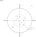
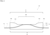
- Fig. 2 shows a cross-section of the ulcer model of the present embodiment
- fig. 3 shows one embodiment of the ulcer model 101.
- the upper surface S1 includes an annular raised surface S10 which is raised in the thickness direction of the model body 10 and a simulated ulcer surface S20 which is a bottom surface of a recessed section surrounded by the raised surface S10.
- the shape of the annular raised surface S10 may, as shown in fig.
- the annular raised surface S10 is a shape that surrounds the simulated ulcer surface S20, there are no particular limitations thereon.
- the outer circumference and the inner circumference of the raised surface S10 to have, each independently, any arbitrary shape selected from among a circle, an ellipse, a polygon, and an indeterminate shape when the raised surface S10 is seen from the upper surface S1.
- the outer circumference of the simulated ulcer surface S20 to have any arbitrary shape selected from among, for example, a circle, an ellipse, a polygon, and an indeterminate shape when the simulated ulcer surface 20 is seen from the upper surface S1.
- the simulated blood vessel 5 extends inside the model body 10 from the outer circumferential surface S11 of the model body 10 to the simulated ulcer surface S20 and is oriented with the outlet opening section 5b positioned on the simulated ulcer surface S20 side.
- the simulated blood vessel 5 may bend at one or more locations.
- the model body 10 in the embodiment shown in fig. 3 is configured from a flat plated-shaped base part 10a including the simulated ulcer surface S20, and a raised part 10b which is provided on the base part 10a and forms the raised surface S10.
- the base part 10a and the raised part 10b may be molded bodies which are molded from the same or different molding materials. Properties such as hardness, etc., of the base part 10a and the raised part 10b can be selected in accordance with the kind of digestive tract anticipated, etc. For example, the hardness of a molded body forming the raised part 10b may be approximately the same as or lower than the hardness of a molded body forming the base part 10a. As shown in fig. 3 , there may be a plurality of simulated blood vessels 5.
- the maximum width of the model body 10 in a direction perpendicular to the thickness direction thereof may be in a range corresponding to the breadth of a general ulcer, and may, for example, be in the range of 10-150 mm.
- the simulated ulcer surface S20 is typically a flat surface located in the center of the upper surface S1. Note that, as described later, the simulated ulcer surface S20 may include a fine projection.
- the simulated ulcer surface S20 corresponds to the bottom surface of the recessed section in the upper layer S1 and is a part replicating an ulcer section in which the mucosal layer is deficient and a section corresponding to the submucosal layer is exposed.
- the maximum width of the simulated ulcer surface S20 may, for example, be in the range of 3-100 mm.
- the raised surface S10 includes, as an apex 10H, a section at which the thickness of the model body 10 is the greatest.
- the thickness of the model body 10 at the apex 10H (that is, the maximum thickness of the model body 10) is not particularly limited and may be approximately 1-30 mm or approximately 2-20 mm.
- the difference between the thickness of the model body 10 at the position of the apex 10H and the thickness of the model body 10 at the simulated ulcer surface S20 is arbitrary, but may be in the range of about 10-90% with respect to the thickness of the model body 10 at the apex 10H.
- the simulated blood vessel 5 passes through the model body 10 and is a passage for supplying simulated blood to the simulated ulcer surface S20 during hemostasis practice.
- the simulated blood vessel 5 may protrude to the outside of the model body 10 on the inlet opening section 5a side.
- the outlet opening section 5b of the simulated blood vessel 5 may be disposed in the vicinity of the inner side of the simulated ulcer surface S20 without reaching as far as the simulated ulcer surface S20.
- the simulated blood vessel 5 can easily be put in communication with the simulated ulcer surface S20, before technique practice, by a procedure such as resecting a section in the outlet opening section 5b vicinity, piercing with a needle, or pinching with tweezers, etc.
- the outlet opening section 5b may, for example, be disposed at a location at a depth of approximately 0.1-5 mm from the simulated ulcer surface S20.
- An end section of the simulated blood vessel 5 may be connected to a syringe filled with simulated blood, and in that case, the simulated blood is supplied to the inside of the simulated blood vessel from the syringe.
- a syringe any arbitrary device, tool, or equipment capable of supplying the simulated blood, for example, a tubular pump, may be used.
- the ulcer model 101 of the present embodiment When the ulcer model 101 of the present embodiment is used, as long as the objective thereof is not inhibited, it is, for example, possible to use colorants such as pigments and dyes, and additives such as perfumes, antioxidizing agents, and antibacterial agents, etc.
- the ulcer model 101 In order to make the ulcer model 101 of the present embodiment closely resemble an organ in a living body, the ulcer model 101 may be colored, with a colorant, in a color that closely resembles the organ in a living body.
- a resin for forming a layer having an appropriate hardness it is possible to use, for example, a hydrous polyvinyl alcohol-based material containing a polyvinyl alcohol and water, or a hydrocarbon-based resin material containing a lipophilic resin and oil.
- the hardness of a molded body can be appropriately adjusted by, for example, the water content of the hydrous polyvinyl alcohol-based material, the amount of oil in the hydrocarbon-based resin material, and/or the amount of ionic liquid therein.
- the ulcer model 101 according to the present embodiment can be produced by a normal molding method.
- the ulcer model 101 may be produced by setting a tube which is to serve as the simulated blood vessel 5 inside a cavity of a mold having a shape corresponding to the upper surface S1 and the lower surface S2 and then molding.
- the molded body of the hydrous polyvinyl alcohol-based material can be formed, for example, by a method in which a molding composition containing a polyvinyl alcohol, a crosslinking agent (boric acid, or the like), water, and an ionic liquid, etc., is poured into a mold and then gelated, or a method in which the same molding composition is poured into a mold and then repeatedly frozen by cooling to below the melting point thereof and melted by heating to the above the melting point to promote gelation.
- the molded article of the hydrocarbon-based resin material can be formed, for example, by a molding method such as extrusion, casting, vacuum molding, and injection molding including multiple colors.
- the ulcer model 101 can be mounted on an upper digestive tract organ (stomach, esophagus, duodenum) model and used to practice endoscopic hemostasis, etc.
- the ulcer model may be fitted in a model-mounting section provided in the digestive tract model or the ulcer model may be attached to an inner wall of the digestive tract model.
- the model-mounting section of the digestive tract model may be a frame or indentation formed where a portion of the wall is deficient, or a model-mounting jig may be attached to the inner wall of the digestive tract model.
- the ulcer model may be attached to the inner wall by using a bond, an adhesive, double-sided tape, etc.
- Examples of techniques including hemostasis include so-called mechanical techniques in which a hemorrhaging ulcer site is gripped by hemostatic forceps or clips, and thermocoagulation techniques such as thermocoagualation using an energy device, etc.
- Examples of energy devices include electric scalpels, ultrasonic scalpels, and high-frequency radio wave scalpels, etc.
- the raw materials and production method used in the examples, etc. are as follows.
- thermoplastic resin composition Using an ethylene-vinyl acetate-based resin (Evaflex EV170, manufactured by Dow-Mitsui Polychemicals) as the thermoplastic resin composition, a tubular structure having a diameter of 1.0 mm and a thickness of 0.25 mm was fabricated by extrusion molding and used as a substrate layer.
- the substrate layer surface underwent surface modification by a corona treatment.
- the corona treatment was carried out by using a corona surface modification evaluation device (TEC-4AX) manufactured by Kasuga Denki, Inc., under conditions of an output of 80 W, a speed of 0.5 m/min., and a clearance between electrode and substrate of 5 mm.
- TEC-4AX corona surface modification evaluation device manufactured by Kasuga Denki, Inc.
- a polythiophene-based conductive polymer dispersion fluid Denatron PT-436 (manufactured by Nagase ChemteX Corporation; pure/alcohol dispersion fluid), was prepared, coated on an outer surface of the substrate layer, dried for 24 hours in a room temperature environment, and used as a simulated blood vessel having a conductive layer with a thickness of 180 nm.
- thermoplastic resin composition having the hydrogenated styrene-based thermoplastic elastomer and oil mixed therein and fusion-molded at 160°C for five minutes at a pressure of 10 MPa.
- a simulated blood vessel was set in the molded ulcer model in the same manner as shown in fig. 2 , 3 , and 4 .
- Example 1 Other than changing the diameter and thickness of the substrate layer, simulated blood vessels and ulcer models were fabricated in the same manner as in Example 1.
- thermoplastic resin composition of the substrate layer to an ethylene-vinyl acetate-based resin (Ultrasen 640)
- a simulated blood vessel and ulcer model were fabricated in the same manner as in Example 1.
- thermoplastic resin composition of the substrate layer to a thermoplastic polyurethane elastomer resin (Elastollan ET 880)
- a simulated blood vessel and ulcer model were fabricated in the same manner as in Example 1.
- thermoplastic resin composition of the substrate layer was changed to a resin composition obtained by blending 45 parts by mass of an adipic acid-based polyester compound (ADEKA CIZER PN-9302) with respect to 100 parts by mass of a vinyl chloride resin (TH-100), a simulated blood vessel and ulcer model were fabricated in the same manner as in Example 1.
- a resin composition obtained by blending 45 parts by mass of an adipic acid-based polyester compound (ADEKA CIZER PN-9302) with respect to 100 parts by mass of a vinyl chloride resin (TH-100) were fabricated in the same manner as in Example 1.
- thermoplastic resin composition of the substrate layer to a hydrogenated styrene-butadiene elastomer resin (DYNARON 1320P)
- DYNARON 1320P hydrogenated styrene-butadiene elastomer resin
- thermoplastic resin composition of the substrate layer to a 1,2-polybutadiene elastomer resin (RB810)
- a simulated blood vessel and ulcer model were fabricated in the same manner as in Example 1.
- Example 1 Other than not forming a conductive layer, a simulated blood vessel and ulcer model were fabricated in the same manner as in Example 1.
- thermoplastic resin composition of the substrate layer to a low density polyethylene resin (B128)
- a simulated blood vessel and ulcer model were fabricated in the same manner as in Example 1.
- thermoplastic resin composition of the substrate layer to a hydrogenated styrene/ethylene/butylene/styrene block resin (DYNARON 8300P)
- DYNARON 8300P hydrogenated styrene/ethylene/butylene/styrene block resin
- thermoplastic resin compositions used in the examples, etc. are as follows.
- a type 5 test piece shape was punched out from a 1.0 mm thick sheet and measurements were performed by using a tensile testing machine (Autograph AG-Xplus, manufactured by Shimadzu Corporation) in an environment of 23 ⁇ 1°C under conditions of a tensile speed of 50.0 mm/min.
- the tensile modulus of elasticity was calculated from the slope of the initial straight line in a stress-strain curve.
- the corona treatment was carried out by using a corona surface modification evaluation device (TEC-4AX) manufactured by Kasuga Denki, Inc., under conditions of an output of 80 W, a speed of 0.5 m/min., and a clearance between electrode and substrate of 5 mm.
- TEC-4AX corona surface modification evaluation device
- the melting point was measured using a differential scanning calorimeter (DSC; DSC 3+ manufactured by Mettler Toledo) in a nitrogen atmosphere at a temperature increase rate of 10°C/min.
- DSC differential scanning calorimeter
- a surface resistivity of 1.0 ⁇ 10 0 ⁇ / ⁇ or more and 1.0 ⁇ 10 3 ⁇ / ⁇ or less was deemed to be excellent; a surface resistivity of more than 1.0 ⁇ 10 3 ⁇ / ⁇ and 1.0 ⁇ 10 6 ⁇ / ⁇ or less was deemed to be good; and a surface resistivity of more than 1.0 ⁇ 10 6 ⁇ / ⁇ was deemed to be poor.
- a hemostasis operation was carried out using an electric scalpel (conditions: bipolar, coagulation mode, 60 W) on a simulated blood vessel eluting simulated blood, and the degree of elution of the simulated blood in the hemostasis operation was visually evaluated. Cases in which hemostasis is replicated by the hemostasis operation were deemed to be excellent and cases in which hemostasis was not replicated were deemed to be poor.
- the simulated blood vessel and ulcer model according to the present invention can be utilized as a practice tool for hemostasis using an energy device.
Landscapes
- Engineering & Computer Science (AREA)
- General Physics & Mathematics (AREA)
- Physics & Mathematics (AREA)
- Health & Medical Sciences (AREA)
- Computational Mathematics (AREA)
- Mathematical Optimization (AREA)
- Medical Informatics (AREA)
- Medicinal Chemistry (AREA)
- Chemical & Material Sciences (AREA)
- Algebra (AREA)
- Theoretical Computer Science (AREA)
- Educational Technology (AREA)
- Mathematical Analysis (AREA)
- General Health & Medical Sciences (AREA)
- Mathematical Physics (AREA)
- Pure & Applied Mathematics (AREA)
- Business, Economics & Management (AREA)
- Educational Administration (AREA)
- Pulmonology (AREA)
- Radiology & Medical Imaging (AREA)
- Laminated Bodies (AREA)
- Instructional Devices (AREA)
- Extrusion Moulding Of Plastics Or The Like (AREA)
Applications Claiming Priority (2)
| Application Number | Priority Date | Filing Date | Title |
|---|---|---|---|
| JP2021079812 | 2021-05-10 | ||
| PCT/JP2022/013431 WO2022239490A1 (fr) | 2021-05-10 | 2022-03-23 | Vaisseau sanguin simulé et modèle d'ulcère l'utilisant |
Publications (3)
| Publication Number | Publication Date |
|---|---|
| EP4338921A1 true EP4338921A1 (fr) | 2024-03-20 |
| EP4338921A4 EP4338921A4 (fr) | 2024-11-06 |
| EP4338921B1 EP4338921B1 (fr) | 2025-10-08 |
Family
ID=84028154
Family Applications (1)
| Application Number | Title | Priority Date | Filing Date |
|---|---|---|---|
| EP22807195.7A Active EP4338921B1 (fr) | 2021-05-10 | 2022-03-23 | Vaisseau sanguin simulé et modèle d'ulcère l'utilisant |
Country Status (6)
| Country | Link |
|---|---|
| US (1) | US12444322B2 (fr) |
| EP (1) | EP4338921B1 (fr) |
| JP (1) | JP7542143B2 (fr) |
| KR (1) | KR102905992B1 (fr) |
| CN (1) | CN117296087A (fr) |
| WO (1) | WO2022239490A1 (fr) |
Families Citing this family (1)
| Publication number | Priority date | Publication date | Assignee | Title |
|---|---|---|---|---|
| JP2025120536A (ja) * | 2024-02-05 | 2025-08-18 | デンカ株式会社 | 模擬臓器 |
Family Cites Families (21)
| Publication number | Priority date | Publication date | Assignee | Title |
|---|---|---|---|---|
| JP4582453B2 (ja) * | 2004-06-17 | 2010-11-17 | ナガセケムテックス株式会社 | 帯電防止性樹脂シート及び電子部品包装用成形体 |
| JP2006116206A (ja) | 2004-10-25 | 2006-05-11 | Koken Co Ltd | 内視鏡用切開剥離術モデル |
| JP4330555B2 (ja) | 2005-05-27 | 2009-09-16 | 日本エー・シー・ピー株式会社 | 人工血管の製造方法 |
| JP5289714B2 (ja) | 2007-02-14 | 2013-09-11 | 株式会社高研 | Esdトレーニングモデル |
| JP5289997B2 (ja) | 2009-02-17 | 2013-09-11 | テルモ株式会社 | 管の内腔部に配置される病変モデル |
| WO2010095519A1 (fr) | 2009-02-17 | 2010-08-26 | テルモ株式会社 | Modèle biologique pour l'apprentissage et procédé pour produire un modèle biologique pour l'apprentissage |
| KR20130020087A (ko) | 2011-08-17 | 2013-02-27 | 실버레이 주식회사 | 인조혈관과 이를 구비한 인조피부, 인조혈관 제어시스템, 및 인조혈관을 구비한 인조피부 제어시스템 |
| JP2015085017A (ja) | 2013-10-31 | 2015-05-07 | オリンパスメディカルシステムズ株式会社 | 内視鏡用トレーニング装置 |
| JP5759055B1 (ja) * | 2014-05-26 | 2015-08-05 | サンアロー株式会社 | 臓器モデル |
| JP2016177237A (ja) | 2015-03-23 | 2016-10-06 | セイコーエプソン株式会社 | 模擬臓器 |
| JP2017032690A (ja) * | 2015-07-30 | 2017-02-09 | セイコーエプソン株式会社 | 模擬臓器 |
| JP6953866B2 (ja) | 2016-08-31 | 2021-10-27 | 株式会社リコー | ハイドロゲル構造体、その製造方法、及び用途 |
| EP3291208B1 (fr) * | 2016-08-31 | 2020-09-30 | Ricoh Company, Ltd. | Structure d'hydrogel, vaisseau sanguin, modèle d'organisme interne, outil de pratique pour procédure médicale et procédé de fabrication de la structure d'hydrogel |
| JP2018102423A (ja) | 2016-12-22 | 2018-07-05 | 株式会社クレハ | 人工血管、及び人工血管の製造方法 |
| JP7107509B2 (ja) * | 2017-06-28 | 2022-07-27 | デンカ株式会社 | 止血を含む手技を練習するために用いられる潰瘍模型、及び、潰瘍模型の使用 |
| JP6694857B2 (ja) * | 2017-09-06 | 2020-05-20 | 信越ポリマー株式会社 | 導電性フィルム及びその製造方法、並びに帯電防止性配管 |
| KR102745809B1 (ko) | 2018-08-30 | 2024-12-20 | 덴카 주식회사 | 도전성 수지 조성물 및 그 성형품 |
| JP2020036784A (ja) | 2018-09-05 | 2020-03-12 | 国立大学法人 岡山大学 | 人工血管 |
| CN110895896A (zh) | 2019-11-27 | 2020-03-20 | 宁波创导三维医疗科技有限公司 | 一种电刀可切割仿生胃肠道手术模型及其制造方法 |
| JP7492236B2 (ja) | 2019-12-23 | 2024-05-29 | デンカ株式会社 | 粘膜組織モデル |
| CN112309217A (zh) | 2020-11-20 | 2021-02-02 | 宁波创导三维医疗科技有限公司 | 一种显微吻合手术训练模型及模型用血管模型制备工艺 |
-
2022
- 2022-03-23 EP EP22807195.7A patent/EP4338921B1/fr active Active
- 2022-03-23 JP JP2023520883A patent/JP7542143B2/ja active Active
- 2022-03-23 US US18/290,076 patent/US12444322B2/en active Active
- 2022-03-23 KR KR1020237041559A patent/KR102905992B1/ko active Active
- 2022-03-23 WO PCT/JP2022/013431 patent/WO2022239490A1/fr not_active Ceased
- 2022-03-23 CN CN202280034117.4A patent/CN117296087A/zh active Pending
Also Published As
| Publication number | Publication date |
|---|---|
| EP4338921A4 (fr) | 2024-11-06 |
| EP4338921B1 (fr) | 2025-10-08 |
| CN117296087A (zh) | 2023-12-26 |
| KR20240004861A (ko) | 2024-01-11 |
| US20240282219A1 (en) | 2024-08-22 |
| JP7542143B2 (ja) | 2024-08-29 |
| KR102905992B1 (ko) | 2025-12-29 |
| WO2022239490A1 (fr) | 2022-11-17 |
| US12444322B2 (en) | 2025-10-14 |
| JPWO2022239490A1 (fr) | 2022-11-17 |
Similar Documents
| Publication | Publication Date | Title |
|---|---|---|
| KR102386977B1 (ko) | 대전 방지성 성형체의 제조 방법 | |
| CN101583671B (zh) | 导电高分子/掺杂剂的有机溶剂分散体及含有该分散体的组合物 | |
| US9624398B2 (en) | Antistatic release agent and antistatic release film | |
| JP5359263B2 (ja) | 電気電子部品封止用樹脂組成物、電気電子部品封止体の製造方法および電気電子部品封止体 | |
| JP7382789B2 (ja) | 導電性離型フィルム | |
| EP4338921A1 (fr) | Vaisseau sanguin simulé et modèle d'ulcère l'utilisant | |
| JP7269816B2 (ja) | 導電性離型フィルム及びその製造方法 | |
| JP6849271B2 (ja) | 導電膜の製造方法 | |
| JP6560570B2 (ja) | 透明導電性粘着シート | |
| JP6694857B2 (ja) | 導電性フィルム及びその製造方法、並びに帯電防止性配管 | |
| JP6829163B2 (ja) | 導電性高分子分散液、導電性フィルム及びその製造方法、並びに帯電防止性容器及びその製造方法 | |
| JP7814257B2 (ja) | 導電性高分子分散液、導電性積層体及びその製造方法 | |
| KR20190016444A (ko) | 도전성 고분자 분산액, 도전성 필름과 그 제조 방법 및 대전 방지성 용기와 그 제조 방법 | |
| JP7825246B2 (ja) | 十二指腸乳頭モデル | |
| JP7341029B2 (ja) | 導電性離型フィルム及びその製造方法 | |
| JP7523372B2 (ja) | 導電性高分子分散液、導電性積層体及びその製造方法 | |
| JP2016172802A (ja) | 帯電防止性成形品の製造方法 | |
| JP7792869B2 (ja) | 導電性高分子分散液、導電性積層体及びその製造方法 | |
| JP7479160B2 (ja) | 導電性高分子分散液の製造方法、及び導電性フィルムの製造方法 | |
| TW202548696A (zh) | 模擬臟器 | |
| JP2024008379A (ja) | 導電性高分子分散液、導電性積層体及びその製造方法 | |
| JP2021048044A (ja) | 導電性フィルム及びその製造方法 |
Legal Events
| Date | Code | Title | Description |
|---|---|---|---|
| STAA | Information on the status of an ep patent application or granted ep patent |
Free format text: STATUS: THE INTERNATIONAL PUBLICATION HAS BEEN MADE |
|
| PUAI | Public reference made under article 153(3) epc to a published international application that has entered the european phase |
Free format text: ORIGINAL CODE: 0009012 |
|
| STAA | Information on the status of an ep patent application or granted ep patent |
Free format text: STATUS: REQUEST FOR EXAMINATION WAS MADE |
|
| 17P | Request for examination filed |
Effective date: 20231113 |
|
| AK | Designated contracting states |
Kind code of ref document: A1 Designated state(s): AL AT BE BG CH CY CZ DE DK EE ES FI FR GB GR HR HU IE IS IT LI LT LU LV MC MK MT NL NO PL PT RO RS SE SI SK SM TR |
|
| DAV | Request for validation of the european patent (deleted) | ||
| DAX | Request for extension of the european patent (deleted) | ||
| REG | Reference to a national code |
Ref country code: DE Ref legal event code: R079 Ref country code: DE Ref legal event code: R079 Ref document number: 602022022785 Country of ref document: DE Free format text: PREVIOUS MAIN CLASS: B29C0039260000 Ipc: G09B0023280000 |
|
| A4 | Supplementary search report drawn up and despatched |
Effective date: 20241009 |
|
| RIC1 | Information provided on ipc code assigned before grant |
Ipc: B29K 101/12 20060101ALN20241002BHEP Ipc: B29L 31/00 20060101ALN20241002BHEP Ipc: B29C 39/26 20060101ALN20241002BHEP Ipc: G09B 23/30 20060101ALI20241002BHEP Ipc: G09B 23/28 20060101AFI20241002BHEP |
|
| GRAP | Despatch of communication of intention to grant a patent |
Free format text: ORIGINAL CODE: EPIDOSNIGR1 |
|
| STAA | Information on the status of an ep patent application or granted ep patent |
Free format text: STATUS: GRANT OF PATENT IS INTENDED |
|
| RIC1 | Information provided on ipc code assigned before grant |
Ipc: B29L 31/00 20060101ALN20250429BHEP Ipc: B29K 101/12 20060101ALN20250429BHEP Ipc: B29C 39/26 20060101ALN20250429BHEP Ipc: G09B 23/30 20060101ALI20250429BHEP Ipc: G09B 23/28 20060101AFI20250429BHEP |
|
| INTG | Intention to grant announced |
Effective date: 20250508 |
|
| GRAS | Grant fee paid |
Free format text: ORIGINAL CODE: EPIDOSNIGR3 |
|
| GRAA | (expected) grant |
Free format text: ORIGINAL CODE: 0009210 |
|
| STAA | Information on the status of an ep patent application or granted ep patent |
Free format text: STATUS: THE PATENT HAS BEEN GRANTED |
|
| AK | Designated contracting states |
Kind code of ref document: B1 Designated state(s): AL AT BE BG CH CY CZ DE DK EE ES FI FR GB GR HR HU IE IS IT LI LT LU LV MC MK MT NL NO PL PT RO RS SE SI SK SM TR |
|
| P01 | Opt-out of the competence of the unified patent court (upc) registered |
Free format text: CASE NUMBER: UPC_APP_5008_4338921/2025 Effective date: 20250828 |
|
| REG | Reference to a national code |
Ref country code: GB Ref legal event code: FG4D Ref country code: CH Ref legal event code: F10 Free format text: ST27 STATUS EVENT CODE: U-0-0-F10-F00 (AS PROVIDED BY THE NATIONAL OFFICE) Effective date: 20251008 |
|
| REG | Reference to a national code |
Ref country code: DE Ref legal event code: R096 Ref document number: 602022022785 Country of ref document: DE |
|
| REG | Reference to a national code |
Ref country code: IE Ref legal event code: FG4D |
|
| REG | Reference to a national code |
Ref country code: NL Ref legal event code: MP Effective date: 20251008 |
|
| REG | Reference to a national code |
Ref country code: AT Ref legal event code: MK05 Ref document number: 1845532 Country of ref document: AT Kind code of ref document: T Effective date: 20251008 |
|
| PG25 | Lapsed in a contracting state [announced via postgrant information from national office to epo] |
Ref country code: NL Free format text: LAPSE BECAUSE OF FAILURE TO SUBMIT A TRANSLATION OF THE DESCRIPTION OR TO PAY THE FEE WITHIN THE PRESCRIBED TIME-LIMIT Effective date: 20251008 |
|
| PG25 | Lapsed in a contracting state [announced via postgrant information from national office to epo] |
Ref country code: ES Free format text: LAPSE BECAUSE OF FAILURE TO SUBMIT A TRANSLATION OF THE DESCRIPTION OR TO PAY THE FEE WITHIN THE PRESCRIBED TIME-LIMIT Effective date: 20251008 |
|
| REG | Reference to a national code |
Ref country code: LT Ref legal event code: MG9D |
|
| PG25 | Lapsed in a contracting state [announced via postgrant information from national office to epo] |
Ref country code: NO Free format text: LAPSE BECAUSE OF FAILURE TO SUBMIT A TRANSLATION OF THE DESCRIPTION OR TO PAY THE FEE WITHIN THE PRESCRIBED TIME-LIMIT Effective date: 20260108 |
|
| PGFP | Annual fee paid to national office [announced via postgrant information from national office to epo] |
Ref country code: DE Payment date: 20260319 Year of fee payment: 5 |
|
| PG25 | Lapsed in a contracting state [announced via postgrant information from national office to epo] |
Ref country code: FI Free format text: LAPSE BECAUSE OF FAILURE TO SUBMIT A TRANSLATION OF THE DESCRIPTION OR TO PAY THE FEE WITHIN THE PRESCRIBED TIME-LIMIT Effective date: 20251008 Ref country code: AT Free format text: LAPSE BECAUSE OF FAILURE TO SUBMIT A TRANSLATION OF THE DESCRIPTION OR TO PAY THE FEE WITHIN THE PRESCRIBED TIME-LIMIT Effective date: 20251008 Ref country code: HR Free format text: LAPSE BECAUSE OF FAILURE TO SUBMIT A TRANSLATION OF THE DESCRIPTION OR TO PAY THE FEE WITHIN THE PRESCRIBED TIME-LIMIT Effective date: 20251008 |
|
| PG25 | Lapsed in a contracting state [announced via postgrant information from national office to epo] |
Ref country code: RS Free format text: LAPSE BECAUSE OF FAILURE TO SUBMIT A TRANSLATION OF THE DESCRIPTION OR TO PAY THE FEE WITHIN THE PRESCRIBED TIME-LIMIT Effective date: 20260108 |
|
| PG25 | Lapsed in a contracting state [announced via postgrant information from national office to epo] |
Ref country code: IS Free format text: LAPSE BECAUSE OF FAILURE TO SUBMIT A TRANSLATION OF THE DESCRIPTION OR TO PAY THE FEE WITHIN THE PRESCRIBED TIME-LIMIT Effective date: 20260208 |
|
| PG25 | Lapsed in a contracting state [announced via postgrant information from national office to epo] |
Ref country code: PT Free format text: LAPSE BECAUSE OF FAILURE TO SUBMIT A TRANSLATION OF THE DESCRIPTION OR TO PAY THE FEE WITHIN THE PRESCRIBED TIME-LIMIT Effective date: 20260209 |
|
| PG25 | Lapsed in a contracting state [announced via postgrant information from national office to epo] |
Ref country code: PL Free format text: LAPSE BECAUSE OF FAILURE TO SUBMIT A TRANSLATION OF THE DESCRIPTION OR TO PAY THE FEE WITHIN THE PRESCRIBED TIME-LIMIT Effective date: 20251008 |
|
| PG25 | Lapsed in a contracting state [announced via postgrant information from national office to epo] |
Ref country code: LV Free format text: LAPSE BECAUSE OF FAILURE TO SUBMIT A TRANSLATION OF THE DESCRIPTION OR TO PAY THE FEE WITHIN THE PRESCRIBED TIME-LIMIT Effective date: 20251008 |