EP4339014A1 - Siège de cabine - Google Patents
Siège de cabine Download PDFInfo
- Publication number
- EP4339014A1 EP4339014A1 EP23198209.1A EP23198209A EP4339014A1 EP 4339014 A1 EP4339014 A1 EP 4339014A1 EP 23198209 A EP23198209 A EP 23198209A EP 4339014 A1 EP4339014 A1 EP 4339014A1
- Authority
- EP
- European Patent Office
- Prior art keywords
- driver
- cab
- seat
- footrest
- side wall
- Prior art date
- Legal status (The legal status is an assumption and is not a legal conclusion. Google has not performed a legal analysis and makes no representation as to the accuracy of the status listed.)
- Pending
Links
Images



Classifications
-
- B—PERFORMING OPERATIONS; TRANSPORTING
- B60—VEHICLES IN GENERAL
- B60N—SEATS SPECIALLY ADAPTED FOR VEHICLES; VEHICLE PASSENGER ACCOMMODATION NOT OTHERWISE PROVIDED FOR
- B60N2/00—Seats specially adapted for vehicles; Arrangement or mounting of seats in vehicles
- B60N2/02—Seats specially adapted for vehicles; Arrangement or mounting of seats in vehicles the seat or part thereof being movable, e.g. adjustable
- B60N2/04—Seats specially adapted for vehicles; Arrangement or mounting of seats in vehicles the seat or part thereof being movable, e.g. adjustable the whole seat being movable
- B60N2/06—Seats specially adapted for vehicles; Arrangement or mounting of seats in vehicles the seat or part thereof being movable, e.g. adjustable the whole seat being movable slidable
-
- B—PERFORMING OPERATIONS; TRANSPORTING
- B60—VEHICLES IN GENERAL
- B60N—SEATS SPECIALLY ADAPTED FOR VEHICLES; VEHICLE PASSENGER ACCOMMODATION NOT OTHERWISE PROVIDED FOR
- B60N2/00—Seats specially adapted for vehicles; Arrangement or mounting of seats in vehicles
- B60N2/02—Seats specially adapted for vehicles; Arrangement or mounting of seats in vehicles the seat or part thereof being movable, e.g. adjustable
- B60N2/04—Seats specially adapted for vehicles; Arrangement or mounting of seats in vehicles the seat or part thereof being movable, e.g. adjustable the whole seat being movable
- B60N2/06—Seats specially adapted for vehicles; Arrangement or mounting of seats in vehicles the seat or part thereof being movable, e.g. adjustable the whole seat being movable slidable
- B60N2/07—Slide construction
- B60N2/0735—Position and orientation of the slide as a whole
- B60N2/0747—Position and orientation of the slide as a whole the opening of the cross section being oriented in a direction different from the vertical, e.g. transversal
-
- B—PERFORMING OPERATIONS; TRANSPORTING
- B60—VEHICLES IN GENERAL
- B60N—SEATS SPECIALLY ADAPTED FOR VEHICLES; VEHICLE PASSENGER ACCOMMODATION NOT OTHERWISE PROVIDED FOR
- B60N2/00—Seats specially adapted for vehicles; Arrangement or mounting of seats in vehicles
- B60N2/02—Seats specially adapted for vehicles; Arrangement or mounting of seats in vehicles the seat or part thereof being movable, e.g. adjustable
- B60N2/04—Seats specially adapted for vehicles; Arrangement or mounting of seats in vehicles the seat or part thereof being movable, e.g. adjustable the whole seat being movable
- B60N2/06—Seats specially adapted for vehicles; Arrangement or mounting of seats in vehicles the seat or part thereof being movable, e.g. adjustable the whole seat being movable slidable
- B60N2/08—Seats specially adapted for vehicles; Arrangement or mounting of seats in vehicles the seat or part thereof being movable, e.g. adjustable the whole seat being movable slidable characterised by the locking device
- B60N2/0831—Movement of the latch
- B60N2/0862—Movement of the latch sliding
- B60N2/0868—Movement of the latch sliding in a transversal direction
-
- B—PERFORMING OPERATIONS; TRANSPORTING
- B60—VEHICLES IN GENERAL
- B60N—SEATS SPECIALLY ADAPTED FOR VEHICLES; VEHICLE PASSENGER ACCOMMODATION NOT OTHERWISE PROVIDED FOR
- B60N2/00—Seats specially adapted for vehicles; Arrangement or mounting of seats in vehicles
- B60N2/24—Seats specially adapted for vehicles; Arrangement or mounting of seats in vehicles for particular purposes or particular vehicles
-
- B—PERFORMING OPERATIONS; TRANSPORTING
- B60—VEHICLES IN GENERAL
- B60N—SEATS SPECIALLY ADAPTED FOR VEHICLES; VEHICLE PASSENGER ACCOMMODATION NOT OTHERWISE PROVIDED FOR
- B60N2/00—Seats specially adapted for vehicles; Arrangement or mounting of seats in vehicles
- B60N2/24—Seats specially adapted for vehicles; Arrangement or mounting of seats in vehicles for particular purposes or particular vehicles
- B60N2/30—Non-dismountable or dismountable seats storable in a non-use position, e.g. foldable spare seats
- B60N2/3038—Cushion movements
- B60N2/304—Cushion movements by rotation only
- B60N2/3045—Cushion movements by rotation only about transversal axis
- B60N2/3047—Cushion movements by rotation only about transversal axis the cushion being hinged at the back-rest
-
- B—PERFORMING OPERATIONS; TRANSPORTING
- B60—VEHICLES IN GENERAL
- B60N—SEATS SPECIALLY ADAPTED FOR VEHICLES; VEHICLE PASSENGER ACCOMMODATION NOT OTHERWISE PROVIDED FOR
- B60N3/00—Arrangements or adaptations of other passenger fittings, not otherwise provided for
- B60N3/06—Arrangements or adaptations of other passenger fittings, not otherwise provided for of footrests
- B60N3/063—Arrangements or adaptations of other passenger fittings, not otherwise provided for of footrests with adjustment systems
-
- B—PERFORMING OPERATIONS; TRANSPORTING
- B61—RAILWAYS
- B61C—LOCOMOTIVES; MOTOR RAILCARS
- B61C17/00—Arrangement or disposition of parts; Details or accessories not otherwise provided for; Use of control gear and control systems
- B61C17/04—Arrangement or disposition of driving cabins, footplates or engine rooms; Ventilation thereof
-
- B—PERFORMING OPERATIONS; TRANSPORTING
- B61—RAILWAYS
- B61D—BODY DETAILS OR KINDS OF RAILWAY VEHICLES
- B61D33/00—Seats
- B61D33/0007—Details; Accessories
- B61D33/0014—Seat frames
- B61D33/0021—Seat frames for adjustable or reclining seats
-
- B—PERFORMING OPERATIONS; TRANSPORTING
- B61—RAILWAYS
- B61D—BODY DETAILS OR KINDS OF RAILWAY VEHICLES
- B61D33/00—Seats
- B61D33/0057—Seats characterised by their mounting in vehicles
Definitions
- the present invention relates to a driver's cab seat for a vehicle driver, in particular a driver's cab folding seat, preferably a driver's cab passenger seat for a passenger, for a rail vehicle, in particular for a center cab locomotive.
- Sliding driver's cab seats are basically known from the prior art.
- the displacement of the driver's cab seats in the direction of travel is usually carried out via a displacement mechanism consisting of a rail-like guide element on the driver's cab body side and a seat-side engagement device, which are coordinated with one another for the continuous and locking longitudinal displacement of the seat relative to the guide rail on the driver's cab body side.
- a major challenge in the design of the driver's cab seats and their displacement mechanism is, on the one hand, that the driver's cab seats must be able to assume different operating positions in order to ensure ergonomic handling and driver's cab operation for the vehicle drivers.
- the various operating positions may also include a passive or parking position in which the cab seat is not used but is moved aside and/or folded.
- driver's cab passenger folding seats which are used to observe the route for a second person, namely a passenger, and do not have the ability to control the vehicle. These seats must be able to be stowed away in as little space as possible when not in use, so that in the event of an evacuation there are no obstacles, especially in the escape route.
- a major challenge in the design of driver's cab seats with footrests is that the footrests can be positioned ergonomically and easily for the respective user in the active operating position and can also be stowed away in the passive or parking position in such a way that they are not are in the way.
- Basic fastening arrangements for passenger seats are, for example, from EP 2 948 339 B1 known to achieve a gradual fine alignment of the passenger seats.
- the EP 2 948 339 B1 does not deal with cab seats, particularly cab seats with footrests.
- An object of the present invention is to remedy the disadvantages of the prior art, in particular to make a driver's cab seat with a footrest more ergonomic to be designed and/or in which the different operating positions can be assumed in a structurally simple manner.
- an in particular displaceable and/or foldable driver's cab seat in particular a driver's cab folding seat, preferably a driver's cab passenger seat, such as a driver's cab passenger folding seat, is provided for a rail vehicle, in particular a center cab locomotive.
- the driver's cab seat is to be arranged in a driver's cab of the rail vehicle and is used by a vehicle driver or a vehicle passenger. Due to the fact that these are seats at a workplace, there are challenges in the arrangement with regard to seating comfort on the one hand and ensuring accessibility to the driver's cab or to a driver's cab arranged in the driver's cab, which contains all the controls for operating the rail vehicle, on the other hand.
- the driver's cab seat according to the invention represents an optimal compromise between accessibility and comfort and also offers the possibility of adjusting the driver's cab seat between different operating positions in an ergonomic, simple manner.
- What is generic for the driver's cab seats according to the invention is that they have both a seat for the operator and a footrest. Particularly with such driver's cab seats with footrests, the above-described compromise between accessibility to the driver's cab and high comfort in the seating position has not yet been satisfactorily solved in the prior art.
- the driver's cab seat comprises a seat and a footrest and can be moved between a sitting position in which an operator can sit on the driver's cab seat and a passive position in which the seat and the footrest are folded away from the sitting position.
- the passive position can also be referred to as a stowage position, since this is intended to accommodate the driver's cab seat in a storage space provided for this purpose in as space-saving a manner as possible, so that the space in the driver's cab occupied by the driver's cab seat in the sitting position is released.
- the passive position can, for example, be arranged essentially below the driver's cab.
- the passive position can be selected such that the driver's cab passenger seat allows access and exit to the driver's cab, in particular so as not to represent an obstacle in the event of an evacuation.
- the driver's cab seat according to the invention is therefore optimized with regard to the compromise between comfort and accessibility of the driver's cab, that, on the one hand, a very comfortable leadership seat is created via the footrest, but this can be folded away in order to meet the accessibility requirements of the driver's cab if necessary. Moving the footrest and the seat from the sitting position into the passive position can, for example, be done together, i.e. by either actuating the footrest or actuating the seat, with the other component being automatically folded away, so to speak, or separately, that is, independently of one another .
- the driver's cab seat is particularly continuously displaceable in the longitudinal direction of the rail vehicle.
- the driver's cab seat can be mounted on a side wall of the driver's cab, in particular in a longitudinally displaceable manner.
- the storage can take place via several storage devices, on the one hand to be able to carry the high weight of the driver's cab seat, if necessary together with the operator sitting on the driver's cab seat, and on the other hand to provide good guidance during the longitudinal displacement.
- the seat and the footrest are coupled to one another in such a way that the footrest follows the seat when the driver's cab seat is displaced longitudinally.
- the footrest moves in particular automatically when the driver's cab seat is moved longitudinally, which is usually initiated by the operator grabbing the seat or a seat back coupled to the seat and moving it into the desired position.
- the seat and the footrest can therefore be moved together.
- the coupling between the seat and the footrest can take place, for example, via a projection, which can be formed, for example, by a support arm structure fastened in the area of the seat in order to achieve or create the necessary distance between the seat and the footrest.
- the driver's cab seat is mounted in a longitudinally displaceable manner on a side wall of the driver's cab via a straight guide, such as a rail guide.
- the linear guide includes a guide device assigned to the seat surface and a guide device assigned to the footrest.
- the double guide device arrangement distributes the load of the seat, including the footrest and, if necessary, the operator, so that on the one hand the load on the individual guide devices is reduced and on the other hand the displacement movement can be as low-friction and smoothly sliding or rolling as possible.
- the management devices can be based on the same management principle, for example through a sliding contact, a rolling contact or the like.
- the guide device assigned to the footrest has a driver's cab-side guide rail, which is arranged at a distance in the longitudinal direction of the rail vehicle and / or in the vertical direction in relation to a driver's cab-side guide rail assigned to the seat surface.
- driver's cab side or “seat side” are to be understood to mean that the respective component is either firmly arranged on the driver's cab, in particular on a wall of the driver's cab, or on the other hand is fixedly arranged on the seat and moves with it during an adjustment movement.
- the guide rails on the driver's cab side can work together with guide carriages on the seat side, in particular on the seat surface side or footrest side, in order to realize the longitudinal movement.
- recirculating ball carriages can be considered.
- the double guide device arrangement consisting of several guide rails on the driver's cab side promotes an easy-to-operate and uniformly moving guide movement of the guide seat along the straight guide.
- the driver's cab seat further comprises a locking mechanism with a plurality of predefined locking positions, in particular arranged at a uniform distance in the longitudinal direction of the rail vehicle, at which the driver's cab seat can lock against a longitudinal displacement.
- the driver's cab seat can, on the one hand, be moved continuously in the longitudinal direction, but on the other hand, it can lock into predefined locking positions, where it is then secured against further displaceability until the locking position is canceled.
- the locking mechanism can be actuated and released, for example manually by an operator, electrically or pneumatically.
- the locking mechanism has a prestressed, in particular spring-loaded, pull lever which can be actuated by an operator and has a locking pin, which is oriented in a direction transversely, in particular perpendicularly, to the side wall of the driver's cab, i.e. in particular in the horizontal direction, for taking the several Rest positions can be moved.
- the locking mechanism it is possible for an operator to, on the one hand, secure the driver's cab seat against longitudinal displaceability, in particular for driving operations, and, on the other hand, to enable the displaceability in order to move the driver's cab seat into different operating positions.
- the multiple locking positions can For example, be realized by recesses or grooves formed in the guide rail, into which the locking bolt can engage, in particular in a form-fitting manner, whereby the further displaceability of the driver's cab seat is prevented. If the locking mechanism is actuated and the locking bolt is released, i.e. removed from the corresponding recess in the guide rail, the security is canceled and the driver's cab seat can be moved.
- the locking bolt is biased in the direction of a locking position for, in particular, automatically assuming the respective locking position.
- the locking bolt can be designed and/or preloaded, in particular spring-loaded, in such a way that the locking bolt snaps directly or automatically into a corresponding recess in the guide rail as soon as the locking bolt reaches the respective axial height of the corresponding recess.
- the seat and the footrest are coupled to one another in such a way that the footrest follows the seat when the seat is folded away from the sitting position.
- the footrest is folded away automatically, so that the operator only has to carry out a single action in order to bring the entire driver's cab seat into the passive position.
- the seat and the footrest are coupled to one another via a particularly elastic coupling device, such as a torsion bar spring or the like. In this respect, the movement imposed on the seat is transferred by the operator to the footrest. The seat and the footrest can therefore be folded away together.
- a pivot axis assigned to the folding movement of the footrest is oriented in the horizontal direction.
- the footrest can be mounted on a side wall of the driver's cab in such a way that its orientation and/or pivot axis can be changed. To increase comfort for the operator, it is helpful to create different settings and orientations for the footrest so that the operator can adjust it as needed.
- a pivot axis assigned to the folding movement of the footrest is arranged at a short distance from a side wall of the driver's cab. Due to the close arrangement of the The swivel axis on the driver's cab side wall ensures that the footrest can be stowed away to save space in the passive position.
- the pivot axis can be arranged approximately in the area of the vertical alignment of a side wall end of the footrest.
- this pivot axis is arranged so close to the side wall that the footrest in the folded-away passive position is arranged in particular flatly parallel to the side wall and/or at a distance of less than 10 cm from the side wall.
- the parallel arrangement of the footrest with respect to the side wall further promotes its space-saving storage.
- a driver's cab for a rail vehicle in particular a center cab locomotive, is provided, which comprises a driver's cab seat designed according to one of the previously described aspects or exemplary embodiments.
- the driver's cab can also have a side wall, which extends in particular essentially in the vertical direction, to which the driver's cab seat is attached and/or is mounted so that it can be moved longitudinally and folded away.
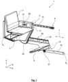
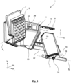
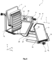
- a driver's seat according to the invention is generally provided with the reference number 1 and, according to the exemplary embodiments according to the accompanying figures, is designed as a longitudinally displaceable folding seat, in particular a passenger folding seat, which is to be arranged in a driver's cab of a center cab locomotive (not shown). or is arranged.
- the driver's cab seat 1 according to the invention Figure 1 comprises a seat 3 and a footrest 5 as well as a seat back 7 arranged adjacent to the seat 3 and is mounted or arranged in a longitudinally displaceable manner on a side wall of the driver's cab via a straight guide 9.
- the driver's cab seat 1 can be moved longitudinally via the linear guide 9, which includes a guide device 11 assigned to the seat surface 3 and a guide device 13 assigned to the footrest 5. Both guide devices 11, 13 are based on the linear guide concept.
- the guide device assigned to the seat 3 is formed as a rail guide comprising a guide rail 15 to be arranged on the side wall of the driver's cab and a seat-side guide carriage 17 that interacts with it, which can be designed, for example, as a recirculating ball carriage.
- the guide device 13 assigned to the footrest 5 includes a guide rail 19 to be fastened or fastened to the side wall of the driver's cab, which cooperates with a footrest-side bearing component 21, such as a rail-like guide carriage, a guide component based on sliding friction or a rolling guide component.
- the footrest 5 and the seat 3 are coupled to one another in such a way, in particular a longitudinal displaceability is designed such that when the driver's cab seat 1 is longitudinally displaced in a longitudinal direction L of the rail vehicle, both the seat 3 and the footrest 5 are moved together , especially parallel and equidistant.
- the footrest 5 and seat 3 can be coupled together via housing structures which are generally provided with the reference number 23.
- a projection such as a cantilevered support arm 27, can extend essentially in the longitudinal direction L away from the seat surface 3 and store or carry the footrest 5.
- the seat surface is essentially oriented in the vertical direction V and is arranged at least in sections parallel to the backrest 7.
- the longitudinal direction L is essentially oriented in a horizontal direction H L , which is perpendicular to a horizontal direction oriented with the reference symbol H T , which essentially indicates a width direction of the driver's cab seat 1 or the cab.
- H L horizontal direction
- H T horizontal direction
- Figures 1 and 4 It can be seen that the footrest 5 is pivoted about a pivot axis S2 and is also brought into a vertical orientation in order to be as space-saving as possible and/or oriented essentially parallel to the side wall. Due to the close arrangement of the pivot axis S2 to the side wall, a particularly space-saving passive position of the driver's seat 1 results.
- S1 indicates the pivot axis of the seat 3.
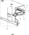
- the Figures 7 and 8th show two different sectional views of the locking mechanism 31, which is responsible for the fact that the driver's cab seat 1 can be locked in several predefined locking positions, in particular arranged at a uniform distance in the longitudinal direction L of the rail vehicle, at which the driver's cab seat 1 is secured against further longitudinal displacement.
- the latching mechanism 31 includes the already mentioned pull lever 29, which an operator has to pull to activate the latching mechanism 29.
- the activation of the locking mechanism 31 is accompanied by a release of the locking or securing of the driver's cab seat against a longitudinal displacement.
- the locking mechanism 31 also has a locking bolt 33 which is preloaded with the pull lever 29, in particular spring-loaded, and which is surrounded by a spring 35 which applies the preload.
- the guide rail 15 to be attached or attached to the side wall of the driver's cab has a recess 37 for the locking bolt 33 per locking position. If the locking bolt 33, as in Figure 7 is shown, engages in the corresponding recess 37 or is snapped into it, the driver's cab seat 1 is secured against longitudinal displacement. To cancel the locking, An operator must operate the pull lever 29 by pulling it away from the side wall in order to pull the bolt 33 out of the recess 37. Due to the spring preload of the bolt 33 in the direction of the engagement or locking position, the bolt 33 can essentially automatically lock into the next recess 37 when it passes over the next recess, provided that the user does not actuate the pull lever 29 any further.
Landscapes
- Engineering & Computer Science (AREA)
- Mechanical Engineering (AREA)
- Transportation (AREA)
- Aviation & Aerospace Engineering (AREA)
- Automation & Control Theory (AREA)
- Seats For Vehicles (AREA)
Applications Claiming Priority (1)
| Application Number | Priority Date | Filing Date | Title |
|---|---|---|---|
| DE102022123980.2A DE102022123980A1 (de) | 2022-09-19 | 2022-09-19 | Führerhaussitz |
Publications (1)
| Publication Number | Publication Date |
|---|---|
| EP4339014A1 true EP4339014A1 (fr) | 2024-03-20 |
Family
ID=88197047
Family Applications (1)
| Application Number | Title | Priority Date | Filing Date |
|---|---|---|---|
| EP23198209.1A Pending EP4339014A1 (fr) | 2022-09-19 | 2023-09-19 | Siège de cabine |
Country Status (2)
| Country | Link |
|---|---|
| EP (1) | EP4339014A1 (fr) |
| DE (1) | DE102022123980A1 (fr) |
Citations (5)
| Publication number | Priority date | Publication date | Assignee | Title |
|---|---|---|---|---|
| EP0132558B1 (fr) * | 1983-07-23 | 1989-06-28 | Rheinmetall GmbH | Véhicule cuirassé |
| DE202010001972U1 (de) * | 2010-02-06 | 2011-06-09 | Hermann Schnierle GmbH, 86368 | Rollstuhlhalterung für Fahrzeuge |
| US20160001786A1 (en) * | 2014-07-03 | 2016-01-07 | Foster-Miller, Inc. | User-centered locomotive crew console |
| EP2948339B1 (fr) | 2013-04-04 | 2018-06-20 | Siemens Aktiengesellschaft | Système de fixation pour élément de finition intérieur au niveau de la caisse d'un véhicule |
| CN114080333A (zh) * | 2019-07-02 | 2022-02-22 | Thk株式会社 | 车厢内的座位排列的变更结构 |
Family Cites Families (3)
| Publication number | Priority date | Publication date | Assignee | Title |
|---|---|---|---|---|
| DE63836C (de) * | A. SCHMIDT in Saalfeld, Saale | Sessel für Locomotivführer | ||
| CH287761A (de) * | 1950-01-11 | 1952-12-15 | Bbc Brown Boveri & Cie | Schienenfahrzeug mit fremder oder eigener Kraftquelle mit verbesserter Sichtmöglichkeit für den Führer. |
| FR2761309B1 (fr) * | 1997-03-28 | 1999-06-11 | Peugeot | Siege d'appoint pour vehicule automobile |
-
2022
- 2022-09-19 DE DE102022123980.2A patent/DE102022123980A1/de active Pending
-
2023
- 2023-09-19 EP EP23198209.1A patent/EP4339014A1/fr active Pending
Patent Citations (5)
| Publication number | Priority date | Publication date | Assignee | Title |
|---|---|---|---|---|
| EP0132558B1 (fr) * | 1983-07-23 | 1989-06-28 | Rheinmetall GmbH | Véhicule cuirassé |
| DE202010001972U1 (de) * | 2010-02-06 | 2011-06-09 | Hermann Schnierle GmbH, 86368 | Rollstuhlhalterung für Fahrzeuge |
| EP2948339B1 (fr) | 2013-04-04 | 2018-06-20 | Siemens Aktiengesellschaft | Système de fixation pour élément de finition intérieur au niveau de la caisse d'un véhicule |
| US20160001786A1 (en) * | 2014-07-03 | 2016-01-07 | Foster-Miller, Inc. | User-centered locomotive crew console |
| CN114080333A (zh) * | 2019-07-02 | 2022-02-22 | Thk株式会社 | 车厢内的座位排列的变更结构 |
Also Published As
| Publication number | Publication date |
|---|---|
| DE102022123980A8 (de) | 2024-06-13 |
| DE102022123980A1 (de) | 2024-03-21 |
Similar Documents
| Publication | Publication Date | Title |
|---|---|---|
| EP3393910B1 (fr) | Système de siège de transport | |
| DE102012112525B4 (de) | Nutzfahrzeugsitz mit doppelarretierbarem Querschlittenteil | |
| EP2001708B1 (fr) | Dispositif de declenchement d'un element tablette d'un systeme de siege pour vehicules de transport de personnes | |
| EP4037967B1 (fr) | Module de siège d'aéronef | |
| EP3090916B1 (fr) | Composant, comprenant un siege et une fixation de siege, destine a etre installe dans un vehicule sur rails, procede de transfert du siege d'une position de rangement dans une position d'utilisation et vehicule sur rail comprenant un tel composant | |
| DE102021209728A1 (de) | Aus einer Dreisitzstellung in eine Zweisitzstellung überführbare Fahrzeugsitzanordnung | |
| EP1777100B1 (fr) | Système de dossier | |
| DE112018006209B4 (de) | Fahrzeugsitz | |
| DE102007055144A1 (de) | Verstaubarer Fahrzeugsitz | |
| DE102008017710A1 (de) | Sitzanordnung für ein Kraftfahrzeug mit einem längsverschiebbaren mittleren Fahrzeugsitz | |
| EP2443033A2 (fr) | Système de siège passager | |
| EP0221229A2 (fr) | Siège rembourré, en particulier pour le montage dans un véhicule mobile à multiples usages | |
| WO2014125055A1 (fr) | Siège de véhicule, en particulier pour une rangée de sièges arrière | |
| EP4339014A1 (fr) | Siège de cabine | |
| EP0313075A2 (fr) | Disposition de sièges-lits pour bus, wagons, avions et bateaux | |
| DE3531992A1 (de) | Verstelleinrichtung fuer eine in ihrer neigung verstellbare kraftfahrzeug-hintersitzlehne | |
| EP1615795B1 (fr) | Dispositif de guidage longitudinal pour un siege de vehicule automobile | |
| WO2024184466A1 (fr) | Mécanisme de libération d'urgence pour un système de siège dans un véhicule | |
| EP1974982A2 (fr) | Dispositif destiné à s'asseoir, en particulier siège de véhicule automobile ou d'avion | |
| DE102012004149B4 (de) | Längseinstellbarer Fahrzeugsitz | |
| EP1754426B1 (fr) | Siège avec repose-jambes extractable | |
| DE69818616T2 (de) | Anordnung für einen ausnehmbaren und in Längsrichtung verstellbaren Sitz im Innenraum eines Kraftfahrzeuges | |
| DE102020122999B4 (de) | Fahrzeugsitz | |
| DE102012112524B4 (de) | Nutzfahrzeugsitz | |
| EP4289665B1 (fr) | Agencement de siège de conducteur pour un chariot de manutention |
Legal Events
| Date | Code | Title | Description |
|---|---|---|---|
| PUAI | Public reference made under article 153(3) epc to a published international application that has entered the european phase |
Free format text: ORIGINAL CODE: 0009012 |
|
| STAA | Information on the status of an ep patent application or granted ep patent |
Free format text: STATUS: THE APPLICATION HAS BEEN PUBLISHED |
|
| AK | Designated contracting states |
Kind code of ref document: A1 Designated state(s): AL AT BE BG CH CY CZ DE DK EE ES FI FR GB GR HR HU IE IS IT LI LT LU LV MC ME MK MT NL NO PL PT RO RS SE SI SK SM TR |
|
| STAA | Information on the status of an ep patent application or granted ep patent |
Free format text: STATUS: REQUEST FOR EXAMINATION WAS MADE |
|
| 17P | Request for examination filed |
Effective date: 20240918 |
|
| RBV | Designated contracting states (corrected) |
Designated state(s): AL AT BE BG CH CY CZ DE DK EE ES FI FR GB GR HR HU IE IS IT LI LT LU LV MC ME MK MT NL NO PL PT RO RS SE SI SK SM TR |
|
| STAA | Information on the status of an ep patent application or granted ep patent |
Free format text: STATUS: EXAMINATION IS IN PROGRESS |
|
| 17Q | First examination report despatched |
Effective date: 20250804 |