EP4339464A1 - Turboverdichter und verfahren zur steuerung davon - Google Patents
Turboverdichter und verfahren zur steuerung davon Download PDFInfo
- Publication number
- EP4339464A1 EP4339464A1 EP22807744.2A EP22807744A EP4339464A1 EP 4339464 A1 EP4339464 A1 EP 4339464A1 EP 22807744 A EP22807744 A EP 22807744A EP 4339464 A1 EP4339464 A1 EP 4339464A1
- Authority
- EP
- European Patent Office
- Prior art keywords
- refrigerant
- impeller
- valve
- compression unit
- turbocompressor
- Prior art date
- Legal status (The legal status is an assumption and is not a legal conclusion. Google has not performed a legal analysis and makes no representation as to the accuracy of the status listed.)
- Pending
Links
- 238000000034 method Methods 0.000 title claims abstract description 32
- 239000003507 refrigerant Substances 0.000 claims abstract description 225
- 230000006835 compression Effects 0.000 claims abstract description 209
- 238000007906 compression Methods 0.000 claims abstract description 209
- 238000001816 cooling Methods 0.000 claims description 18
- 238000002347 injection Methods 0.000 claims description 12
- 239000007924 injection Substances 0.000 claims description 12
- 238000010438 heat treatment Methods 0.000 claims description 11
- 230000000903 blocking effect Effects 0.000 claims description 6
- 230000004308 accommodation Effects 0.000 description 9
- 238000005057 refrigeration Methods 0.000 description 8
- 238000007789 sealing Methods 0.000 description 7
- 239000007788 liquid Substances 0.000 description 6
- 230000004044 response Effects 0.000 description 6
- 230000008901 benefit Effects 0.000 description 5
- 239000012530 fluid Substances 0.000 description 5
- 230000001965 increasing effect Effects 0.000 description 4
- 230000008569 process Effects 0.000 description 4
- 238000010586 diagram Methods 0.000 description 3
- 230000003068 static effect Effects 0.000 description 3
- 230000004323 axial length Effects 0.000 description 2
- 230000020169 heat generation Effects 0.000 description 2
- 238000004519 manufacturing process Methods 0.000 description 2
- 230000004048 modification Effects 0.000 description 2
- 238000012986 modification Methods 0.000 description 2
- 230000009467 reduction Effects 0.000 description 2
- 239000000243 solution Substances 0.000 description 2
- 230000004075 alteration Effects 0.000 description 1
- 238000010276 construction Methods 0.000 description 1
- 230000006866 deterioration Effects 0.000 description 1
- 238000007599 discharging Methods 0.000 description 1
- 230000000694 effects Effects 0.000 description 1
- 238000005516 engineering process Methods 0.000 description 1
- 230000002708 enhancing effect Effects 0.000 description 1
- 230000006872 improvement Effects 0.000 description 1
- 230000006698 induction Effects 0.000 description 1
- 238000009434 installation Methods 0.000 description 1
- 230000003993 interaction Effects 0.000 description 1
- 238000012423 maintenance Methods 0.000 description 1
- 230000007246 mechanism Effects 0.000 description 1
- 230000000116 mitigating effect Effects 0.000 description 1
- 238000005549 size reduction Methods 0.000 description 1
- 238000003756 stirring Methods 0.000 description 1
- 239000000758 substrate Substances 0.000 description 1
- 238000003466 welding Methods 0.000 description 1
Images




Classifications
-
- F—MECHANICAL ENGINEERING; LIGHTING; HEATING; WEAPONS; BLASTING
- F04—POSITIVE - DISPLACEMENT MACHINES FOR LIQUIDS; PUMPS FOR LIQUIDS OR ELASTIC FLUIDS
- F04D—NON-POSITIVE-DISPLACEMENT PUMPS
- F04D17/00—Radial-flow pumps, e.g. centrifugal pumps; Helico-centrifugal pumps
- F04D17/08—Centrifugal pumps
- F04D17/10—Centrifugal pumps for compressing or evacuating
- F04D17/12—Multi-stage pumps
-
- F—MECHANICAL ENGINEERING; LIGHTING; HEATING; WEAPONS; BLASTING
- F04—POSITIVE - DISPLACEMENT MACHINES FOR LIQUIDS; PUMPS FOR LIQUIDS OR ELASTIC FLUIDS
- F04D—NON-POSITIVE-DISPLACEMENT PUMPS
- F04D17/00—Radial-flow pumps, e.g. centrifugal pumps; Helico-centrifugal pumps
- F04D17/08—Centrifugal pumps
- F04D17/10—Centrifugal pumps for compressing or evacuating
- F04D17/12—Multi-stage pumps
- F04D17/122—Multi-stage pumps the individual rotor discs being, one for each stage, on a common shaft and axially spaced, e.g. conventional centrifugal multi- stage compressors
-
- F—MECHANICAL ENGINEERING; LIGHTING; HEATING; WEAPONS; BLASTING
- F04—POSITIVE - DISPLACEMENT MACHINES FOR LIQUIDS; PUMPS FOR LIQUIDS OR ELASTIC FLUIDS
- F04D—NON-POSITIVE-DISPLACEMENT PUMPS
- F04D17/00—Radial-flow pumps, e.g. centrifugal pumps; Helico-centrifugal pumps
- F04D17/08—Centrifugal pumps
- F04D17/10—Centrifugal pumps for compressing or evacuating
- F04D17/12—Multi-stage pumps
- F04D17/14—Multi-stage pumps with means for changing the flow-path through the stages, e.g. series-parallel, e.g. side-loads
-
- F—MECHANICAL ENGINEERING; LIGHTING; HEATING; WEAPONS; BLASTING
- F04—POSITIVE - DISPLACEMENT MACHINES FOR LIQUIDS; PUMPS FOR LIQUIDS OR ELASTIC FLUIDS
- F04D—NON-POSITIVE-DISPLACEMENT PUMPS
- F04D25/00—Pumping installations or systems
- F04D25/02—Units comprising pumps and their driving means
- F04D25/06—Units comprising pumps and their driving means the pump being electrically driven
-
- F—MECHANICAL ENGINEERING; LIGHTING; HEATING; WEAPONS; BLASTING
- F04—POSITIVE - DISPLACEMENT MACHINES FOR LIQUIDS; PUMPS FOR LIQUIDS OR ELASTIC FLUIDS
- F04D—NON-POSITIVE-DISPLACEMENT PUMPS
- F04D27/00—Control, e.g. regulation, of pumps, pumping installations or pumping systems specially adapted for elastic fluids
- F04D27/02—Surge control
-
- F—MECHANICAL ENGINEERING; LIGHTING; HEATING; WEAPONS; BLASTING
- F04—POSITIVE - DISPLACEMENT MACHINES FOR LIQUIDS; PUMPS FOR LIQUIDS OR ELASTIC FLUIDS
- F04D—NON-POSITIVE-DISPLACEMENT PUMPS
- F04D27/00—Control, e.g. regulation, of pumps, pumping installations or pumping systems specially adapted for elastic fluids
- F04D27/02—Surge control
- F04D27/0207—Surge control by bleeding, bypassing or recycling fluids
- F04D27/0215—Arrangements therefor, e.g. bleed or by-pass valves
-
- F—MECHANICAL ENGINEERING; LIGHTING; HEATING; WEAPONS; BLASTING
- F04—POSITIVE - DISPLACEMENT MACHINES FOR LIQUIDS; PUMPS FOR LIQUIDS OR ELASTIC FLUIDS
- F04D—NON-POSITIVE-DISPLACEMENT PUMPS
- F04D27/00—Control, e.g. regulation, of pumps, pumping installations or pumping systems specially adapted for elastic fluids
- F04D27/02—Surge control
- F04D27/0207—Surge control by bleeding, bypassing or recycling fluids
- F04D27/0223—Control schemes therefor
-
- F—MECHANICAL ENGINEERING; LIGHTING; HEATING; WEAPONS; BLASTING
- F04—POSITIVE - DISPLACEMENT MACHINES FOR LIQUIDS; PUMPS FOR LIQUIDS OR ELASTIC FLUIDS
- F04D—NON-POSITIVE-DISPLACEMENT PUMPS
- F04D27/00—Control, e.g. regulation, of pumps, pumping installations or pumping systems specially adapted for elastic fluids
- F04D27/02—Surge control
- F04D27/0269—Surge control by changing flow path between different stages or between a plurality of compressors; load distribution between compressors
-
- F—MECHANICAL ENGINEERING; LIGHTING; HEATING; WEAPONS; BLASTING
- F04—POSITIVE - DISPLACEMENT MACHINES FOR LIQUIDS; PUMPS FOR LIQUIDS OR ELASTIC FLUIDS
- F04D—NON-POSITIVE-DISPLACEMENT PUMPS
- F04D29/00—Details, component parts, or accessories
- F04D29/05—Shafts or bearings, or assemblies thereof, specially adapted for elastic fluid pumps
- F04D29/053—Shafts
-
- F—MECHANICAL ENGINEERING; LIGHTING; HEATING; WEAPONS; BLASTING
- F04—POSITIVE - DISPLACEMENT MACHINES FOR LIQUIDS; PUMPS FOR LIQUIDS OR ELASTIC FLUIDS
- F04D—NON-POSITIVE-DISPLACEMENT PUMPS
- F04D29/00—Details, component parts, or accessories
- F04D29/26—Rotors specially for elastic fluids
- F04D29/28—Rotors specially for elastic fluids for centrifugal or helico-centrifugal pumps for radial-flow or helico-centrifugal pumps
- F04D29/284—Rotors specially for elastic fluids for centrifugal or helico-centrifugal pumps for radial-flow or helico-centrifugal pumps for compressors
- F04D29/286—Rotors specially for elastic fluids for centrifugal or helico-centrifugal pumps for radial-flow or helico-centrifugal pumps for compressors multi-stage rotors
-
- F—MECHANICAL ENGINEERING; LIGHTING; HEATING; WEAPONS; BLASTING
- F04—POSITIVE - DISPLACEMENT MACHINES FOR LIQUIDS; PUMPS FOR LIQUIDS OR ELASTIC FLUIDS
- F04D—NON-POSITIVE-DISPLACEMENT PUMPS
- F04D29/00—Details, component parts, or accessories
- F04D29/40—Casings; Connections of working fluid
- F04D29/42—Casings; Connections of working fluid for radial or helico-centrifugal pumps
- F04D29/4206—Casings; Connections of working fluid for radial or helico-centrifugal pumps especially adapted for elastic fluid pumps
- F04D29/4226—Fan casings
-
- F—MECHANICAL ENGINEERING; LIGHTING; HEATING; WEAPONS; BLASTING
- F04—POSITIVE - DISPLACEMENT MACHINES FOR LIQUIDS; PUMPS FOR LIQUIDS OR ELASTIC FLUIDS
- F04D—NON-POSITIVE-DISPLACEMENT PUMPS
- F04D29/00—Details, component parts, or accessories
- F04D29/58—Cooling; Heating; Diminishing heat transfer
- F04D29/5806—Cooling the drive system
-
- F—MECHANICAL ENGINEERING; LIGHTING; HEATING; WEAPONS; BLASTING
- F05—INDEXING SCHEMES RELATING TO ENGINES OR PUMPS IN VARIOUS SUBCLASSES OF CLASSES F01-F04
- F05D—INDEXING SCHEME FOR ASPECTS RELATING TO NON-POSITIVE-DISPLACEMENT MACHINES OR ENGINES, GAS-TURBINES OR JET-PROPULSION PLANTS
- F05D2210/00—Working fluids
- F05D2210/10—Kind or type
- F05D2210/14—Refrigerants with particular properties, e.g. HFC
Definitions
- the present disclosure relates to a turbocompressor and a method for controlling the same, and more particularly, a turbocompressor having a structure capable of being miniaturized while achieving a high compression ratio by use of an impeller of a three-stage structure, and a method for controlling the same.
- a compressor is applied to a vapor compression type refrigeration cycle (hereinafter, simply referred to as a refrigeration cycle), such as a refrigerator or an air-conditioner.
- a refrigeration cycle such as a refrigerator or an air-conditioner.
- Compressors may be classified into a reciprocal type, a rotary type, a scroll type, and the like according to a method of compressing refrigerant.
- a reciprocal compressor is a compressor in which gas is compressed by a reciprocating motion of a piston within a cylinder
- a scroll compressor is compressor in which a compression chamber is formed between a fixed wrap of a fixed scroll and an orbiting wrap of an orbiting scroll as the orbiting scroll engaged with the fixed scroll, fixed to an inner space of a hermetic case, performs an orbiting motion.
- a turbocompressor (or turbo compressor) is a kind of centrifugal compressor, which executes a compression of gas by centrifugal force which is generated by rotation of wheels of backwardly-curved blades inside a casing.
- the turbocompressor has advantages of large capacity, low noise, low maintenance costs, and the like, as compared to a reciprocal compressor or a screw-type compressor.
- compression gas which is pure without containing oil can be produced.
- a centrifugal turbocompressor includes an impeller and a diffuser decelerating an accelerated flow of fluid (gas, air) to switch the flow to pressure, in order to compress the gas.
- fluid gas, air
- a motor rotates the impeller at high speed, external gas (fluid) is suctioned in an axial direction of the impeller.
- the suctioned fluid is discharged in a centrifugal direction of the impeller.
- the fluid discharged in the centrifugal direction of the impeller is compressed while moving along a passage formed inside the turbocompressor.
- An opposed type turbocompressor among two-stage turbocompressors is configured such that first-stage and second-stage impellers are disposed on both opposite sides of a motor based on the motor.
- This structure is mechanically stable since the impellers and journal bearings that apply a load to a shaft are disposed symmetrically to each other.
- cool liquid refrigerant of low temperature is injected into a motor unit.
- This method has an advantage of lowering temperature of the motor fast and definitely.
- refrigerant of a refrigeration cycle is partially bypassed to be used for cooling the motor, which may disadvantageously lower refrigeration performance of the refrigeration cycle to some extent.
- impellers are disposed on one side surface of the motor.
- refrigerant suctioned into the impellers cools the motor while passing through the motor and then suctioned back into the impellers.
- the disadvantage of the injection cooling of the opposed type is not caused.
- problems of deterioration of efficiency or reliability of an aerodynamic unit due to an introduction of the liquid refrigerant do not occur.
- an operating speed and a maximum compression ratio have a predetermined relationship. Also, there is a predetermined relationship between the operating speed and a flow rate. Due to those characteristics, upon designing the turbocompressor to have three stages or more, it is difficult to set a range of required flow rate in every compression ratio.
- Patent Document 1 EP 2019192850 (February 26, 2020 ) discloses a turbocompressor having a shaft bearing cooling disposition structure.
- Patent Document 1 provides, as a solution for overcoming deformation of a thrust bearing plate due to heat generation in a thrust bearing and a problem due to shaft vibration caused by the deformation, a structure in which a suction refrigerant bypass passage is formed adjacent to the thrust bearing plate to cool a thrust bearing unit, so as to suppress thermal deformation of the thrust bearing plate.
- Patent Document 1 also discloses, with respect to an inlet distributor having an inlet refrigerant passage, a structure in which the inlet distributor is disposed adjacent to the thrust bearing plate to cool it and has a bypass opening. Some of suction refrigerant introduced through the bypass opening cool the thrust bearing plate and rejoin the suction refrigerant.
- Patent Document 1 a guide which distributes suction refrigerant into a first-stage compression unit is difficult to be manufactured and assembled, and efficiency of the compressor is lowered due to flow resistance. Also, depending on operating conditions of the compressor, upon an introduction of refrigerant of high density, if the refrigerant is distributed for the purpose of cooling a bearing, heat generation is caused instead.
- Patent Document 1 refrigerant in a liquid state is injected and stirred well to cool a motor and a bearing unit.
- the liquid refrigerant of high density is expanded by one-time stirring in terms of characteristics of a horizontal type compressor and then introduced into a suction unit.
- Patent Document 2 US 7293954 (November 13, 2007 ) discloses a control system for predicting and suppressing a surge in a turbocompressor.
- a method for controlling a surge hot-gas bypass is used.
- a bypass tube connects a discharge unit and a suction unit, and a bypass valve is applied to open and close the bypass tube.
- Paten Document 2 discloses the characteristics that, when a surge occurrence is determined in the control system for suppressing the surge, a hot-gas bypass valve is open and closed by a predetermined value through a control device.
- Patent Document 2 when the hot-gas bypass is applied, discharge gas of high temperature and high pressure in the discharge unit is mixed with suction gas, which raises suction pressure so as to allow surge avoidance.
- One aspect of the present disclosure is to provide a turbocompressor having a structure that can be compact in size while achieving a high compression ratio by virtue of an impeller with a three-stage structure, and a method for controlling the same.
- Another aspect of the present disclosure is to provide a turbocompressor that employs impellers of a three-stage structure, by which a flow rate range is not reduced while securing a compression ratio, and a method for controlling the same.
- Another aspect of the present disclosure is to provide a turbocompressor having a structure in which only first-stage and second-stage compression units are used for discharge and a third-stage compression unit bypasses refrigerant or guides the refrigerant to flow to a suction part of the first-stage compression unit, so as to reduce an operating speed and minimize a loss, and a method for controlling the same.
- Another aspect of the present disclosure is to provide a turbocompressor having a structure capable of securing a required flow rate range in every compression ratio upon being designed to three stages or more, and a method for controlling the same.
- a turbocompressor that includes a driving unit that is configured to generate rotational power for compressing refrigerant; a shaft that extends in one direction and is disposed in the driving unit to be rotatable by the power generated in the driving unit; and first to third compression units that are disposed on the shaft at one side of the shaft.
- the first compression unit includes a first impeller that is rotated by the power from the driving unit to suction refrigerant exhausted from an evaporator, compress the suctioned refrigerant, and discharge the compressed refrigerant.
- the second compression unit includes a second impeller that is rotated by the power from the driving unit to suction the refrigerant discharged from the first compression unit, compress the suctioned refrigerant, and discharge the compressed refrigerant.
- the third compression unit includes a third impeller that suctions the refrigerant discharged from the second compression unit, compresses the suctioned refrigerant, and discharges the compressed refrigerant to outside or bypasses the refrigerant to the first compression unit.
- the first compression unit may include a first inlet through which the refrigerant exhausted from the evaporator is suctioned.
- the first inlet may be connected to a first bypass passage that communicates with the third impeller to supply refrigerant, and the first bypass passage may have a first valve therein that allows or blocks a flow of the refrigerant from the first inlet to the third impeller.
- the first compression unit may include a first impeller housing in which the first impeller is accommodated, and the first inlet may be formed in one side of the fist impeller housing in a direction parallel to the shaft.
- the second compression unit may include a second outlet through which refrigerant discharged from the second impeller is supplied to the third impeller.
- the third compression unit may include an inflow passage that communicates with the second outlet and through which the refrigerant discharged from the second impeller flows into the third impeller.
- a second valve may be disposed in the second outlet or the inflow passage, and allow or block the flow of the refrigerant discharged from the second impeller to the third impeller.
- the second compression unit may include a second impeller housing in which the second impeller is accommodated, and the second outlet may be disposed in the second impeller housing.
- the third compression unit may include a third volute disposed on a side portion of the third impeller to accumulate and exhaust refrigerant discharged from the third impeller, and a second bypass passage may be defined between the first inlet and the third volute.
- a third valve may be disposed in the second bypass passage, and allow the refrigerant discharged from the third impeller to flow from the third volute to the first inlet or block the flow of the refrigerant.
- a third outlet communicating with an external cycle may be formed in the third volute, and a fourth valve may be disposed in the third outlet.
- the fourth valve may allow or block a flow of the refrigerant discharged from the third impeller to the external cycle.
- the driving unit may have therein a refrigerant inflow passage communicating with the first inlet, and a fifth valve for allowing or blocking an introduction of refrigerant exhausted from the evaporator may be connected to the refrigerant inflow passage.
- a turbocompressor includes a driving unit that is configured to generate rotational power for compressing refrigerant; a shaft that extends in one direction and is disposed in the driving unit to be rotatable by the power generated in the driving unit; first to third compression units that are disposed on the shaft at one side of the shaft; and a control unit that is electrically connected to the driving unit to control operations of the first to third compression units.
- the first compression unit includes a first impeller that is rotated by the power from the driving unit to suction refrigerant exhausted from an evaporator, compress the suctioned refrigerant, and discharge the compressed refrigerant.
- the second compression unit includes a second impeller that is rotated by the power from the driving unit to suction the refrigerant discharged from the first compression unit, compress the suctioned refrigerant, and discharge the compressed refrigerant.
- the third compression unit includes a third impeller that suctions the refrigerant discharged from the second compression unit, compresses the suctioned refrigerant, and discharges the compressed refrigerant to outside or bypasses the refrigerant to the first compression unit.
- the first compression unit may include a first inlet through which the refrigerant exhausted from the evaporator is suctioned.
- the first inlet may be connected to a first bypass passage that communicates with the third impeller to supply refrigerant, and the first bypass passage may have a first valve therein that allows or blocks a flow of the refrigerant from the first inlet to the third impeller.
- the second compression unit may include a second outlet through which refrigerant discharged from the second impeller is supplied to the third compression unit.
- the third compression unit may include an inflow passage that communicates with the second outlet and through which the refrigerant discharged from the second impeller flows into the third impeller.
- a second valve may be disposed in the second outlet or the inflow passage and allow or block the flow of the refrigerant discharged from the second impeller to the third impeller.
- the third compression unit may include a third volute disposed on a side portion of the third impeller to accumulate and exhaust refrigerant discharged from the third impeller, and a second bypass passage may be defined between the first inlet and the third volute.
- the control unit may be electrically connected to the fourth valve, and control the fourth valve to be turned off when a target pressure ratio is not higher than an available pressure ratio or when a surge occurrence is not predicted.
- the control unit may be electrically connected to the second valve, and control the second valve to be turned off when a target pressure ratio is not higher than an available pressure ratio or when a surge occurrence is not predicted.
- a third valve may be disposed in the second bypass passage, and allow the refrigerant discharged from the third impeller to flow from the third volute to the first inlet or block the flow of the refrigerant.
- the control unit may be electrically connected to the third valve, and control the third valve to be turned off when a target pressure ratio is not higher than an available pressure ratio or when a surge occurrence is not predicted, and controls the third valve to be turned on when the target pressure ratio is higher than the available pressure ratio or when the surge occurrence is predicted.
- a third outlet communicating with an external cycle may be formed in the third volute, and a fourth valve may be disposed in the third outlet.
- the fourth valve may allow or block a flow of the refrigerant discharged from the third impeller to the external cycle.
- the control unit may be electrically connected to the fourth valve, and control the fourth valve to be turned off when a target pressure ratio is not higher than an available pressure ratio or when a surge occurrence is not predicted.
- the driving unit may have therein a refrigerant inflow passage communicating with the first inlet, and a fifth valve for allowing or blocking an introduction of the refrigerant exhausted from the evaporator may be disposed in the refrigerant inflow passage.
- the control unit may be electrically connected to the fifth valve, and control the fifth valve to be turned off when a target pressure ratio is not higher than an available pressure ratio or when a surge occurrence is not predicted, perform heating when a target flow rate is not higher than an available flow rate, and control the fifth valve to be turned on when it is possible to respond to an injection load.
- a method for controlling a turbocompressor that includes determining whether or not a target flow rate is higher than an available flow rate; determining whether or not a target pressure ratio is higher than an available pressure ratio; determining whether or not a surge occurrence is predicted; and determining whether to perform cooling or heating.
- the third compression unit may operate when the target pressure ratio is lower than the available pressure ratio, and the first to fifth valves may be turned off when the third compression unit operates, so as to perform an operation responsive to a load such that refrigerant is discharged.
- the second compression unit may operate when the surge occurrence is not predicted, and the second and third valves may be turned off when the second compression unit operates, so as to perform an operation responsive to a load such that refrigerant is discharged.
- first-stage and second-stage compression units can be allowed for discharging refrigerant while a third-stage compression unit can bypass the refrigerant or allow refrigerant to flow to a suction part of the first-stage compression unit. This can decrease an operating speed and thus minimize a loss.
- all the first-stage to third-stage compression units may not sequentially perform compression, but only the first-stage and second-stage compression units can sequentially perform compression and the third-stage compression unit can suction refrigerant or bypass the refrigerant to a cycle, thereby securing an operating range.
- a surge margin valve can be applied in such a manner.
- the surge margin valve may operate to avoid an operating speed upon an occurrence of an insecure operation at a surge point in the turbocompressor according to the present disclosure, or serve as a safety valve only for the turbocompressor as well as a bypass of the cycle, so as to operate appropriately in real time.
- operation characteristics of several valves can be controlled to minimize a problem that a large amount of refrigerant used for cooling at high speed flows into a first-stage inlet and a liquid compression is caused. This can improve reliability.
- a flow rate of the turbocompressor can increase to secure a larger operating range than a choking region. Therefore, a rated capacity can be expanded without increasing an operating speed, such that the turbocompressor can be applied to various products.
- a method of exhausting refrigerant by bypassing the refrigerant from the third-stage compression unit to an external cycle can simplify passages (e.g., pipes), thereby securing an operating range.
- a singular representation may include a plural representation unless it represents a definitely different meaning from the context.
- FIG. 1 is a sectional view illustrating a turbocompressor 100 according to the present disclosure.
- a turbocompressor 100 according to the present disclosure includes a driving unit 120, a shaft 125, and first to third compression units 130, 140, and 180.
- the driving unit 120 allows a generation of rotational driving force (or rotational power) for compressing refrigerant.
- the driving unit 120 includes a stator 120 and a rotor 122, and a detailed description thereof will be described later.
- the shaft 125 extends in one direction, and is rotated by the driving force generated in the driving unit 120.
- the first to third compression units 130, 140, and 180 are installed on the shaft 125 at one side of the shaft 125.
- the first to third compression units 130, 140, and 180 include first to third impellers 131, 141, and 181, respectively, for compressing refrigerant.
- the first compression unit 130 includes a first impeller 131 that is rotated by the driving force applied from the driving unit 120 to suction refrigerant flowed out of an evaporator, compress the suctioned refrigerant, and discharge the compressed refrigerant.
- the second compression unit 140 includes a second impeller 141 that is rotated by the driving force applied from the driving unit 120 to suction the refrigerant discharged from the first compression unit 130, compress the suctioned refrigerant, and discharge the compressed refrigerant.
- the third compression unit 180 includes a third impeller 181 that suctions the refrigerant discharged from the second compression unit 140, compress the suctioned refrigerant, and discharge the compressed refrigerant to outside or bypass the refrigerant to the first compression unit.
- the third compression unit 180 can receive suction refrigerant and bypass the received refrigerant to a housing or cycle, thereby minimizing a loss and securing a wide operating range.
- the third compression unit 180 is configured to compress refrigerant of high density after the compressions in the first and second compression units 130 and 140. Therefore, the first compression unit 130 does not have to compress a relatively large flow rate of refrigerant upon the compression of the refrigerant, and the refrigerant compressed in the third compression unit 180 can be re-supplied to a rear end of an evaporator that is an inlet of the housing, thereby minimizing the loss.
- the compressor can be driven by reducing the operating speed through the first to third compression units 130, 140, and 180, which may result in securing efficiency improvement.
- this method can minimize an operation at a surge point and securing an operating region although the flow rate and the compression ratio are reduced at the same operating speed, compared to the three-stage compression through the first to third compression units 130, 140, and 180.
- the hot-gas bypass is configured to suction two-stage compressed discharge refrigerant back into the first-stage compression unit. This causes a relatively drastic increase in temperature and pressure, which limits a flow rate of the bypass.
- the refrigerant compressed through the third compression unit 180 is re-supplied to the first and second compression units 130 and 140. Therefore, the relative increase in temperature and pressure can be minimized and design margin for surge characteristics that the turbocompressor 100 typically has can be obtained.
- a surge margin valve can be applied in such a manner.
- the surge margin valve may operate to avoid an operating speed upon an occurrence of an insecure operation at the surge point in the turbocompressor 100 according to the present disclosure, or serve as a safety valve only for the turbocompressor 100, in addition to a bypass of a cycle, so as to operate appropriately in real time.
- the turbocompressor 100 may further include a casing 110.
- a driving unit 120 is disposed in an inner space of the casing 110.
- the first compression unit 130 and the second compression unit 140 are installed outside the casing 110, and a shaft 125 is connected between the driving unit 120 and the compression units 130 and 140.
- the embodiment of the present disclosure illustrates an example of the turbocompressor 100 in which the driving unit 120 is disposed in the inner space of the casing 110, the first compression unit 130 and the second compression unit 140 are installed outside the casing 110, and the shaft 125 is connected between the driving unit 120 and the compression units 130 and 140.
- the casing 110 may include a shell 111 having both ends open and formed in a cylindrical shape, and a front frame 112 and a rear frame 113 covering both the open ends of the shell 111.
- a stator 121 of the driving unit 120 to be explained later is fixedly coupled to an inner circumferential surface of the shell 111.
- Shaft holes 112a and 113a through which the shaft 125 to be explained later is inserted are formed through central portions of the front frame 112 and the rear frame 113.
- Radial bearings 151 and 152 that support the shaft 125 in a radial direction may be disposed in the shaft hole 112a of the front frame 112 and the shaft hole 113a of the rear frame 113, respectively.
- a first thrust bearing 153 may be coupled to an inner surface of the front frame 112, and a second thrust bearing 154 may be coupled to an inner surface of the rear frame 113.
- a first axial support plate (thrust runner) 161 and a second axial support plate (thrust runner) 162 may be fixed to the shaft 125 to be explained later to face the first thrust bearing 153 and the second thrust bearing 154, respectively. That is, the first thrust bearing 153 configures a first direction thrust limiting part together with the first axial support plate 161, and the second thrust bearing 154 configures a second direction thrust limiting part together with the second axial support plate 162. Accordingly, the first direction thrust limiting part and the second direction thrust limiting part form thrust bearings in opposite directions, so as to cancel thrusts with respect to rotational elements including the shaft 125.
- the driving unit 120 is configured to generate a rotational driving force (or rotational power) for compressing refrigerant.
- the driving unit 120 includes a stator 121 and a rotor 122.
- the shaft 125 for transferring rotational force of the rotor 122 to the first impeller 131 and the second impeller 141 to be explained later is coupled to a center of the rotor 122.
- the stator 121 may be fixed to an inner circumferential surface of the casing 110 in a press-fitting manner or may be fixed to the casing 110 in a welding manner.
- an outer circumferential surface of the stator 121 may be cut into a D-like shape, to define a passage with the inner circumferential surface of the casing 110 such that a fluid can move.
- the rotor 121 is located inside the stator 121, and spaced apart from the stator 121.
- Balance weights for offsetting an eccentric load which is generated due to the first impeller 131 and the second impeller 141 to be explained later, may be coupled to both axial ends of the rotor 122.
- the balance weights may alternatively be coupled to the shaft 125, without being installed on the rotor 122.
- a refrigerant inflow passage 182f through which refrigerant discharged from an evaporator can be introduced may be defined in the driving unit 120. The structure thereof will be described later.
- the first axial support plate 161 and the second axial support plate (thrust runner) 162 may be used as the balance weights.
- the shaft 125 is press-fitted through the center of the rotor 122. Therefore, the shaft 125 rotates together with the rotor 122 by receiving rotational force, which is generated by interaction between the stator 121 and the rotor 122. The rotational force is transferred to the first impeller 131 and the second impeller 141 to suction, compress, and discharge refrigerant.
- the first axial support plate 161 and the second axial support plate (thrust runner) 162 that are supported in the axial direction by the first and second thrust bearings 153 and 154 disposed on the casing 110 are fixed to both sides of the shaft 125, namely, both sides of the rotor 122. Accordingly, as aforementioned, the first axial support plate 161 and the second axial support plate 162 disposed on the shaft 125 can be supported in the opposite directions by the first thrust bearing 153 and the second thrust bearing 154 disposed on the casing 110, thereby effectively canceling the thrusts generated by the first compression unit 130 and the second compression unit 140.
- the first axial support plate 161 and the second axial support plate 162 may be integrally disposed on both ends of the rotor 122. However, in this case, frictional heat, which is generated in the process that the first axial support plate 161 and the second axial support plate 162 support the shaft 125 in the axial direction, may be transmitted to the rotor 122. If the support plates 161 and 162 are deformed by receiving a load in the axial direction, the rotor 122 may be deformed. Therefore, the first axial support plate 161 and the second axial support plate 162 may preferably be spaced apart from the both ends of the rotor 122.
- the first axial support plate 161 and the second axial support plate 162 may be adjusted in terms of weight or fixed position, so as to be used as the balance weights. In this instance, separate weight balances are not needed on the rotor 122. Thus, the weight of the rotational elements can be reduced and an axial length of the turbocompressor 100 can be shortened. This can reduce the size of the turbocompressor 100.
- first thrust bearing 153 and the second thrust bearing 154 may not be disposed on the front frame 112 and the rear frame 113, but may be alternatively disposed on opposite sides, namely, the first axial support plate 161 and the second axial support plate 162.
- a front fixed plate (not illustrated) and a rear fixed plate (not illustrated) fixed to the casing 110 may further be disposed separately inside the casing 110, namely, between the front frame 112 and the rotor 122 or between the rear frame 113 and the rotor 122, and the first thrust bearing 153 and the second thrust bearing 154 may be disposed on the front fixed plate and the rear fixed plate.
- the axial length of the turbocompressor 100 may be elongated and the number of assembly processes may increase, but reliability can be enhanced as compared to installation of the thrust bearings directly on the casing 110.
- both the first thrust bearing 153 and the second thrust bearing 154 may be disposed on one side of the driving unit 120, namely, on one of a front side or a rear side based on the stator 121.
- the compression unit 130, 140, 180 may be configured as a single compression unit to proceed a single compression, but as illustrated in the embodiment of the present disclosure, may be configured as a plurality of compression units to proceed multi-stage compression.
- the plurality of compression units 130, 140, and 180 are disposed on both sides of the casing 110 based on the driving unit 120, considering the characteristics of the turbocompressor 100 having a great load in the axial direction.
- the plurality of compression units 130, 140, and 180 may preferably be disposed at one side with respect to the driving unit 120, in terms of high efficiency and size reduction.
- the plurality of compression units when the plurality of compression units are disposed to compress refrigerant through multiple stages, the plurality of compression units will be described by referring to as first to third compression units 130, 140, and 180 according to the order of compressing the refrigerant.
- the first compression unit 130 and the second compression unit 140 are consecutively disposed at one side of the casing 110 along the axial direction.
- the first compression unit 130 and the second compression unit 140 include first and second impellers 131 and 141, respectively, disposed to face the same direction such that refrigerant is introduced from the right side.
- the first compression unit 130 includes a first inlet 132b through which refrigerant exhausted from the evaporator can be suctioned.
- the first compression unit 130 may include a first impeller housing 132 for accommodating the first impeller 131, and the first inlet 132b may be formed at one side of the first impeller housing 132.
- FIG. 1 illustrates an example in which the first inlet 132b is formed in parallel to the shaft at the first impeller housing 132 in the vicinity of the center of the turbocompressor 100.
- a first bypass passage 182d is connected to communicate with the first inlet 132b to supply refrigerant to a third impeller 181.
- a first valve 191a may be disposed in the first bypass passage 182d to allow or block the flow of refrigerant from the first inlet 132b to the third impeller 181.
- the first inlet 132b may be formed at one side of the first impeller housing 132 to be in parallel to the shaft.
- the first valve 191a may be understood as a first bypass valve.
- FIG. 1 illustrates an example, on an upper side, in which the first bypass passage 182d is formed in a shape like " ⁇ " in the first impeller housing 132, a second impeller housing 142, and a third impeller housing 182, but the present disclosure may not be limited thereto.
- the first bypass passage 182d may alternatively be formed in any structure as long as it allows the first inlet 132b to communicate with an inflow passage 182f of the third compression unit 180.
- the impellers 131, 141, and 181 of the first compression unit 130, the second compression unit 140, and the third compression unit 180 may be coupled by being accommodated in the impeller housings 132, 142, and 182, respectively. That is, the first impeller 131 of the first compression unit 130 may be accommodated in the first impeller housing 132 and coupled to the shaft 125, the second impeller 141 of the second compression unit 140 may be accommodated in the second impeller housing 142 and coupled to the shaft 125, and the third impeller 181 of the third compression unit 180 may be accommodated in the third impeller housing 182 and coupled to the shaft 125.
- the first impeller 131, the second impeller 141, and the third impeller 181 may be coupled to the shaft 1215 in a manner of being consecutively disposed in one impeller housing.
- the shape of the impeller housing may considerably be complicated.
- the embodiment of the present disclosure illustrates the example of the multi-stage turbocompressor 100 in which the plurality of impellers are consecutively disposed at one side of the driving unit 120 (or casing 110) in the axial direction.
- a first impeller accommodation space 132a in which the first impeller 131 is accommodated is defined in the first impeller housing 132.
- the first inlet 132b which is connected to a suction pipe 115 such that refrigerant is suctioned therethrough from an evaporator of a refrigeration cycle, is formed in one end of the first impeller housing 132.
- a first outlet 132c through which first-stage compressed refrigerant is guided to the second impeller housing 142 to be explained later is formed in another end of the first impeller housing 132.
- the first impeller accommodation space 132a may be formed in a hermetic shape except for the first inlet 132b and the first outlet 132c to fully accommodate the first impeller 131, but may alternatively be formed in a semi-hermetic shape in which a rear surface side of the first impeller 131 is open and the open surface is closed by a front surface of the second impeller housing 142 to be explained later.
- a first diffuser 133 is disposed between the first inlet 132b and the first outlet 132c to be spaced apart a predetermined distance from an outer circumferential surface of a blade portion 131b of the first impeller 131, and a first volute 134 is disposed at a downstream side of the first diffuser 133.
- the first inlet 132b is formed in a center of one axial end of the first diffuser 133, and the first outlet 132c is formed in a downstream side of the first volute 134.
- the first impeller 131 includes a first circular plate portion 131a coupled to the shaft 125, and a plurality of first blade portions 131b formed on a front surface of the first circular plate portion 131a.
- the plurality of first blade portions 131b may be formed in a conical shape on the front surface of the first circular plate portion 131a but the rear surface of the first circulate plate portion 131a may be formed in a flat plate shape to receive back pressure.
- a back pressure plate (not illustrated) coupled to the shaft 125 may be disposed with being spaced apart a predetermined distance from the rear of the first circular plate portion 131a, and a first sealing member (not illustrated) formed in an annular shape may be disposed on the first back pressure plate. Accordingly, a first back pressure space (not illustrated) in which a predetermined amount of refrigerant is filled may be defined between a front surface of the second impeller housing 142 to be explained later and the first back pressure plate at the rear of the first circular plate portion.
- the first back pressure space may be excluded.
- the second compression unit 140 may include a second outlet 142d through which refrigerant discharged from the second impeller 141 can be applied to the third impeller 181.
- the second outlet 1423 may be disposed in the second impeller housing 142.
- the third compression unit 180 may include an inflow passage 182f. The inflow passage 182f may communicate with the second outlet 142d, such that the refrigerant discharged from the second impeller 141 can flow into the third impeller 181.
- a second valve 191b for allowing or blocking the flow of the refrigerant discharged from the second impeller 141 to the third impeller 181 may be disposed in the second outlet 142d or the inflow passage 182f.
- the second valve 191b may be understood as an inflow valve for allowing or blocking the flow of the refrigerant discharged from the second impeller 141 to the third impeller 181.
- FIG. 1 illustrates an example in which the second outlet 142d is disposed in a second volute and the second valve 191b is disposed in the inflow passage 182f.
- the present disclosure may not be limited to this structure, but the second valve 191b may alternatively be disposed at the side of the second outlet 142d.
- a second impeller accommodation space 142a in which the second impeller 141 is accommodated is defined in the second impeller housing 142.
- a second inlet 142b which is connected to the first outlet 132c such that first-stage compressed refrigerant is suctioned therethrough is formed in one end of the second impeller housing 142.
- a second discharge port 142c which is connected to a discharge pipe 116 such that second-stage compressed refrigerant is guided to a condenser of the refrigeration cycle is formed in another end of the second impeller housing 142.
- a second diffuser 143 is disposed between the second inlet 142b and the second discharge port 142c to be spaced apart a predetermined distance from an outer circumferential surface of a blade portion 141b of the second impeller 141, and a second volute 144 is disposed at a downstream side of the second diffuser 143.
- the second inlet 142b is formed in a center of one axial end of the second diffuser 143, and the second discharge port 142c is formed in a downstream side of the second volute 144.
- the second impeller 141 includes a second circular plate portion 141a coupled to the shaft 125, and a plurality of second blade portions 141b formed on a front surface of the second circular plate portion 141a.
- the plurality of second blade portions 141b may be formed in a conical shape on the front surface of the second circular plate portion 141a but the rear surface of the second circulate plate portion 131a may be formed in a flat plate shape to receive back pressure.
- a second back pressure plate 145 coupled to the shaft 125 may be disposed with being spaced apart a predetermined distance from the rear of the second circular plate portion 141a.
- a second sealing groove 145a formed in an annular shape may be formed in the second back pressure plate 145 such that a second sealing member 146 can be inserted therein.
- a second back pressure space (not illustrated) in which a predetermined amount of refrigerant is filled is defined between the second back pressure plate (not illustrated) and the front surface of the casing 110 at the rear of the second circular plate portion 141a. Refrigerant introduced into the second back pressure space partially flows into the second sealing groove (not illustrated) to push the second sealing member (not illustrated) upward, thereby sealing the back pressure space.
- the second back pressure space may be connected to a back pressure passage to be explained later.
- a back pressure adjustment valve for selectively opening and closing the back pressure passage to vary pressure of the second back pressure space depending on an operating speed (i.e., compression ratio) of the compressor may be disposed in the back pressure passage.
- the back pressure passage may be defined through the second impeller housing 142 and the casing 110. That is, a first back pressure passage may be defined in a housing that constitutes a wall body of the second impeller housing 142, and a second back pressure passage communicating with the first back pressure passage may be defined in the front frame 112 of the casing 110.
- the back pressure passage may alternatively be formed in a pipe shape branched from the middle of the discharge pipe, but it may be preferable in view of reduction of the number of components and manufacturing costs that the back pressure passage is defined inside the impeller housing and the front frame.
- the back pressure passage may alternatively be defined by assembling a separate valve frame, in which the back pressure passage is formed, to the front surface of the casing 110.
- the third compression unit 180 is disposed adjacent to the second compression unit 140.
- the third compression unit 180 is installed at one side of an opposite side to a position where the driving unit 120 of the casing 110 is disposed.
- the third impeller 181 of the third compression unit 180 is accommodated in the third impeller housing 182 and coupled to the shaft 125.
- the third impeller 181, as illustrated in FIG. 1 is disposed to face an opposite direction to the first and second impellers 131 and 141.
- a third impeller accommodation space 182a in which the third impeller 181 is accommodated is defined in the third impeller housing 182.
- a third discharge port 182c through which third-stage compressed refrigerant is discharged is formed in a lower side of the third impeller housing 182.
- the third impeller accommodation space 182a may be formed in a hermetic shape except for the third inlet 182b and the third discharge port 182c to fully accommodate the third impeller 181, but may alternatively be formed in a semi-hermetic shape in which a rear surface side of the third impeller 181 is open and the open surface is closed by a rear surface of the second impeller housing 142 to be explained later.
- a third diffuser 183 is disposed between the third inlet 182b and the third discharge port 182c to be spaced apart a predetermined distance from an outer circumferential surface of a blade portion 181b of the third impeller 181, and a third volute 184 is disposed at a downstream side of the third diffuser 183.
- the third inlet 182b is formed in a center of one axial end of the third diffuser 183, and the third discharge port 182c is formed in a downstream side of the third volute 184.
- the third impeller 181 includes a third circular plate portion 181a coupled to the shaft 125, and a plurality of third blade portions 181b formed on a front surface of the third circular plate portion 181a.
- the plurality of third blade portions 181b may be formed in a conical shape on the front surface of the third circular plate portion 181a but the rear surface of the third circulate plate portion 131a may be formed in a flat plate shape to receive back pressure.
- a back pressure plate (not illustrated) coupled to the shaft 125 may be disposed with being spaced apart a predetermined distance from the rear of the third circular plate portion 181a, and a sealing member (not illustrated) formed in an annular shape may be disposed on the back pressure plate. Accordingly, a back pressure space (not illustrated) in which a predetermined amount of refrigerant is filled may be defined between a rear surface of the second impeller housing 142 to be explained later and the back pressure plate at the rear of the third circular plate portion.
- the third compression unit 180 may include a third volute 184 through which refrigerant discharged from the third impeller 181 can be exhausted.
- a second bypass passage 182e may be defined between the first inlet 132b and the third volute 184.
- a third valve 191c may be disposed in the second bypass passage 182e.
- the third valve 191c may allow refrigerant discharged from the third impeller 181 to flow from the third volute 132b to the first inlet 132b or block the flow of the refrigerant.
- the third valve 191c may be understood as a second bypass valve installed in the second bypass passage 182e.
- a third outlet 182g communicating with an external cycle may be formed in the third volute 184.
- a fourth valve 191d may be installed in the third outlet 182g. The fourth valve 191d may allow the refrigerant discharged from the third impeller 181 to flow to the external cycle or block the flow of the refrigerant.
- the fourth valve 191d may be understood as a third bypass valve installed in the third bypass passage 182e.
- FIG. 1 illustrates an example in which the third outlet 182g is formed in a left direction in the third impeller housing 182, the third outlet 182g communicates with the external cycle, and the fourth valve 191d is installed in the third outlet 182g.
- the third outlet 182g communicating with the external cycle may be formed in the third volute 184, and the fourth valve 191d may be installed in the third outlet 182g.
- the third outlet 182g may communicate with the external cycle.
- the fourth valve 191d is installed in the third outlet 182g, in order to secure a flow rate range of 10 % to 100% of partial load at a pressure ratio of 15 or more, all the first-stage to third-stage compression units may not sequentially perform compression, but only the first-stage and second-stage compression units may sequentially perform compression while only the third-stage compression unit performs suction or bypassing to the cycle, thereby securing an operating range.
- turbocompressor 100 having the multi-stage structure in which the plurality of impellers 131, 141, and 181 are consecutively disposed at one axial side with respect to the driving unit 120 (or casing 110) according to the present disclosure.
- the third impeller accommodation space 182a in which the third impeller 181 is accommodated is defined in the third impeller housing 182.
- An inflow passage 182f is defined in one end of the third impeller housing 182 to receive refrigerant discharged from the second compression unit 140.
- the third outlet 182g and the third discharge port 182c through which refrigerant compressed by the third impeller 181 is exhausted are formed in another end of the third impeller housing 182.
- the driving unit 120 may include a refrigerant inflow passage 182f that can communicate with the first inlet 132b, and a fifth valve 191e may be connected to the refrigerant inflow passage 182f.
- the refrigerant inflow passage 182f may thusly be formed in at least one direction, for example.
- the fifth valve 191e may be understood as an injection valve through which refrigerant supplies from the evaporator into the turbocompressor 100.
- the refrigerant inflow passage 182f is defined in the stator 121 of the driving unit 120 .
- the refrigerant inflow passage 182f is formed in a diagonal direction of the stator 121, but is not limited to this.
- FIG. 1 illustrates the example in which an inlet port communicating with the refrigerant inflow passage 182f is formed in the casing 110 and the fifth valve 191e is installed in the inlet port.
- the fifth valve 191e may allow or block the flow of the refrigerant discharged from the evaporator into the turbocompressor 100.
- a valve space (not illustrated) having a predetermined depth in a radial direction may be defined in the front frame 112 of the casing 110, and a back pressure valve (not illustrated) may be inserted into the valve space.
- a valve spring (not illustrated) for elastically supporting the back pressure valve may be disposed between the valve space and the back pressure valve.
- a second back pressure hole through which the valve space communicates with the inner space of the casing 110 may be formed at one side of a first back pressure hole (not illustrated).
- the second back pressure hole is formed more inward than the first back pressure hole, namely, closer to a center side than the first back pressure hole, so as to be open when receiving higher pressure than pressure applied to the first back pressure hole, in case where the back pressure valve is open by pressure.
- the second back pressure hole may be formed at the same position as the first back pressure hole, namely, a position where the first back pressure hole and the second back pressure hole are open and closed at the same time, or may be formed more outward than the first back pressure hole.
- the back pressure valve may be configured as a ball valve or a piston valve.
- the back pressure valve may have three positions depending on a difference between force by pressure of refrigerant introduced through the back pressure passage and force by elastic force of an elastic member. That is, the back pressure valve may have a first position at which both the first back pressure hole and the second back pressure hole are closed, a second position where the first back pressure hole is open and the second back pressure hole is closed, and a third position where both the first back pressure hole and the second back pressure hole are open.
- a valve spring may be configured as a compression coil spring and disposed between an inner surface of the back pressure valve and the valve space.
- the valve spring may be configured as a tension coil spring and disposed between an outer side of the back pressure valve and the valve space.
- the aforementioned embodiment illustrates that the first back pressure passage is connected to a discharge side, namely, the second discharge port of the second compression unit 140, but in some cases, may alternatively be connected to a discharge side of the first compression unit. Even in this case, the basic configurations of the valve space and the back pressure valve may be equal to those of the previous embodiment.
- the scroll compressor 100 may operate as follows.
- Refrigerant that has passed through the evaporator of the refrigeration cycle is introduced into the first impeller accommodation space 132a through the suction pipe and the first inlet 132b.
- the refrigerant increases in static pressure and simultaneously obtains centrifugal force while moving along the blade portions 131b of the first impeller 131.
- the refrigerant then passes through the first diffuser 133.
- the centrifugally-compressed high temperature and high pressure refrigerant is accumulated in the first volute 134 and discharged through the first outlet 132c.
- the refrigerant discharged from the first outlet 132c is transferred to the second impeller 141 through the second inlet 142b. During this, the refrigerant increases in static pressure again and simultaneously obtains the centrifugal force in the second impeller 141. The refrigerant then passes through the second diffuser 143.
- the refrigerant passing through the second diffuser 143 is compressed up to desired pressure by the centrifugal force.
- the second-stage compressed high temperature and high pressure refrigerant is accumulated in the second volute 144 and discharged to the condenser through the second discharge port 142c and a discharge pipe (not illustrated). This series of processes are repeatedly performed.
- the refrigerant that has passed through the second diffuser 143 and accumulated in the second volute 144 is partially supplied to the third compression unit 180.
- the refrigerant supplied to the third compression unit 180 flows along the inflow passage 182f of the third compression unit 180, and flows into the third impeller accommodation space 182a through the third inlet 182b.
- the refrigerant is transferred to the third impeller 181.
- the refrigerant increases in static pressure again and simultaneously obtains centrifugal force in the third impeller 181, and then passes through the second diffuser 183.
- the refrigerant passing through the third diffuser 183 is compressed up to desired pressure by the centrifugal force.
- the third-stage compressed high temperature and high pressure refrigerant is accumulated in the third volute 184 and partially discharged to the condenser through the third discharge port 182c and the discharge pipe (not illustrated). This series of processes are repeatedly performed.
- Another part of the refrigerant accumulated in the third volute 184 may be supplied to the external cycle through the third outlet 182g.
- still another part of the refrigerant accumulated in the third volute 184 may flow along the second bypass passage 182e under the control of the control unit 170 to be explained later so as to be supplied to the first compression unit 130 again.
- the first impeller 131 and the second impeller 141 receive a thrust pushed rearward by the refrigerant suctioned through the first inlet 132b and the second inlet 142b of the impeller housings 132 and 142.
- the second impeller 141 receives a considerably great rearward thrust as the refrigerant, first-stage compressed by the first impeller 131, is introduced through the second inlet 142b.
- the rearward thrust is prevented by a first thrust bearing 153 and a second thrust bearing 154 disposed inside the casing 110, such that the first impeller 131 and the second impeller 141 are suppressed from being pushed rearward together with the shaft 125.
- the impeller 131 and the second impeller 141 can receive thrust rearward, and also the third impeller 181 can receive the thrust rearwards. Therefore, the thrust of the first and second impellers 131 and 141 and the thrust of the third impeller 181 can be offset to each other, thereby reducing a load applied to the thrust bearing. This can reduce the size of the thrust bearing and decrease the frictional loss due to the thrust bearing, thereby enhancing the efficiency of the compressor.
- an amount of heat generated from the driving unit 120 may increase, but bypassed refrigerant can partially be induced into the inner space of the casing 110 to cool the driving unit 120. This can improve performance of the driving unit 120 and enhance the efficiency of the compressor.
- FIG. 4 is a block diagram illustrating electrical connection relationship of the control unit 170 with the driving unit 120, the first to third compression units 130, 140, and 180 and the first to fifth valves 191a, 191b, 191c, 191d, and 191e.
- the turbocompressor 100 may further include the control unit 170.
- the control unit 170 may operate or stop (turn on or off) the turbocompressor 100 based on a target flow rate, an available flow rate, a target pressure ratio, and an available pressure ratio of the turbocompressor 100.
- control unit 170 may be configured to include a controller or substrate on which a CPU and the like are mounted, but may not be limited thereto.
- the control unit 170 may also be understood as a configuration in which various logics or programs associated with a control method to be explained later can be stored and utilized.
- the control unit 170 is electrically connected to each of the driving unit 120, the first to third compression units 130, 140, and 180, and the first to fifth valves 191a, 191b, 191c, 191d, and 191e, and this example is illustrated in FIG. 4 .
- control unit 170 may turn on or off the first to fifth valves 191a, 191b, 191c, 191d, and 191e or control the second or third compression unit 140 or 180 to compress refrigerant, so as to respond to a load.
- a method for controlling the turbocompressor (S100, S200, and S300) according to the present disclosure is configured such that the control unit 170 controls the turbocompressor 100 to be driven or stopped (turned on or off) based on a target flow rate, an available flow rate, a target pressure ratio, and an available pressure ratio of the turbocompressor 100.
- the turbocompressor control method includes determining whether or not a target flow rate is higher than an available flow rate (S10, S210, S310), determining whether or not a target pressure ratio is higher than an available pressure ratio (S20, S220, S320), determining whether or not a surge occurrence is predicted (S50, S250, S350), and determining whether to perform cooling or heating (S30, S230, S330).
- the turbocompressor control method (S100, S200, and S300) according to the present disclosure, upon each of an operation at a low flow rate and high pressure ratio, an operation at a low flow rate and mid-pressure ratio, or an operation at a high flow rate and low pressure ratio, the first to fifth valves 191a, 191b, 191c, 191d, and 191e may be turned on or off or the second or third compression unit 140 or 180 may perform compression of refrigerant, to deal with the load.
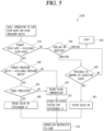
- FIG. 5 is a flowchart illustrating a step (S100) of performing an operation at a low flow rate and high pressure ratio in the turbocompressor 100 according to the present disclosure.
- the control unit 170 determines whether or not a target flow rate is higher than an available flow rate (S10). When the target flow rate is higher than the available flow rate (YES), the control unit 170 determines whether or not a target pressure ratio is higher than an available pressure ratio (S20). When the target flow rate is lower than the available flow rate (No), the control unit 170 determines whether to perform cooling or heating (S30).
- control unit 170 determines whether or not it is possible to respond to an injection load (S40). When it is possible to respond to the injection load (Yes), the control unit 170 turns the fifth valve 191e on (S43) to perform an operation in response to the load (S70).
- the control unit 170 determines whether or not the target pressure ratio is higher than the available pressure ratio (S20). When the target pressure ratio is higher than the available pressure ratio (YES), the control unit 170 predicts whether or not a surge occurs (S50).
- the third compression unit 180 operates (S55).
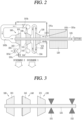
- the control unit 170 turns off the first to fifth valves 191a, 191b, 191c, 191d, and 191e (S57). In this case, Discharge 2 in FIG. 2 is performed and also an operation responsive to the load is performed (S70).
- the third valve 191c is turned on (S60), to perform the operation responsive to the load (S70).
- the third compression unit 180 operates (S55).
- the control unit 170 turns off the first to fifth valves 191a, 191b, 191c, 191d, and 191e (S57). In this case, Discharge 2 in FIG. 2 is performed and also the operation responsive to the load is performed (S70).
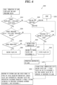
- FIG. 6 is a flowchart illustrating a step (S200) of performing an operation at a low flow rate and mid-pressure ratio in the turbocompressor 100 according to the present disclosure.
- the control unit 170 determines whether or not a target flow rate is higher than the available flow rate (S210). When the target flow rate is higher than the available flow rate (YES), the control unit 170 determines whether or not a target pressure ratio is higher than an available pressure ratio (S220). When the target flow rate is lower than the available flow rate (NO), the control unit 170 determines whether to perform cooling or heating (S230).
- control unit 170 determines whether or not it is possible to respond to an injection load (S240). When it is possible to respond to the injection load (YES), the control unit 170 turns the fifth valve 191e on (S243) to perform an operation in response to the load (S270).
- the control unit 170 determines whether or not the target pressure ratio is higher than the available pressure ratio (S220). When the target pressure ratio is higher than the available pressure ratio (Yes), the control unit 170 predicts whether or not a surge will occur (S250).
- control unit 170 determines whether or not the target pressure ratio is higher than the available pressure ratio (S220). When the target pressure ratio is lower than the available pressure ratio (NO), the second compression unit 140 operates (S255). When the second compression unit 140 operates, the third valve 191c is turned off (S257). In this case, Discharge 1 in FIG. 2 is performed and also the operation responsive to the load is performed (S270).
- the third valve 191c is turned on (S260), to perform the operation responsive to the load (S270).
- the second compression unit 140 operates (S255).
- the third valve 191c is turned off (S257). In this case, Discharge 1 in FIG. 2 is performed and also the operation responsive to the load is performed (S270).
- the second compression unit 140 When the second compression unit 140 operates (S255), the second valve 191b is turned off and the first valve 191a is turned on in the third compression unit 180. Also, Discharge 2 in FIG. 2 may be performed or the fourth valve 191d may be turned on to perform the operation responsive to the load (S256).
- a discharge backflow in a whole system can be suppressed by a pressure difference between Discharge 1 and Discharge 2 in FIG. 2 , an operation response to a system load can be performed, and an occurrence of a surge in a refrigerant passage can be avoided.
- a backflow preventing valve for example, a check valve
- a differential pressure valve may be disposed.
- FIG. 7 is a flowchart illustrating a step (S300) of performing an operation at a high flow rate and low pressure ratio in the turbocompressor 100 according to the present disclosure.
- the control unit 170 determines whether or not a target flow rate is higher than an available flow rate (S310). When the target flow rate is higher than the available flow rate (YES), the control unit 170 determines whether or not a target pressure ratio is higher than an available pressure ratio (S320). When the target flow rate is lower than the available flow rate (NO), the control unit 170 determines whether to perform cooling or heating (S330).
- the third compression unit 180 When it is determined to perform cooling, it is determined whether or not the third compression unit 180 is able to respond to the flow rate (S333). When the response is unable (NO), the operation of the turbocompressor 100 is stopped (S335). On the other hand, when the third compression unit 180 is able to respond to the flow rate (YES), the second valve 191b is turned off and the first valve 191a is turned on in the third compression unit 180. Also, Discharge 2 in FIG. 2 may be performed or the fourth valve 191d may be turned on to perform the operation responsive to the load (S356).
- the control unit 170 determines whether or not it is possible to respond to an injection load (S340). When it is possible to respond to the injection load (YES), the control unit 170 turns the fifth valve 191e on (S343) to perform an operation in response to the load (S370). When it is impossible to respond to the injection load (NO), the operation is stopped (S335).
- control unit 170 determines whether or not the target pressure ratio is higher than the available pressure ratio (S320). When the target pressure ratio is higher than the available pressure ratio (YES), the control unit 170 predicts whether or not a surge will occur (S350).
- the third valve 191c is turned on (S360), to perform the operation responsive to the load (S370).
- the second compression unit 140 operates (S355).
- the second and third valves 191b and 191c are turned off. In this case, Discharge 1 in FIG. 2 is performed (S357) and also the operation responsive to the load is performed (S370).
- the second compression unit 140 When the second compression unit 140 operates (S355), the second valve 191b is turned off and the first valve 191a is turned on in the third compression unit 180. Also, Discharge 2 in FIG. 2 may be performed or the fourth valve 191d may be turned on to perform the operation responsive to the load (S356).
- a discharge backflow in a whole system can be suppressed by a pressure difference between Discharge 1 and Discharge 2 in FIG. 2 , an operation response to a system load can be performed, and an occurrence of a surge in a refrigerant passage can be avoided.
- a backflow preventing valve for example, a check valve
- a differential pressure valve may be disposed.
- the scroll compressor 100 and the method for controlling the same are not limited to the configuration and the method of the embodiments described above, but the embodiments may be configured such that all or some of the embodiments are selectively combined so that various modifications can be made.
- the present disclosure can be applied to a turbocompressor and a method for controlling the same.
Landscapes
- Engineering & Computer Science (AREA)
- Mechanical Engineering (AREA)
- General Engineering & Computer Science (AREA)
- Life Sciences & Earth Sciences (AREA)
- Sustainable Development (AREA)
- Physics & Mathematics (AREA)
- Thermal Sciences (AREA)
- Structures Of Non-Positive Displacement Pumps (AREA)
Applications Claiming Priority (2)
| Application Number | Priority Date | Filing Date | Title |
|---|---|---|---|
| KR1020210061528A KR102548667B1 (ko) | 2021-05-12 | 2021-05-12 | 터보 압축기 및 이를 제어하는 방법 |
| PCT/KR2022/006567 WO2022240096A1 (ko) | 2021-05-12 | 2022-05-09 | 터보 압축기 및 이를 제어하는 방법 |
Publications (2)
| Publication Number | Publication Date |
|---|---|
| EP4339464A1 true EP4339464A1 (de) | 2024-03-20 |
| EP4339464A4 EP4339464A4 (de) | 2025-05-14 |
Family
ID=84029285
Family Applications (1)
| Application Number | Title | Priority Date | Filing Date |
|---|---|---|---|
| EP22807744.2A Pending EP4339464A4 (de) | 2021-05-12 | 2022-05-09 | Turboverdichter und verfahren zur steuerung davon |
Country Status (3)
| Country | Link |
|---|---|
| EP (1) | EP4339464A4 (de) |
| KR (1) | KR102548667B1 (de) |
| WO (1) | WO2022240096A1 (de) |
Cited By (1)
| Publication number | Priority date | Publication date | Assignee | Title |
|---|---|---|---|---|
| US12504021B2 (en) | 2023-02-16 | 2025-12-23 | Ihi Corporation | Compressor with bypass for interstage passage |
Families Citing this family (1)
| Publication number | Priority date | Publication date | Assignee | Title |
|---|---|---|---|---|
| KR102881648B1 (ko) * | 2023-05-02 | 2025-11-05 | 두원중공업(주) | 터보 압축기 |
Family Cites Families (13)
| Publication number | Priority date | Publication date | Assignee | Title |
|---|---|---|---|---|
| DE446239C (de) * | 1923-03-06 | 1927-06-29 | Erste Bruenner Maschinen Fab | Kreiselverdichter mit mehreren Teilverdichtern |
| US4618310A (en) * | 1984-06-07 | 1986-10-21 | Exxon Research & Engineering Co. | Method of multi-stage compressor surge control |
| JPH1089287A (ja) * | 1996-09-17 | 1998-04-07 | Hitachi Ltd | ターボ圧縮機およびその容量制御方法 |
| JP2000291597A (ja) * | 1999-04-01 | 2000-10-17 | Ebara Corp | 冷凍機用多段圧縮機における容量制御装置 |
| IL136921A (en) * | 2000-06-22 | 2004-07-25 | Ide Technologies Ltd | Arrangement for multi-stage heat pump assembly |
| DE10261790B4 (de) * | 2002-12-23 | 2006-09-07 | Robert Bosch Gmbh | Strömungsmaschinenanordnung |
| US7293954B2 (en) | 2004-12-30 | 2007-11-13 | Mitsubishi Heavy Industries, Ltd. | Centrifugal compressor for turbo chiller, turbo chiller, and control method therefor |
| JP2009024582A (ja) * | 2007-07-19 | 2009-02-05 | Ihi Corp | ガス圧縮装置及びガス圧縮装置の制御方法 |
| JP2009270797A (ja) | 2008-05-09 | 2009-11-19 | Daikin Ind Ltd | 冷凍装置 |
| US10184701B2 (en) * | 2011-09-16 | 2019-01-22 | Danfoss A/S | Motor cooling and sub-cooling circuits for compressor |
| KR20180115575A (ko) * | 2017-04-13 | 2018-10-23 | 엘지전자 주식회사 | 터보 압축기 |
| KR102518300B1 (ko) * | 2018-03-06 | 2023-04-05 | 한화파워시스템 주식회사 | 터보 압축기 |
| CN112032091A (zh) * | 2020-08-13 | 2020-12-04 | 中天合创能源有限责任公司化工分公司 | 一种压缩机石墙线防喘振控制系统 |
-
2021
- 2021-05-12 KR KR1020210061528A patent/KR102548667B1/ko active Active
-
2022
- 2022-05-09 EP EP22807744.2A patent/EP4339464A4/de active Pending
- 2022-05-09 WO PCT/KR2022/006567 patent/WO2022240096A1/ko not_active Ceased
Cited By (1)
| Publication number | Priority date | Publication date | Assignee | Title |
|---|---|---|---|---|
| US12504021B2 (en) | 2023-02-16 | 2025-12-23 | Ihi Corporation | Compressor with bypass for interstage passage |
Also Published As
| Publication number | Publication date |
|---|---|
| KR20220153925A (ko) | 2022-11-21 |
| WO2022240096A1 (ko) | 2022-11-17 |
| KR102548667B1 (ko) | 2023-06-28 |
| EP4339464A4 (de) | 2025-05-14 |
Similar Documents
| Publication | Publication Date | Title |
|---|---|---|
| EP3348839B1 (de) | Turboverdichter | |
| EP4339464A1 (de) | Turboverdichter und verfahren zur steuerung davon | |
| KR100414110B1 (ko) | 터보 압축기의 베어링 냉각구조 | |
| US11698074B2 (en) | Turbo compressor and turbo chiller including the same | |
| JP7204524B2 (ja) | 圧縮機 | |
| JP2016176359A (ja) | 圧縮機駆動用モータおよびその冷却方法 | |
| WO2013168194A1 (ja) | 密閉形圧縮機及びヒートポンプ装置 | |
| EP1491769B1 (de) | Vorrichtung mit einem Druckpulsationsdämpfer und einen Durchgang bildendes Gehäuse | |
| CN109996966A (zh) | 两级离心压缩机 | |
| KR20220159795A (ko) | 터보 압축기 | |
| KR20240174369A (ko) | 터보 압축기 | |
| KR20260009793A (ko) | 축방향베어링 및 이를 적용한 터보 압축기 및 이를 구비한 냉동사이클장치 | |
| KR100724452B1 (ko) | 용량 가변형 로터리 압축기 | |
| KR100273380B1 (ko) | 터보 압축기 | |
| KR102877008B1 (ko) | 터보 압축기 | |
| EP4484752A1 (de) | Schraubenverdichter und gefriergerät | |
| CN224214433U (zh) | 叶轮、压缩机及电器设备 | |
| KR100296306B1 (ko) | 터보 압축기의 가스베어링 구조 | |
| WO2025212238A1 (en) | Economizer flow and inlet guide vane configurations for refrigerant compressor | |
| KR20240132867A (ko) | 터보 압축기 및 이를 구비한 냉동사이클장치 | |
| KR100273369B1 (ko) | 터보압축기의 구동축 구조 | |
| KR100279606B1 (ko) | 터보 압축기의 베어링 서포터 | |
| KR100349982B1 (ko) | 터보 압축기용 전자석 밸브 및, 그를 구비한 터보압축기 | |
| KR101176951B1 (ko) | 용량 가변형 로터리 압축기 | |
| CN119096052A (zh) | 涡旋压缩机 |
Legal Events
| Date | Code | Title | Description |
|---|---|---|---|
| STAA | Information on the status of an ep patent application or granted ep patent |
Free format text: STATUS: THE INTERNATIONAL PUBLICATION HAS BEEN MADE |
|
| PUAI | Public reference made under article 153(3) epc to a published international application that has entered the european phase |
Free format text: ORIGINAL CODE: 0009012 |
|
| STAA | Information on the status of an ep patent application or granted ep patent |
Free format text: STATUS: REQUEST FOR EXAMINATION WAS MADE |
|
| 17P | Request for examination filed |
Effective date: 20231212 |
|
| AK | Designated contracting states |
Kind code of ref document: A1 Designated state(s): AL AT BE BG CH CY CZ DE DK EE ES FI FR GB GR HR HU IE IS IT LI LT LU LV MC MK MT NL NO PL PT RO RS SE SI SK SM TR |
|
| DAV | Request for validation of the european patent (deleted) | ||
| DAX | Request for extension of the european patent (deleted) | ||
| A4 | Supplementary search report drawn up and despatched |
Effective date: 20250410 |
|
| RIC1 | Information provided on ipc code assigned before grant |
Ipc: F04D 29/58 20060101ALI20250404BHEP Ipc: F04D 17/14 20060101ALI20250404BHEP Ipc: F04D 27/02 20060101ALI20250404BHEP Ipc: F04D 25/06 20060101ALI20250404BHEP Ipc: F04D 17/12 20060101AFI20250404BHEP |