EP4339536A1 - Kältemittelaufbewahrungsbehälter und kältekreislaufvorrichtung mit diesem kältemittelaufbewahrungsbehälter - Google Patents
Kältemittelaufbewahrungsbehälter und kältekreislaufvorrichtung mit diesem kältemittelaufbewahrungsbehälter Download PDFInfo
- Publication number
- EP4339536A1 EP4339536A1 EP21941943.9A EP21941943A EP4339536A1 EP 4339536 A1 EP4339536 A1 EP 4339536A1 EP 21941943 A EP21941943 A EP 21941943A EP 4339536 A1 EP4339536 A1 EP 4339536A1
- Authority
- EP
- European Patent Office
- Prior art keywords
- refrigerant
- container body
- holes
- container
- liquid
- Prior art date
- Legal status (The legal status is an assumption and is not a legal conclusion. Google has not performed a legal analysis and makes no representation as to the accuracy of the status listed.)
- Withdrawn
Links
Images




Classifications
-
- F—MECHANICAL ENGINEERING; LIGHTING; HEATING; WEAPONS; BLASTING
- F25—REFRIGERATION OR COOLING; COMBINED HEATING AND REFRIGERATION SYSTEMS; HEAT PUMP SYSTEMS; MANUFACTURE OR STORAGE OF ICE; LIQUEFACTION SOLIDIFICATION OF GASES
- F25B—REFRIGERATION MACHINES, PLANTS OR SYSTEMS; COMBINED HEATING AND REFRIGERATION SYSTEMS; HEAT PUMP SYSTEMS
- F25B43/00—Arrangements for separating or purifying gases or liquids; Arrangements for vaporising the residuum of liquid refrigerant, e.g. by heat
- F25B43/006—Accumulators
-
- F—MECHANICAL ENGINEERING; LIGHTING; HEATING; WEAPONS; BLASTING
- F25—REFRIGERATION OR COOLING; COMBINED HEATING AND REFRIGERATION SYSTEMS; HEAT PUMP SYSTEMS; MANUFACTURE OR STORAGE OF ICE; LIQUEFACTION SOLIDIFICATION OF GASES
- F25B—REFRIGERATION MACHINES, PLANTS OR SYSTEMS; COMBINED HEATING AND REFRIGERATION SYSTEMS; HEAT PUMP SYSTEMS
- F25B13/00—Compression machines, plants or systems, with reversible cycle
-
- F—MECHANICAL ENGINEERING; LIGHTING; HEATING; WEAPONS; BLASTING
- F25—REFRIGERATION OR COOLING; COMBINED HEATING AND REFRIGERATION SYSTEMS; HEAT PUMP SYSTEMS; MANUFACTURE OR STORAGE OF ICE; LIQUEFACTION SOLIDIFICATION OF GASES
- F25B—REFRIGERATION MACHINES, PLANTS OR SYSTEMS; COMBINED HEATING AND REFRIGERATION SYSTEMS; HEAT PUMP SYSTEMS
- F25B2400/00—Component parts or details not otherwise provided for in this subclass
- F25B2400/03—Suction accumulators with deflectors
-
- F—MECHANICAL ENGINEERING; LIGHTING; HEATING; WEAPONS; BLASTING
- F25—REFRIGERATION OR COOLING; COMBINED HEATING AND REFRIGERATION SYSTEMS; HEAT PUMP SYSTEMS; MANUFACTURE OR STORAGE OF ICE; LIQUEFACTION SOLIDIFICATION OF GASES
- F25B—REFRIGERATION MACHINES, PLANTS OR SYSTEMS; COMBINED HEATING AND REFRIGERATION SYSTEMS; HEAT PUMP SYSTEMS
- F25B2400/00—Component parts or details not otherwise provided for in this subclass
- F25B2400/23—Separators
-
- F—MECHANICAL ENGINEERING; LIGHTING; HEATING; WEAPONS; BLASTING
- F25—REFRIGERATION OR COOLING; COMBINED HEATING AND REFRIGERATION SYSTEMS; HEAT PUMP SYSTEMS; MANUFACTURE OR STORAGE OF ICE; LIQUEFACTION SOLIDIFICATION OF GASES
- F25B—REFRIGERATION MACHINES, PLANTS OR SYSTEMS; COMBINED HEATING AND REFRIGERATION SYSTEMS; HEAT PUMP SYSTEMS
- F25B2500/00—Problems to be solved
- F25B2500/28—Means for preventing liquid refrigerant entering into the compressor
Definitions
- the present disclosure relates to a refrigerant reservoir container formed to separate two-phase gas-liquid refrigerant into gas refrigerant and liquid refrigerant and to store the liquid refrigerant in a container, and relates to a refrigeration cycle apparatus provided with the refrigerant reservoir container.
- Patent Literature 1 discloses a gas-liquid separator that is disposed in a refrigeration cycle, and separates refrigerant into gas-phase refrigerant and liquid-phase refrigerant.
- An internal space of this gas-liquid separator is partitioned by a first plate and a second plate. The first plate partitions off the lower portion of the gas-liquid separator and defines a liquid-phase refrigerant accumulation chamber in which liquid-phase refrigerant accumulates.
- the second plate partitions off the upper portion in the gas-liquid separator and defines a gas-phase refrigerant collecting chamber in which gas-phase refrigerant collects.
- a refrigerant inflow chamber into which refrigerant flows is defined between the first plate and the second plate.
- a liquid-phase refrigerant outflow pipe is connected to the liquid-phase refrigerant accumulation chamber, and liquid-phase refrigerant flows to the outside of the gas-liquid separator through the liquid-phase refrigerant outflow pipe.
- a gas-phase refrigerant outflow pipe is connected to the gas-phase refrigerant collecting chamber, and gas-phase refrigerant flows to the outside of the gas-liquid separator through the gas-phase refrigerant outflow pipe.
- a refrigerant inflow pipe is connected to the refrigerant inflow chamber, and refrigerant flows into the refrigerant inflow chamber through the refrigerant inflow pipe.
- Patent Literature 1 Japanese Unexamined Patent Application Publication No. 2015-172469
- the liquid-phase refrigerant outflow pipe is connected to the liquid-phase refrigerant accumulation chamber in addition to the gas-phase refrigerant outflow pipe, through which gas-phase refrigerant flows to the outside of the gas-liquid separator, and hence, it is possible to cause liquid-phase refrigerant to flow to the outside through the liquid-phase refrigerant outflow pipe without causing the liquid-phase refrigerant to be stored in the liquid-phase refrigerant accumulation chamber.
- liquid-phase refrigerant in this gas-liquid separator, a small amount of liquid-phase refrigerant accumulates in the liquid-phase refrigerant accumulation chamber and hence, there is a small possibility that liquid-phase refrigerant undulates about the gas-liquid interface and droplets are thus less likely to scatter.
- liquid refrigerant separated from gas refrigerant is stored in a lower space in the container. After a certain amount of liquid refrigerant is stored, the liquid refrigerant flows out into a compressor through an outflow pipe that is commonly used with gas refrigerant.
- the present disclosure has been made to solve the above-mentioned problem, and it is an object of the present disclosure to provide a refrigerant reservoir container that efficiently stores, in the lower space of the container, liquid refrigerant separated from gas refrigerant, and that avoids dilution of refrigerating machine oil caused by inflow of liquid refrigerant into the compressor together with gas refrigerant by reducing the excessive outflow of stored liquid refrigerant, leading to achieving a high reliability of the compressor, and it is another object of the present disclosure to provide a refrigeration cycle apparatus provided with the refrigerant reservoir container.
- a refrigerant reservoir container is provided with a container body that forms an outer shell of the refrigerant reservoir container, an inflow pipe connected to the container body and through which two-phase gas-liquid refrigerant flows into an upper space in the container body, an outflow pipe connected to the container body and through which gas refrigerant and liquid refrigerant flow from the upper space in the container body to an outside of the container body, and an undulation prevention plate that is located in the container body and partitions an internal space of the container body into the upper space and a lower space.
- the refrigerant reservoir container is formed to separate the two-phase gas-liquid refrigerant into gas refrigerant and liquid refrigerant and to store the liquid refrigerant in the lower space in the refrigerant reservoir container
- the undulation prevention plate is provided with a plurality of through holes through which the upper space and the lower space communicate with each other and through which liquid refrigerant flows into the lower space, and the plurality of through holes are annularly arranged along an inner wall surface of the container body.
- a refrigeration cycle apparatus is provided with the above-mentioned refrigerant reservoir container, and a compressor connected to the refrigerant reservoir container via an outflow pipe.
- liquid refrigerant separated from gas refrigerant in the upper space of the container body is efficiently stored in the lower space through the plurality of through holes annularly arranged along the inner wall surface of the container body. Further, even when liquid refrigerant stored in the lower space of the container body undulates about the gas-liquid interface and droplets thus scatter, the undulation prevention plate prevents the scattering and hence, it is possible to reduce the likelihood of a situation in which droplets of undulating liquid refrigerant reach the outflow pipe and flows into the compressor together with gas refrigerant. That is, the excessive outflow of the stored liquid refrigerant is reduced and hence, dilution of refrigerating machine oil caused by inflow of liquid refrigerant into the compressor is avoided, leading to achieving a high reliability of the compressor.
- Fig. 1 is a refrigerant circuit diagram of the refrigeration cycle apparatus 100 provided with the refrigerant reservoir container 101 according to Embodiment 1.
- the refrigeration cycle apparatus 100 has a refrigerant circuit 200 having a compressor 10, a flow switching device 11, an outdoor heat exchanger 12, an expansion mechanism 13, an indoor heat exchanger 14, and the refrigerant reservoir container 101 being sequentially connected by refrigerant pipes 15, and causing refrigerant to circulate through the refrigerant circuit 200.
- the compressor 10 compresses sucked refrigerant into a high-temperature and high-pressure state, and then discharges the refrigerant.
- the compressor 10 may be an inverter compressor, for example.
- the refrigerant discharged from the compressor 10 flows into the outdoor heat exchanger 12 or the indoor heat exchanger 14.
- the flow switching device 11 may be a four-way valve, for example, and is configured to switch flow passages for refrigerant.
- the flow switching device 11 switches the refrigerant flow passages such that a refrigerant discharge port of the compressor 10 is connected to a gas port of the outdoor heat exchanger 12, and a refrigerant suction port of the compressor 10 is connected to a gas port of the indoor heat exchanger 14.
- the flow switching device 11 switches the refrigerant flow passages such that the refrigerant discharge port of the compressor 10 is connected to the gas port of the indoor heat exchanger 14, and the refrigerant suction port of the compressor 10 is connected to the gas port of the outdoor heat exchanger 12.
- the flow switching device 11 may be formed by combining two-way valves or three-way valves.
- the outdoor heat exchanger 12 serves as a condenser, and allows heat exchange between refrigerant discharged from the compressor 10 and air.
- the outdoor heat exchanger 12 serves as an evaporator, and allows heat exchange between refrigerant flowing out from the expansion mechanism 13 and air.
- the outdoor heat exchanger 12 sucks outdoor air by use of a blower, allows heat exchange between the air and refrigerant, and then discharges the air to the outside.
- the expansion mechanism 13 causes refrigerant flowing through the refrigerant circuit to expand by reducing the pressure of the refrigerant.
- the expansion mechanism 13 may be an electronic expansion valve where an opening degree is variably controlled.
- the indoor heat exchanger 14 serves as an evaporator, and allows heat exchange between refrigerant flowing out from the expansion mechanism 13 and air.
- the indoor heat exchanger 14 serves as a condenser, and allows heat exchange between refrigerant discharged from the compressor 10 and air.
- the indoor heat exchanger 14 sucks indoor air by use of a blower, allows heat exchange between the air and refrigerant, and then supplies the air to the inside of the room.
- the refrigerant reservoir container 101 is installed upstream of the suction port of the compressor 10.
- the refrigerant reservoir container 101 separates two-phase gas-liquid refrigerant flowing out from the evaporator into gas refrigerant and liquid refrigerant, and stores the liquid refrigerant in a lower space in the container.
- refrigerant sucked into the compressor 10 it is ideal that refrigerant sucked into the compressor 10 be a superheated gas.
- the refrigeration cycle apparatus 100 depends on distribution of refrigerant in the circuit and hence, there may be cases in which refrigerant that should be gas refrigerant but includes liquid refrigerant is sucked into the compressor 10.
- the refrigerant reservoir container 101 which stores liquid refrigerant separated from gas refrigerant, is provided upstream of the suction port of the compressor 10.
- High-temperature and high-pressure gas refrigerant discharged from the compressor 10 passes through the flow switching device 11, and then flows into the outdoor heat exchanger 12 to exchange heat with air, thus being condensed and liquefied.
- the condensed and liquefied refrigerant is reduced in pressure by the expansion mechanism 13 to become low-pressure two-phase gas-liquid refrigerant, and then flows into the indoor heat exchanger 14 to exchange heat with air, thus being gasified.
- the gasified refrigerant passes through the flow switching device 11, and is then sucked into the compressor 10 via the refrigerant reservoir container 101.
- High-temperature and high-pressure gas refrigerant discharged from the compressor 10 passes through the flow switching device 11, and then flows into the indoor heat exchanger 14 to exchange heat with air, thus being condensed and liquefied.
- the condensed and liquefied refrigerant is reduced in pressure by the expansion mechanism 13 to become low-pressure two-phase gas-liquid refrigerant, and then flows into the outdoor heat exchanger 12 to exchange heat with air, thus being gasified.
- the gasified refrigerant passes through the flow switching device 11, and is then sucked into the compressor 10 via the refrigerant reservoir container 101.
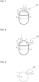
- Fig. 2 is a front view showing the refrigerant reservoir container 101 according to Embodiment 1.
- Fig. 3 is a top plan view showing the refrigerant reservoir container 101 according to Embodiment 1.
- Fig. 4 is a longitudinal cross-sectional view showing the refrigerant reservoir container 101 according to Embodiment 1.
- Fig. 5 is a cross-sectional view taken along the line A-A in Fig. 4 as viewed in the direction of arrows.
- the refrigerant reservoir container 101 As shown in Fig. 2 to Fig. 5 , the refrigerant reservoir container 101 according to Embodiment 1 is provided with a container body 1, an inflow pipe 2, an outflow pipe 3, and an undulation prevention plate 4.
- the container body 1 forms the outer contour of the refrigerant reservoir container 101.
- Two-phase gas-liquid refrigerant flowing out from the evaporator flows into the internal space of the container body 1 through the inflow pipe 2.
- the two-phase gas-liquid refrigerant includes refrigerating machine oil.
- the inflow pipe 2 is connected to the upper surface of the container body 1, and is provided for causing two-phase gas-liquid refrigerant flowing out from the evaporator to flow into an upper space 1a in the container body 1.
- the outflow pipe 3 is connected to the upper surface of the container body 1, and is provided for causing gas refrigerant and liquid refrigerant to flow out from the upper space 1a in the container body 1 to the outside of the container body 1.
- gas refrigerant separated from liquid refrigerant flows out from the upper space 1a in the container body 1 to the outside of the container body 1, and is sucked into the compressor 10.
- the undulation prevention plate 4 is located in the container body 1.
- the undulation prevention plate 4 partitions the internal space of the container body 1 into the upper space 1a and a lower space 1b and for causing liquid refrigerant separated from gas refrigerant to flow into the lower space 1b.
- the undulation prevention plate 4 reduces the likelihood of a situation in which liquid refrigerant 6 stored in the lower space 1b undulates about the gas-liquid interface, and droplets having scattered by the undulation of the liquid refrigerant 6 flows into the upper space 1a and then intrudes into the outflow pipe 3.
- the undulation prevention plate 4 is provided with a plurality of through holes 5 through which the upper space 1a and the lower space 1b communicate with each other and through which liquid refrigerant flows into the lower space 1b.
- the through holes 5 are annularly arranged along the inner wall surface of the container body 1.
- eight through holes 5 having the same shape and size are arranged at equal intervals.
- the through holes 5 have a circular shape, for example.
- the number of through holes 5 is not limited to eight shown in the drawing. Further, the shape of the through holes 5 is not limited to a circular shape shown in the drawing.
- the through holes 5 may have another shape, such as an elliptical shape and a rectangular shape, or may have a shape obtained by cutting away an arc shape from the outer edge of the undulation prevention plate 4.
- the undulation prevention plate 4 prevents scattering of the liquid refrigerant 6 stored in the lower space 1b by use of the center portion of the lower surface of the undulation prevention plate 4 surrounded by the through holes 5.
- two-phase gas-liquid refrigerant flows into the upper space 1a in the container body 1 through the inflow pipe 2. After the two-phase gas-liquid refrigerant flows into the upper space 1a, the two-phase gas-liquid refrigerant is separated into gas refrigerant and liquid refrigerant. Gas refrigerant with a low density accumulates in the upper space 1a in the container body 1, flows to the outside of the container body 1 through the outflow pipe 3, and is then sucked into the compressor 10.
- liquid refrigerant with a high density flows into the lower space 1b in the container body 1 through the plurality of through holes 5, which are provided to the undulation prevention plate 4, and is then stored in the lower space 1b in the container body 1. After a certain amount of the liquid refrigerant 6 flows into and is stored in the lower space 1b, the liquid refrigerant 6 is discharged to the compressor 10 through the through holes 5 and the outflow pipe 3.
- the refrigerant reservoir container 101 is provided with the container body 1 that forms the outer shell of the refrigerant reservoir container 101, the inflow pipe 2 connected to the container body 1 and through which two-phase gas-liquid refrigerant flows into the upper space 1a in the container body 1, the outflow pipe 3 connected to the container body 1 and through which gas refrigerant and liquid refrigerant flow from the upper space 1a in the container body 1 to the outside of the container body 1, and the undulation prevention plate 4 that is located in the container body 1 and partitions the internal space of the container body 1 into the upper space 1a and the lower space 1b.
- the undulation prevention plate 4 is provided with the plurality of through holes 5 through which the upper space 1a and the lower space 1b communicate with each other and through which liquid refrigerant flows into the lower space 1b.
- the through holes 5 are annularly arranged along the inner wall surface of the container body 1.
- liquid refrigerant separated from gas refrigerant in the upper space 1a is caused to pass through the plurality of through holes 5, annularly arranged along the inner wall surface of the container body 1, thus being efficiently stored in the lower space 1b.
- the undulation prevention plate 4 prevents the scattering by use of the center portion of the lower surface of the undulation prevention plate 4 and hence, it is possible to reduce the likelihood of a situation in which droplets of the undulating liquid refrigerant 6 reach the outflow pipe 3 and flows into the compressor 10 together with gas refrigerant. That is, the excessive outflow of the stored liquid refrigerant 6 is reduced and hence, dilution of refrigerating machine oil caused by inflow of liquid refrigerant into the compressor 10 is avoided, leading to achieving a high reliability of the compressor 10.
- Fig. 6 is a cross-sectional view showing a part of the refrigerant reservoir container 102 according to Embodiment 2.
- Components identical to the corresponding components in Embodiment 1 are given the same reference signs, and the description of such components will be omitted when appropriate.
- the refrigerant reservoir container 102 according to Embodiment 2 is also provided with the container body 1, the inflow pipe 2, the outflow pipe 3, and an undulation prevention plate 4 as shown in Fig. 2 to Fig. 4 .
- the undulation prevention plate 4 is provided with eight through holes (5a, 5b, 5c) through which the upper space 1a and the lower space 1b communicate with each other and through which liquid refrigerant flows into the lower space 1b.
- the eight through holes (5a, 5b, 5c) are annularly arranged along the inner wall surface of the container body 1.
- the refrigerant reservoir container 102 according to Embodiment 2 is characterized in that, of the plurality of through holes (5a, 5b, 5c), the through holes (5a, 5b) located closer to the inflow pipe 2 than are the through holes 5c each have a hole diameter larger than the hole diameter of each of the through holes 5c located closer to the outflow pipe 3 than are the through holes (5a, 5b).
- the through holes (5a, 5b, 5c) having different hole diameters are provided.
- one through hole 5a located closest to the inflow pipe 2 has the largest hole diameter.
- Two through holes 5b each adjacent to the through hole 5a each other each have an intermediate hole diameter.
- the area of the through hole 5a having the largest hole diameter is larger than the area of the through hole 5b having the intermediate hole diameter by approximately 20%, for example.
- the area of the through hole 5b having the intermediate hole diameter is larger than the area of the through hole 5c having the smallest hole diameter by approximately 20%, for example.
- the ratios of the sizes of the through holes (5a, 5b, 5c) are not limited to the above-mentioned ratios, and other ratios may be adopted.
- the configuration of the through holes (5a, 5b, 5c) of the refrigerant reservoir container 102 is not limited to the configuration shown in the drawing.
- the hole diameters of the through holes (5a, 5b, 5c) are not limited to three kinds shown in the drawing, and it is sufficient that two or more kinds of hole diameters be adopted. For example, a configuration may be adopted in which the through hole 5a having the largest hole diameter shown in Fig. 6 is combined with the through holes 5b having the intermediate hole diameter shown in Fig. 6 to provide an elongated hole.
- a configuration may be adopted in which all of a plurality of through holes have different hole diameters such that the hole diameters gradually increase toward the inflow pipe 2.
- a configuration may be adopted in which the center portion of the undulation prevention plate 4 is used as a boundary, and the total area of the through holes provided to the right half from the boundary is larger than the total area of the through holes provided to the left half from the boundary, the inflow pipe 2 is disposed above the right half, and the outflow pipe 3 is disposed above the left half.
- any configuration may be adopted provided that, of the plurality of through holes (5a, 5b, 5c), the through holes (5a, 5b) located closer to the inflow pipe 2 than are the through holes 5c each have a hole diameter larger than the hole diameter of each of the through holes 5c located closer to the outflow pipe 3 than are the through holes (5a, 5b).
- the through holes (5a, 5b) located closer to the inflow pipe 2 than are the through holes 5c each have the hole diameter larger than the hole diameter of each of the through holes 5c located closer to the outflow pipe 3 than are the through holes (5a, 5b).
- the undulation prevention plate 4 prevents the scattering by use of the center portion of the lower surface of the undulation prevention plate 4 and hence, it is possible to reduce the likelihood of a situation in which droplets of the undulating liquid refrigerant 6 reach the outflow pipe 3 and flow into the compressor 10 together with gas refrigerant.
- Fig. 7 is a longitudinal cross-sectional view showing the refrigerant reservoir container 103 according to Embodiment 3.
- Components identical to the corresponding components in Embodiment 1 are given the same reference signs, and the description of such components will be omitted when appropriate.
- the refrigerant reservoir container 103 is also provided with the undulation prevention plate 4 that is located in the container body 1, and partitions the internal space of the container body 1 into the upper space 1a and the lower space 1b.
- the undulation prevention plate 4 is provided with the plurality of through holes 5 through which the upper space 1a and the lower space 1b communicate with each other and through which liquid refrigerant flows into the lower space 1b.
- the plurality of through holes 5 are annularly arranged along the inner wall surface of the container body 1. The plurality of through holes 5 may be opened such that, as shown in Fig.
- the through holes (5a, 5b) located closer to the inflow pipe 2 than are the through holes 5c each have a hole diameter larger than the hole diameter of each of the through holes 5c located closer to the outflow pipe 3 than are the through holes (5a, 5b).
- the inflow pipe 2 is connected to the container body 1 such that the discharge port of the inflow pipe 2 faces toward the center position of the upper surface of the undulation prevention plate 4 while avoiding the through holes 5. It is not always necessary for the center position to be strictly the center of the upper surface of the undulation prevention plate 4, and the center position also includes positions slightly displaced from the center position.
- the inflow pipe 2 is connected to the container body 1 such that the discharge port of the inflow pipe 2 faces toward a position, on the upper surface of the undulation prevention plate 4, that avoids the through holes 5.
- the refrigerant reservoir container 103 causes the two-phase gas-liquid refrigerant to vigorously impinge on the upper surface of the undulation prevention plate 4. Accordingly, such impingement promotes separation between gas refrigerant and liquid refrigerant and hence, it is possible to efficiently store liquid refrigerant in the lower space 1b in the container body 1 through the through holes 5 of the undulation prevention plate 4.
- a refrigerant reservoir container 104 according to Embodiment 4 will be described with reference to Fig. 8 and Fig. 9.
- Fig. 8 is a longitudinal cross-sectional view showing the refrigerant reservoir container 104 according to Embodiment 4.
- Fig. 9 is a top plan view showing the refrigerant reservoir container 104 according to Embodiment 4.
- Components identical to the corresponding components in Embodiment 1 are given the same reference signs, and the description of such components will be omitted when appropriate.
- the refrigerant reservoir container 104 is also provided with the undulation prevention plate 4 that is located in the container body 1 and partitions the internal space of the container body 1 into the upper space 1a and the lower space 1b.
- the undulation prevention plate 4 is provided with the plurality of through holes 5 through which the upper space 1a and the lower space 1b communicate with each other and through which liquid refrigerant flows into the lower space 1b.
- the plurality of through holes 5 are annularly arranged along the inner wall surface of the container body 1. The plurality of through holes 5 may be opened such that, as shown in Fig.
- the through holes (5a, 5b) located closer to the inflow pipe 2 than are the through holes 5c each have a hole diameter larger than the hole diameter of each of the through holes 5c located closer to the outflow pipe 3 than are the through holes (5a, 5b).
- the inflow pipe 2 is connected to the container body 1 such that the discharge port of the inflow pipe 2 faces in the circumferential direction of the inner wall surface of the container body 1.
- the outflow pipe 3 is connected to the upper surface of the container body 1.
- the liquid refrigerant After the liquid refrigerant reaches the upper surface of the undulation prevention plate 4, the liquid refrigerant flows into the lower space 1b in the container body 1 through the plurality of through holes 5 and is stored in the lower space 1b in the container body 1.
- the gas refrigerant accumulates in the upper space 1a in the container body 1, flows to the outside of the container body 1 through the outflow pipe 3, and is then sucked into the compressor 10.
- the inflow pipe 2 is connected to the container body 1 such that the discharge port of the inflow pipe 2 faces in the circumferential direction of the inner wall surface of the container body 1.
- Fig. 10 is a longitudinal cross-sectional view showing the refrigerant reservoir container according to Embodiment 5.
- Fig. 11 is a cross-sectional view taken along the line B-B in Fig. 10 as viewed in the direction of arrows.
- Fig. 12 is a diagram schematically illustrating liquid refrigerant that flows into the refrigerant reservoir container according to Embodiment 5 through the inflow pipe, and then flows into the lower space through the through holes.
- Components identical to the corresponding components in Embodiment 1 are given the same reference signs, and the description of such components will be omitted when appropriate.
- the refrigerant reservoir container 105 is also provided with the undulation prevention plate 4 that is located in the container body 1 and partitions the internal space of the container body 1 into the upper space 1a and the lower space 1b.
- the undulation prevention plate 4 is provided with the plurality of through holes 5 through which the upper space 1a and the lower space 1b communicate with each other and through which liquid refrigerant flows into the lower space 1b.
- the plurality of through holes 5 are annularly arranged along the inner wall surface of the container body 1.
- the plurality of through holes have the same shape and size, and are arranged along the inner wall surface at equal intervals.
- the plurality of through holes 5 may be opened such that, as shown in Fig.
- the through holes (5a, 5b) located closer to the inflow pipe 2 than are the through holes 5c each have a hole diameter larger than the hole diameter of each of the through holes 5c located closer to the outflow pipe 3 than are the through holes (5a, 5b).
- the shape of the through holes 5 is not limited to a circular shape shown in the drawing.
- the through holes 5 may have a shape obtained by cutting away an arc shape from the outer edge portion of the undulation prevention plate 4.
- the undulation prevention plate 4 in Embodiment 5 has a liquid guide portion 4a that is inclined toward the lower space 1b and guides liquid refrigerant to the through holes 5.
- the through holes 5 are provided at the destination of liquid refrigerant guided by the liquid guide portion 4a.
- the undulation prevention plate 4 shown in Fig. 10 has a conical shape in which the center portion protrudes toward the upper surface of the container body 1.
- the liquid guide portion 4a is the inclined surface of a cone that is inclined toward the through holes 5 from the protruding center portion.
- Fig. 13 is a longitudinal cross-sectional view showing a modification of the refrigerant reservoir container according to Embodiment 5.
- An undulation prevention plate 4 shown in Fig. 13 is formed to have a liquid guide portion 4a inclined in one direction toward the lower space 1b.
- the liquid guide portion 4a is inclined such that the portion of the liquid guide portion 4a located under the inflow pipe 2 is inclined toward the lower space 1b.
- the through holes 5 are annularly provided along the inner wall surface of the container body 1.
- the refrigerant reservoir container 105 according to Embodiment 5 is not limited to the configurations shown in Fig. 10 to Fig. 13 .
- the refrigerant reservoir container 105 according to Embodiment 5 may adopt another configuration provided that the undulation prevention plate 4 has the liquid guide portion 4a inclined toward the lower space 1b and the through holes 5 are provided at the destination of refrigerant guided by the liquid guide portion 4a.
- the undulation prevention plate 4 of the refrigerant reservoir container 105 has the liquid guide portion 4a, which is inclined toward the lower space 1b and guides liquid refrigerant to the through holes 5.
- the undulation prevention plate 4 has a shape protruding toward the upper surface of the container body 1 and the inclined surface inclined toward the inner wall surface of the container body 1 from the protruding portion forms the liquid guide portion 4a.
- the refrigerant reservoir containers (101 to 105) and the refrigeration cycle apparatus 100 have been described above with reference to Embodiments. However, the refrigerant reservoir containers (101 to 105) and the refrigeration cycle apparatus 100 are not limited to the configurations of the above-mentioned Embodiments. For example, the refrigerant reservoir containers (101 to 105) are not limited to the configurations shown in the drawings, and may have other components. Further, the refrigeration cycle apparatus 100 is not limited to the configuration shown in the drawings, and may have other components. In short, the refrigerant reservoir containers (101 to 105) and the refrigeration cycle apparatus 100 have variations to which design changes or applications are normally added by those who are skilled in the art without departing from the technical concept.
- 1 container body, 1a: upper space, 1b: lower space, 2: inflow pipe, 3: outflow pipe, 4: undulation prevention plate, 4a: liquid guide portion, 5, 5a, 5b, 5c: through hole, 6: liquid refrigerant, 10: compressor, 11: flow switching device, 12: outdoor heat exchanger, 13: expansion mechanism, 14: indoor heat exchanger, 15: refrigerant pipe, 100: refrigeration cycle apparatus, 101, 102, 103, 104, 105: refrigerant reservoir container, 200: refrigerant circuit
Landscapes
- Engineering & Computer Science (AREA)
- Physics & Mathematics (AREA)
- Mechanical Engineering (AREA)
- Thermal Sciences (AREA)
- General Engineering & Computer Science (AREA)
- Chemical & Material Sciences (AREA)
- Analytical Chemistry (AREA)
- Power Engineering (AREA)
- Compressor (AREA)
Applications Claiming Priority (1)
| Application Number | Priority Date | Filing Date | Title |
|---|---|---|---|
| PCT/JP2021/018304 WO2022239211A1 (ja) | 2021-05-14 | 2021-05-14 | 冷媒貯留容器及び該冷媒貯留容器を備えた冷凍サイクル装置 |
Publications (2)
| Publication Number | Publication Date |
|---|---|
| EP4339536A1 true EP4339536A1 (de) | 2024-03-20 |
| EP4339536A4 EP4339536A4 (de) | 2024-05-29 |
Family
ID=84028989
Family Applications (1)
| Application Number | Title | Priority Date | Filing Date |
|---|---|---|---|
| EP21941943.9A Withdrawn EP4339536A4 (de) | 2021-05-14 | 2021-05-14 | Kältemittelaufbewahrungsbehälter und kältekreislaufvorrichtung mit diesem kältemittelaufbewahrungsbehälter |
Country Status (5)
| Country | Link |
|---|---|
| US (1) | US20240328689A1 (de) |
| EP (1) | EP4339536A4 (de) |
| JP (1) | JP7433522B2 (de) |
| CN (1) | CN117242310A (de) |
| WO (1) | WO2022239211A1 (de) |
Family Cites Families (13)
| Publication number | Priority date | Publication date | Assignee | Title |
|---|---|---|---|---|
| JP3104513B2 (ja) * | 1993-12-28 | 2000-10-30 | 三菱電機株式会社 | アキュムレータ |
| JP3215614B2 (ja) * | 1995-11-02 | 2001-10-09 | 松下精工株式会社 | 空気調和機の冷凍サイクルおよび冷凍サイクル部品 |
| JP4069567B2 (ja) | 1999-05-24 | 2008-04-02 | 株式会社デンソー | アキュムレータ |
| JP4897464B2 (ja) | 2006-12-15 | 2012-03-14 | サンデン株式会社 | 蒸気圧縮式冷凍サイクル |
| JP2008249242A (ja) | 2007-03-30 | 2008-10-16 | Showa Denko Kk | 冷凍サイクル用アキュムレータ |
| WO2012026496A1 (ja) | 2010-08-25 | 2012-03-01 | 三菱電機株式会社 | アキュムレータを付設する冷媒圧縮機及び蒸気圧縮式冷凍サイクル装置 |
| CN103604258B (zh) * | 2013-11-12 | 2015-08-12 | 上海交通大学 | 一种排液型气液分离器 |
| JP2015172469A (ja) | 2014-03-12 | 2015-10-01 | カルソニックカンセイ株式会社 | 気液分離器 |
| NL2013941B1 (nl) * | 2014-12-08 | 2016-10-11 | Flamco Bv | Afscheider en scheidwerkwijze. |
| JP2017125466A (ja) | 2016-01-15 | 2017-07-20 | ダイキン工業株式会社 | アキュムレータおよびそれを備える圧縮機 |
| CN207351006U (zh) * | 2017-08-25 | 2018-05-11 | 天津商业大学 | 一种卧式气液分离器 |
| CN109751798A (zh) * | 2017-11-02 | 2019-05-14 | 开利公司 | 气液分离器 |
| AU2020248049B2 (en) * | 2019-03-22 | 2023-06-01 | Nec Corporation | Liquid separator, cooling system, and gas-liquid separation method |
-
2021
- 2021-05-14 US US18/549,603 patent/US20240328689A1/en not_active Abandoned
- 2021-05-14 CN CN202180097762.6A patent/CN117242310A/zh active Pending
- 2021-05-14 EP EP21941943.9A patent/EP4339536A4/de not_active Withdrawn
- 2021-05-14 JP JP2023520703A patent/JP7433522B2/ja active Active
- 2021-05-14 WO PCT/JP2021/018304 patent/WO2022239211A1/ja not_active Ceased
Also Published As
| Publication number | Publication date |
|---|---|
| JPWO2022239211A1 (de) | 2022-11-17 |
| EP4339536A4 (de) | 2024-05-29 |
| JP7433522B2 (ja) | 2024-02-19 |
| WO2022239211A1 (ja) | 2022-11-17 |
| US20240328689A1 (en) | 2024-10-03 |
| CN117242310A (zh) | 2023-12-15 |
Similar Documents
| Publication | Publication Date | Title |
|---|---|---|
| US7131292B2 (en) | Gas-liquid separator | |
| JP4356214B2 (ja) | 油分離器および室外機 | |
| US11015850B2 (en) | Oil separator | |
| US5887444A (en) | Accumlator | |
| JP5940489B2 (ja) | 空気調和装置 | |
| CN110542251A (zh) | 一种改良的气液分离器 | |
| JP6827554B2 (ja) | 油分離器およびそれを備えた空気調和機 | |
| EP4339536A1 (de) | Kältemittelaufbewahrungsbehälter und kältekreislaufvorrichtung mit diesem kältemittelaufbewahrungsbehälter | |
| CN111928548A (zh) | 气液分离器、回油系统及空调系统 | |
| US11175078B2 (en) | Gas-liquid separator and air conditioner including the same | |
| JP7343611B2 (ja) | 気液分離装置および冷凍サイクル装置 | |
| JP4899641B2 (ja) | 混合流体分離装置 | |
| JPH08178476A (ja) | 圧縮機用アキュームレータ | |
| EP4379291A1 (de) | Kältemittelaufbewahrungsbehälter und kältekreislaufvorrichtung mit diesem kältemittelaufbewahrungsbehälter | |
| EP4386281A1 (de) | Kältemittelaufbewahrungsbehälter und kältekreislaufvorrichtung mit diesem kältemittelaufbewahrungsbehälter | |
| WO2021229649A1 (ja) | アキュムレータおよび冷凍サイクル装置 | |
| EP4425074A1 (de) | Kältemittelaufbewahrungsbehälter und kältekreislaufvorrichtung mit diesem kältemittelaufbewahrungsbehälter | |
| WO2023166705A1 (ja) | 冷媒貯留容器及び該冷媒貯留容器を備えた冷凍サイクル装置 | |
| US20250116442A1 (en) | Condenser vessel, system, and method for separating oil from an oil-refrigerant mixture | |
| WO2024029028A1 (ja) | 油分離器および冷凍サイクル装置 | |
| CN211041492U (zh) | 一种气液分离闪发器及其空调器系统 | |
| WO2025062532A1 (ja) | 冷凍サイクル装置 | |
| WO2023238234A1 (ja) | 熱交換器 | |
| KR20000055694A (ko) | 에어컨용 오일 분리 장치 | |
| JP2010276250A (ja) | 空気調和機 |
Legal Events
| Date | Code | Title | Description |
|---|---|---|---|
| STAA | Information on the status of an ep patent application or granted ep patent |
Free format text: STATUS: THE INTERNATIONAL PUBLICATION HAS BEEN MADE |
|
| PUAI | Public reference made under article 153(3) epc to a published international application that has entered the european phase |
Free format text: ORIGINAL CODE: 0009012 |
|
| STAA | Information on the status of an ep patent application or granted ep patent |
Free format text: STATUS: REQUEST FOR EXAMINATION WAS MADE |
|
| 17P | Request for examination filed |
Effective date: 20231109 |
|
| AK | Designated contracting states |
Kind code of ref document: A1 Designated state(s): AL AT BE BG CH CY CZ DE DK EE ES FI FR GB GR HR HU IE IS IT LI LT LU LV MC MK MT NL NO PL PT RO RS SE SI SK SM TR |
|
| A4 | Supplementary search report drawn up and despatched |
Effective date: 20240429 |
|
| RIC1 | Information provided on ipc code assigned before grant |
Ipc: F25B 43/00 20060101AFI20240423BHEP |
|
| DAV | Request for validation of the european patent (deleted) | ||
| DAX | Request for extension of the european patent (deleted) | ||
| STAA | Information on the status of an ep patent application or granted ep patent |
Free format text: STATUS: THE APPLICATION HAS BEEN WITHDRAWN |
|
| 18W | Application withdrawn |
Effective date: 20240828 |