EP4339714B1 - Montre adaptée à génerer une animation séquentielle - Google Patents
Montre adaptée à génerer une animation séquentielle Download PDFInfo
- Publication number
- EP4339714B1 EP4339714B1 EP22196422.4A EP22196422A EP4339714B1 EP 4339714 B1 EP4339714 B1 EP 4339714B1 EP 22196422 A EP22196422 A EP 22196422A EP 4339714 B1 EP4339714 B1 EP 4339714B1
- Authority
- EP
- European Patent Office
- Prior art keywords
- watch
- disc
- pattern
- graphical representation
- crystal
- Prior art date
- Legal status (The legal status is an assumption and is not a legal conclusion. Google has not performed a legal analysis and makes no representation as to the accuracy of the status listed.)
- Active
Links
Images


Classifications
-
- G—PHYSICS
- G04—HOROLOGY
- G04B—MECHANICALLY-DRIVEN CLOCKS OR WATCHES; MECHANICAL PARTS OF CLOCKS OR WATCHES IN GENERAL; TIME PIECES USING THE POSITION OF THE SUN, MOON OR STARS
- G04B45/00—Time pieces of which the indicating means or cases provoke special effects, e.g. aesthetic effects
- G04B45/0023—Inscriptions or pictures moved by the clockwork, e.g. for advertising
-
- G—PHYSICS
- G04—HOROLOGY
- G04B—MECHANICALLY-DRIVEN CLOCKS OR WATCHES; MECHANICAL PARTS OF CLOCKS OR WATCHES IN GENERAL; TIME PIECES USING THE POSITION OF THE SUN, MOON OR STARS
- G04B45/00—Time pieces of which the indicating means or cases provoke special effects, e.g. aesthetic effects
- G04B45/0007—Light-, colour-, line-, or spot-effects caused by parts or pictures moved by the clockwork
-
- G—PHYSICS
- G04—HOROLOGY
- G04B—MECHANICALLY-DRIVEN CLOCKS OR WATCHES; MECHANICAL PARTS OF CLOCKS OR WATCHES IN GENERAL; TIME PIECES USING THE POSITION OF THE SUN, MOON OR STARS
- G04B45/00—Time pieces of which the indicating means or cases provoke special effects, e.g. aesthetic effects
- G04B45/0038—Figures or parts thereof moved by the clockwork
-
- G—PHYSICS
- G04—HOROLOGY
- G04B—MECHANICALLY-DRIVEN CLOCKS OR WATCHES; MECHANICAL PARTS OF CLOCKS OR WATCHES IN GENERAL; TIME PIECES USING THE POSITION OF THE SUN, MOON OR STARS
- G04B45/00—Time pieces of which the indicating means or cases provoke special effects, e.g. aesthetic effects
- G04B45/02—Time pieces of which the clockwork is visible partly or wholly
-
- G—PHYSICS
- G04—HOROLOGY
- G04B—MECHANICALLY-DRIVEN CLOCKS OR WATCHES; MECHANICAL PARTS OF CLOCKS OR WATCHES IN GENERAL; TIME PIECES USING THE POSITION OF THE SUN, MOON OR STARS
- G04B19/00—Indicating the time by visual means
- G04B19/20—Indicating by numbered bands, drums, discs, or sheets
- G04B19/202—Indicating by numbered bands, drums, discs, or sheets by means of turning discs
Definitions
- the invention relates to the field of watchmaking, and in particular to watch complications.
- the invention relates to a watch adapted to generate a sequential animation.
- Animations are part of the answers provided in response to this need. In addition, they often contribute to the notoriety of a watch. These animations are for example formed by watch complications, such as a tourbillon, a moon phase, a chronograph, etc. or by an oscillating weight.
- the document EP 3 839 647 A1 shows a moiré effect winding assembly for an automatic timepiece movement.
- the present invention falls within this problem of providing a user with a watch whose visual appearance is unique and particularly attractive.
- the invention relates to a watch comprising a case comprising a middle part to which a crystal and a transparent back are fixed so as to form an internal volume.
- Said watch comprises a watch movement housed in the internal volume of the case, comprising a structure carrier through which extends a shaft adapted to be rotated by said watch movement and carrying, at one of its ends opening beyond said carrier structure, opposite the glass, an indicator of a time value, and at the other end opening beyond said carrier structure, opposite the back, a disc on which extends a pattern opposite a graphic representation.
- the pattern and the graphic representation are shaped so that, when the shaft rotates, they cooperate with each other in order to generate a sequential animation by moiré effect formed by a sequence of at least two distinct images.
- an animation is generated by taking advantage of the energy provided by the watch movement.
- the rotation of the disc makes it possible to generate an animation whose speed is relatively high.
- the invention advantageously makes it possible, in particular, to generate an animation from an existing conventional watch movement, without requiring significant modifications to the latter.
- the invention may further comprise one or more of the following features, taken individually or in any technically possible combination.
- the graphic representation is formed on a background glass.
- the pattern and the graphic representation are shaped such that, upon rotation of the shaft, they cooperate with each other to generate a sequential animation formed by a sequence of four distinct images.
- the indicator of a time value is a second hand, the shaft being rotated so as to complete one revolution in one minute.
- the pattern and graphic representation are shaped such that between two successive generated images, the disk rotates six degrees.
- the base is formed by a fixing ring onto which a crystal is driven, the graphic representation extending over one face of said crystal.
- the fixing ring is screwed against the caseband by a plurality of screws distributed around its periphery, each engaged in a tapped hole extending into the caseband.
- the graphic representation is produced by depositing a thin layer on a face of the bottom arranged opposite the watch movement and forming a set of opaque zones.
- the pattern is formed by a plurality of identical spirals extending from the center of the disc to its periphery, and being distributed regularly around the center of the disc, said pattern being produced by the deposition of a thin layer on one face of the disc arranged opposite the bottom.
- the disc and the ice are separated by a distance of less than 0.5 mm.
- the disc advantageously has a diameter of approximately 10 mm.
- the pattern and graphical representation are configured such that the sequential animation involves moving an element in a rectilinear direction.
- the invention relates to a watch 10 adapted to generate a sequential animation, in particular visible through a transparent background 14.
- the watch 10 comprises a case 11 comprising a caseband 12 to which a crystal 13 and the transparent back 14 are fixed.
- the caseband 12, the crystal 13 and the back 14 form an internal volume in which is housed a watch movement 15 shown schematically on the Figure 1 .
- the bottom 14 is formed, in particular in the preferred embodiment of the invention, by a fixing ring 140 onto which a crystal 141 is driven, as shown in Figure 1 .
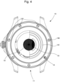
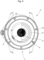
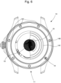
- this fixing ring 140 is screwed against the caseband 12 by a plurality of screws 120 distributed around its periphery, each of the screws 120 being engaged in a tapped hole extending into the caseband 12. This characteristic, visible on the figures 4 to 7 , allows the bottom 14 to be fixed to the middle 12 according to a very precise relative angular position.
- the watch movement 15 comprises a supporting structure through which extends a shaft 16 kinematically connected to a driving member of the watch movement 15 so as to be driven in rotation.
- the supporting structure is known per se to those skilled in the art and consists of bridges and/or a plate.
- the driving member of the watch movement 15 is known per se to those skilled in the art and may be formed by a barrel spring, an electric motor, etc.
- the shaft 16 extends between two ends, one of which, called the “upper end”, opens beyond said supporting structure, opposite the glass 13, and the other of which, called the “lower end”, opens beyond said supporting structure, opposite the bottom 14.
- the shaft 16 carries, at its upper end, an indicator of a time value 17, preferably formed by a second hand, as shown in the Figure 1 in an exemplary embodiment of the invention, and at its lower end, a disc 18.
- the time value indicator 17 and the disc 18 may each be attached to the shaft 16 by means of a barrel, as illustrated in FIG. Figure 1 .
- the shaft 16 is therefore preferably driven in rotation so as to complete a complete revolution in one minute.
- the shaft 16 is therefore driven in a rotation of six degrees every second.
- the disc 18 comprises a body 180 on which an opaque pattern 181 extends, preferably on a face arranged opposite the base 14.
- the pattern 181 has, in the exemplary embodiment shown in the figures 2 And 4 to 7 , an overall shape of several spirals all starting from the same central point of the disc 18 and extending from said center to the periphery of the disc 18. Said spirals are identical to each other and each represents a portion of an Archimedean spiral. These spirals are distributed regularly around the center of the disc 18, preferably extend over an angle of twenty-four degrees and are preferably separated from each other by an angle of six degrees.
- each spiral is defined between two curves conforming to Archimedean spirals, said curves delimiting the contours of said spiral, the distance between said curves is representative of a rotation of the disc 18 over an angle of twenty-four degrees.
- the distance between these two curves is representative of a rotation of the disk 18 through an angle of six degrees.
- the pattern 181 is produced by depositing a thin layer, for example metallic.
- the body 180 of the disc 18 can be made of a transparent material, for example glass or sapphire, or opaque, such as a metal or a polymer.
- the bottom 14 comprises, on one face of the glass 141 opposite the watch movement 15, a graphic representation 142 as shown in the Figure 3 in an exemplary embodiment of the invention.
- the graphic representation 142 is formed by a set of opaque zones contrasting with the transparency of the rest of the glass 141 of the bottom 14.
- the graphic representation 142 is produced by a deposit of a thin layer, for example metallic.
- the pattern 181 and the graphic representation 142 can be produced by screen printing, decalcomania, surface treatment, painting, enameling, etc.
- the graphic representation 142 and the pattern 181 are arranged to be opposite each other. More precisely, they are arranged so that the pattern 181 is opposite at least a part of the graphic representation 142. Furthermore, the graphic representation 142, and in particular the opaque areas, has a shape such that its alignment with the disc 18 generates an image, depending on the angular position of said disc 18, as visible on the figures 4 to 7 .
- the image is generated by cooperation between the graphic representation 142 and the pattern 181.
- the pattern 181 and the graphic representation 142 are shaped so that, during the rotation of the shaft 16, they cooperate with each other in order to generate a sequential animation by moiré effect formed by a sequence of at least two distinct images appearing through the background 14, a new image being generated with each successive rotation of the disc 18.
- the rotation of the shaft 16 thus makes it possible to generate a visual effect of homogeneous fading of the colors of the pattern 181 and of the body of the disc 18.
- the rotation of the shaft 16, and therefore of the disc 18, makes it possible to generate a sequential animation by moiré effect formed by four successive images, as visible in the figures 4 to 7
- This sequential animation consists, in the preferred embodiment of the invention, of moving an element 19, in this case a character, in a rectilinear direction, as successively shown in the aforementioned figures.
- the disc 18 can be arranged at a very short distance from the bottom 14, and from the crystal 141 in particular, so that a user cannot distinguish any offset between the pattern 181 and the graphic representation 142.
- the distance separating the disc 18 and the crystal 141 is of the order of a few tenths of a millimeter, preferably less than 0.5 mm, for example 0.2 mm.
- the disc 18 must have dimensions large enough for the pattern 181 to be easily visible, while being narrow enough to limit inertia and the risk of imbalance.
- the disc 18 advantageously has a diameter of several millimeters, for example, approximately 10 mm.
- the watch 10 comprises, on a first face, the display of at least one watch function, such as the display of the current time, and on a second face, the sequential animation.
- the animation is intended to be active, continuously, under the drive of the clock movement 15.
- the invention is advantageously suitable for any existing watch movement for the creation of sequential animations, with a reasonable cost. Furthermore, it may possibly generate an increase in the thickness of the watch case 11, but this is negligible insofar as the additional thickness is limited to the thickness of the disc 18 and the safety clearances between said disc 18 and the watch movement 15 on the one hand, and the glass 141 of the back 14 on the other hand.
- the graphic representation 142 may be formed on a structural element of the watch movement 15, for example on a bridge or a plate of the latter, instead of being formed on the crystal 141 of the back 14.
- the graphic representation 142 may be arranged on one side or the other of the pattern 181.
- the invention can be implemented both for watches comprising mechanical watch movements and for watches comprising electric or electromechanical watch movements.
Landscapes
- Physics & Mathematics (AREA)
- General Physics & Mathematics (AREA)
- Electromechanical Clocks (AREA)
- Electric Clocks (AREA)
- Displays For Variable Information Using Movable Means (AREA)
- Adornments (AREA)
Description
- L'invention relève du domaine de l'horlogerie, et notamment des complications horlogères.
- Plus particulièrement, l'invention concerne une montre adaptée à générer une animation séquentielle.
- Afin de se démarquer de la concurrence et de proposer des produits attractifs, les maisons horlogères apportent un soin particulier à l'aspect esthétique des montres. A cet effet, la décoration des éléments d'habillage d'une montre, dont le cadran, la lunette et les afficheurs, et les éventuelles complications horlogères font souvent l'objet d'important développements et d'efforts de conception.
- Les animations font partie des réponses apportées en réponse à ce besoin En outre, elles participent souvent à la notoriété d'une montre. Ces animations sont par exemple formées par des complications horlogères, telles qu'un tourbillon, une phase de lune, un chronographe, etc. ou par une masse oscillante. Le document
EP 3 839 647 A1 montre un ensemble de remontage à effet moiré pour mouvement automatique de pièce d'horlogerie. - La présente invention s'inscrit dans cette problématique consistant à fournir à un utilisateur une montre dont l'aspect visuel est unique et particulièrement attrayant.
- À cet effet, l'invention concerne une montre comprenant une boite comportant une carrure à laquelle sont fixés une glace et un fond transparent de sorte à former un volume interne. Ladite montre comprend un mouvement horloger logé dans le volume interne de la boite, comportant une structure porteuse à travers laquelle s'étend un arbre adapté à être entraîné en rotation par ledit mouvement horloger et portant, à l'une de ses extrémités débouchant au-delà de ladite structure porteuse, en vis-à-vis de la glace, un indicateur d'une valeur temporelle, et à l'autre extrémité débouchant au-delà de ladite structure porteuse, en vis-à-vis du fond, un disque sur lequel s'étend un motif en regard d'une représentation graphique. Le motif et la représentation graphique sont conformés de sorte que, lors de la rotation de l'arbre, ils coopèrent l'un avec l'autre afin de générer une animation séquentielle par effet de moiré formée par une séquence d'au moins deux images distinctes.
- Grâce aux caractéristiques de l'invention, une animation est générée en tirant partie de l'énergie fournie par le mouvement horloger. En particulier, la rotation du disque permet de générer une animation dont la vitesse est relativement importante.
- En outre, l'invention permet avantageusement notamment, de pouvoir générer une animation à partir d'un mouvement horloger conventionnel, existant, sans nécessiter d'importantes modifications de ce dernier.
- Dans des modes particuliers de réalisation, l'invention peut comporter en outre l'une ou plusieurs des caractéristiques suivantes, prises isolément ou selon toutes les combinaisons techniquement possibles.
- Dans des modes particuliers de réalisation, la représentation graphique est formée sur une glace du fond.
- Dans des modes particuliers de réalisation, le motif et la représentation graphique sont conformés de sorte que, lors de la rotation de l'arbre, ils coopèrent l'un avec l'autre afin de générer une animation séquentielle formée par une séquence de quatre images distinctes.
- Dans des modes particuliers de réalisation, l'indicateur d'une valeur temporelle est une aiguille des secondes, l'arbre étant entraîné en rotation de sorte à réaliser un tour complet en une minute.
- Dans des modes particuliers de réalisation, le motif et la représentation graphique sont conformées de sorte qu'entre deux images successives générées, le disque pivote de six degrés.
- Dans des modes particuliers de réalisation, le fond est formé par une bague de fixation sur laquelle est chassée une glace, la représentation graphique s'étendant sur une face de ladite glace.
- Dans des modes particuliers de réalisation, la bague de fixation est vissée contre la carrure par une pluralité de vis réparties sur sa périphérie, chacune engagée dans un trou taraudé s'étendant dans la carrure.
- Dans des modes particuliers de réalisation, la représentation graphique est réalisée par le dépôt d'une couche mince sur une face du fond agencée en vis-à-vis du mouvement horloger et formant un ensemble de zones opaques.
- Dans des modes particuliers de réalisation, le motif est formé par une pluralité de spirales identiques s'étendant depuis le centre du disque jusqu'à sa périphérie, et étant réparties régulièrement autour du centre du disque, ledit motif étant réalisé par le dépôt d'une couche mince sur une face du disque agencée en regard du fond.
- Dans des modes particuliers de réalisation, le disque et la glace sont séparés par une distance inférieure à 0,5 mm.
- Dans des modes particuliers de réalisation, le disque présente avantageusement un diamètre d'environ 10 mm.
- Dans des modes particuliers de réalisation, le motif et la représentation graphique sont conformés de sorte que l'animation séquentielle consiste à déplacer un élément suivant une direction rectiligne.
- D'autres caractéristiques et avantages de l'invention apparaîtront à la lecture de la description détaillée suivante donnée à titre d'exemple nullement limitatif, en référence aux dessins annexés dans lesquels :
- la
figure 1 représente schématiquement une vue en coupe partielle d'une montre selon un exemple préféré de réalisation de l'invention ; - la
figure 2 représente une vue de dessus d'un disque de la montre de lafigure 1 ; - la
figure 3 représente une vue de dessus d'une glace de la montre de lafigure 1 ; - les
figures 4 à 7 représentent une vue de dessous de la montre de lafigure 1 , dans lesquelles le disque occupe des positions angulaires successives différentes de sorte à générer des images distinctes formant une animation séquentielle. - On note que les figures ne sont pas nécessairement dessinées à l'échelle pour des raisons de clarté.
- L'invention concerne une montre 10 adaptée à générer une animation séquentielle, en particulier visible à travers un fond 14 transparent.
- Comme illustré sur la vue en coupe de la
figure 1 , la montre 10 comporte une boite 11 comprenant une carrure 12 à laquelle sont fixés une glace 13 et le fond 14 transparent. La carrure 12, la glace 13 et le fond 14 forment un volume interne dans lequel est logé un mouvement horloger 15 représenté schématiquement sur lafigure 1 . - Le fond 14 est formé, en particulier dans l'exemple préféré de réalisation de l'invention, par une bague de fixation 140 sur laquelle est chassée une glace 141, comme le montre la
figure 1 . Préférentiellement, cette bague de fixation 140 est vissée contre la carrure 12 par une pluralité de vis 120 réparties sur sa périphérie, chacune des vis 120 étant engagée dans un trou taraudé s'étendant dans la carrure 12. Cette caractéristique, visible sur lesfigures 4 à 7 , permet de fixer le fond 14 à la carrure 12 selon une position angulaire relative très précise. - Le mouvement horloger 15 comporte une structure porteuse à travers laquelle s'étend un arbre 16 lié cinématiquement à un organe moteur du mouvement horloger 15 de sorte à être entraîné en rotation. La structure porteuse est connue en soi par l'homme du métier et est constituée de ponts et/ou d'une platine. De la même manière, l'organe moteur du mouvement horloger 15 est connu en soi par l'homme du métier et peut être formé par un ressort de barillet, un moteur électrique, etc.
- L'arbre 16 s'étend entre deux extrémité dont une, dite « extrémité supérieure », débouche au-delà de ladite structure porteuse, en vis-à-vis de la glace 13, et dont l'autre, dite « extrémité inférieure », débouche au-delà de ladite structure porteuse, en vis-à-vis du fond 14.
- Les termes « supérieur » et « inférieur » sont relatifs à la disposition de la montre 10 sur la
figure 1 et sont choisis afin de simplifier la compréhension de l'invention. - L'arbre 16 porte, à son extrémité supérieure, un indicateur d'une valeur temporelle 17, préférentiellement formé par une aiguille des secondes, comme le montre la
figure 1 dans un exemple de réalisation de l'invention, et à son extrémité inférieure, un disque 18. - L'indicateur d'une valeur temporelle 17 et le disque 18 peuvent être chacun fixés à l'arbre 16 par l'intermédiaire d'un canon, tel qu'illustré sur la
figure 1 . - L'arbre 16 est donc préférentiellement entraîné en rotation de sorte à réaliser un tour complet en une minute. L'arbre 16 est donc entraîné dans une rotation de six degrés chaque seconde.
- Le disque 18 comporte un corps 180 sur lequel s'étend un motif 181 opaque, préférentiellement sur une face agencée en vis-à-vis du fond 14. Le motif 181 présente, dans l'exemple de réalisation représenté sur les
figures 2 et4 à 7 , une forme globale de plusieurs spirales partant toutes d'un même point central du disque 18 et s'étendant depuis ledit centre jusqu'à la périphérie du disque 18. Lesdites spirales sont identiques les unes des autres et représentent chacune une portion d'une spirale d'Archimède. Ces spirales sont réparties régulièrement autour du centre du disque 18, s'étendent préférentiellement sur un angle de vingt-quatre degrés et sont préférentiellement séparées les unes des autres par un angle de six degrés. Autrement dit, si l'on considère que chaque spirale est définie entre deux courbes conformes à des spirales d'Archimède, lesdites courbes délimitant les contours de ladite spirale, la distance entre lesdites courbes est représentative d'une rotation du disque 18 sur un angle de vingt-quatre degrés. De manière analogue, si l'on considère que deux spirales adjacentes sont séparées par deux courbes conformes à des spirales d'Archimède, la distance entre ces deux courbes est représentative d'une rotation du disque 18 sur un angle de six degrés. - Préférentiellement, le motif 181 est réalisé par un dépôt de couche mince, par exemple métallique. Le corps 180 du disque 18 peut être réalisé dans un matériau transparent, par exemple du verre ou du saphir, ou opaque, tel qu'un métal ou un polymère.
- Préférentiellement, le fond 14 comporte, sur une face de la glace 141 en vis-à-vis du mouvement horloger 15, une représentation graphique 142 telle que représentée sur la
figure 3 dans un exemple de réalisation de l'invention. - En particulier, la représentation graphique 142 est formée par un ensemble de zones opaques contrastant avec la transparence du reste de la glace 141 du fond 14. Préférentiellement, la représentation graphique 142 est réalisée par un dépôt de couche mince, par exemple métallique.
- Le motif 181 et la représentation graphique 142 peuvent être réalisés par sérigraphie, décalcomanie, traitement de surface, peinture, émaillage, etc.
- La représentation graphique 142 et le motif 181 sont agencés pour être en vis-à-vis. Plus précisément, ils sont agencés de sorte que le motif 181 soit en vis-à-vis d'au moins une partie de la représentation graphique 142. En outre, la représentation graphique 142, et en particulier les zones opaques, présente une forme telle que son alignement avec le disque 18 génère une image, suivant la position angulaire dudit disque 18, comme visible sur le
figures 4 à 7 . - En particulier, du fait de la transparence de la glace 141 du fond 14, toute ou partie de certaines zones opaques sont visibles lorsqu'elles s'étendent en vis-à-vis des espaces séparant deux spirales adjacentes du motif 181. Le reste des zones opaques et/ou des parties de zones opaques est alors agencé en regard des spirales, et est donc dissimulé.
- En synthèse, l'image est générée par une coopération entre la représentation graphique 142 et le motif 181. On comprend alors l'importance de la maitrise de la position angulaire du fond 14 vis-à-vis de la carrure 12 afin que l'image générée par la coopération entre le motif 181 et la représentation graphique 142 soit exempt de défauts, par exemple dus à un mauvais alignement entre ledit motif 181 et ladite représentation graphique 142.
- En particulier, le motif 181 et la représentation graphique 142 sont conformés de sorte que, lors de la rotation de l'arbre 16, ils coopèrent l'un avec l'autre afin de générer une animation séquentielle par effet de moiré formée par une séquence d'au moins deux images distinctes apparaissant à travers le fond 14, une nouvelle image étant générée à chaque rotation successive du disque 18. La rotation de l'arbre 16 permet ainsi de générer un effet visuel de fondu homogène des couleurs du motif 181 et du corps du disque 18.
- Sur les exemples de réalisation représentés sur les figures, la rotation de l'arbre 16, et donc du disque 18, permet de générer une animation séquentielle par effet de moiré formée par quatre images successives, tel que visible sur les
figures 4 à 7 . Cette animation séquentielle consiste, dans l'exemple préféré de réalisation de l'invention, à déplacer un élément 19, en l'occurrence un personnage, suivant une direction rectiligne, comme le montrent successivement les figures précitées. - En prenant en considération les dimensions des spirales du motif 181 mentionnées ci-dessus, le disque 18 étant entraîné de sorte à pivoter de six degrés toutes les secondes, quinze animations sont générées en une minute, ce qui permet d'obtenir une succession d'animations relativement dynamiques et attrayantes lors de la rotation de l'arbre 16.
- Le choix des dimensions et des formes du motif 181 et de la représentation graphique 142, ainsi que du nombre d'animation par minute, permet avantageusement d'obtenir une animation claire et très facilement lisible, et de nécessiter des tolérances de fabrication et d'alignement suffisamment larges.
- A titre d'exemple, le disque 18 peut être agencé à une très faible distance du fond 14, et de la glace 141 en particulier, de sorte qu'un utilisateur ne puisse pas distinguer de décalage entre le motif 181 et la représentation graphique 142. Préférentiellement, la distance séparant le disque 18 et la glace 141 est de l'ordre de quelques dixièmes de millimètres, préférentiellement inférieure à 0,5 mm, par exemple 0,2 mm.
- Par ailleurs, le disque 18 doit présenter des dimensions suffisamment importantes pour que le motif 181 puisse être facilement visible, tout en étant suffisamment étroit pour limiter l'inertie et les risques de balourd. A cet effet, le disque 18 présente avantageusement un diamètre de plusieurs millimètres, par exemple, environ 10 mm.
- Pour résumer, la montre 10 comporte, sur une première face, l'affichage d'au moins une fonction horlogère, tel que l'affichage de l'heure courante, et sur une deuxième face, l'animation séquentielle.
- Dans l'exemple de réalisation décrit ci-avant, l'animation est destinée à être active, en continu, sous l'entraînement du mouvement horloger 15.
- Toutefois, il est envisageable de conditionner l'activation de l'animation à la commande d'une fonction horlogère, ou à la sollicitation d'un organe de commande dédié.
- L'invention est avantageusement apte à convenir à tout mouvement horloger existant pour la création d'animations séquentielles, avec un coût raisonnable. Par ailleurs, elle peut éventuellement générer une augmentation de l'épaisseur de la boite 11 de montre, mais celle-ci est négligeable dans la mesure où l'épaisseur supplémentaire se limite à l'épaisseur du disque 18 et aux jeux de sécurité entre ledit disque 18 et le mouvement horloger 15 d'une part, et la glace 141 du fond 14 d'autre part.
- De manière plus générale, il est à noter que les modes de mise en œuvre et de réalisation considérés ci-dessus ont été décrits à titre d'exemples non limitatifs, et que d'autres variantes sont par conséquent envisageables.
- Notamment, dans des exemples de réalisation de l'invention non représenté sur les figures, la représentation graphique 142 peut être formée sur un élément de structure du mouvement horloger 15, par exemple sur un pont ou une platine de ce dernier, au lieu d'être formée sur la glace 141 du fond 14. En d'autres termes, la représentation graphique 142 peut être agencée d'un côté ou de l'autre du motif 181.
- Par ailleurs, l'invention peut être mise en œuvre aussi bien pour des montres comprenant des mouvements horlogers mécaniques que pour des montres comprenant des mouvements horlogers électriques ou électromécaniques.
Claims (12)
- Montre (10) comprenant une boite (11) comportant une carrure (12) à laquelle sont fixés une glace (13) et un fond (14) transparent de sorte à former un volume interne, ladite montre (10) comprenant un mouvement horloger (15) logé dans le volume interne de la boite (11), comportant une structure porteuse à travers laquelle s'étend un arbre (16) adapté à être entraîné en rotation par ledit mouvement horloger (15) et portant, à l'une de ses extrémités débouchant au-delà de ladite structure porteuse, en vis-à-vis de la glace (13), un indicateur d'une valeur temporelle (17), la montre étant caractérisée en ce que l'arbre (16) porte, à son autre extrémité débouchant au-delà de ladite structure porteuse, en vis-à-vis du fond (14), un disque (18) sur lequel s'étend un motif (181) en regard d'une représentation graphique (142), le motif (181) et la représentation graphique (142) étant conformés de sorte que, lors de la rotation de l'arbre (16), ils coopèrent l'un avec l'autre afin de générer une animation séquentielle par effet de moiré formée par une séquence d'au moins deux images distinctes.
- Montre (10) selon la revendication 1, dans laquelle la représentation graphique (142) est formée sur une glace (141) du fond (14).
- Montre (10) selon l'une des revendications 1 ou 2, dans laquelle le motif (181) et la représentation graphique (142) sont conformés de sorte que, lors de la rotation de l'arbre (16), ils coopèrent l'un avec l'autre afin de générer une animation séquentielle formée par une séquence de quatre images distinctes.
- Montre (10) selon la revendication 1 à 3, dans laquelle l'indicateur d'une valeur temporelle (17) est une aiguille des secondes, l'arbre (16) étant entraîné en rotation de sorte à réaliser un tour complet en une minute.
- Montre (10) selon la revendication 4, dans laquelle le motif (181) et la représentation graphique (142) sont conformées de sorte qu'entre deux images successives générées, le disque (18) pivote de six degrés.
- Montre (10) selon l'une des revendications 1 à 5, dans laquelle le fond (14) est formé par une bague de fixation (140) sur laquelle est chassée une glace (141), la représentation graphique (142) s'étendant sur une face de ladite glace (141).
- Montre (10) selon la revendication 6, dans laquelle la bague de fixation (140) est vissée contre la carrure (12) par une pluralité de vis (120) réparties sur sa périphérie, chacune engagée dans un trou taraudé s'étendant dans la carrure (12).
- Montre (10) selon l'une des revendications 1 à 7, dans laquelle la représentation graphique (142) est réalisée par le dépôt d'une couche mince sur une face du fond (14) agencée en vis-à-vis du mouvement horloger (15) et formant un ensemble de zones opaques.
- Montre (10) selon l'une des revendications 1 à 8, dans laquelle le motif (181) est formé par une pluralité de spirales identiques s'étendant depuis le centre du disque (18) jusqu'à sa périphérie, et étant réparties régulièrement autour du centre du disque (18), ledit motif (181) étant réalisé par le dépôt d'une couche mince sur une face du disque (18) agencée en regard du fond (14).
- Montre (10) selon l'une des revendications 1 à 9, dans laquelle le disque (18) et la glace (141) sont séparés par une distance inférieure à 0,5 mm.
- Montre (10) selon l'une des revendications 1 à 10, dans laquelle le disque (18) présente avantageusement un diamètre d'environ 10 mm.
- Montre (10) selon l'une des revendications 1 à 11, dans laquelle le motif (181) et la représentation graphique (142) sont conformés de sorte que l'animation séquentielle consiste à déplacer un élément (19) suivant une direction rectiligne.
Priority Applications (4)
| Application Number | Priority Date | Filing Date | Title |
|---|---|---|---|
| EP22196422.4A EP4339714B1 (fr) | 2022-09-19 | 2022-09-19 | Montre adaptée à génerer une animation séquentielle |
| US18/348,018 US20240094678A1 (en) | 2022-09-19 | 2023-07-06 | Watch adapted to generate a sequential animation |
| JP2023125292A JP7644798B2 (ja) | 2022-09-19 | 2023-08-01 | 連続アニメーションの生成に適合する時計 |
| CN202311212400.4A CN117724319A (zh) | 2022-09-19 | 2023-09-19 | 适于生成连续动画的表 |
Applications Claiming Priority (1)
| Application Number | Priority Date | Filing Date | Title |
|---|---|---|---|
| EP22196422.4A EP4339714B1 (fr) | 2022-09-19 | 2022-09-19 | Montre adaptée à génerer une animation séquentielle |
Publications (2)
| Publication Number | Publication Date |
|---|---|
| EP4339714A1 EP4339714A1 (fr) | 2024-03-20 |
| EP4339714B1 true EP4339714B1 (fr) | 2025-06-04 |
Family
ID=83362555
Family Applications (1)
| Application Number | Title | Priority Date | Filing Date |
|---|---|---|---|
| EP22196422.4A Active EP4339714B1 (fr) | 2022-09-19 | 2022-09-19 | Montre adaptée à génerer une animation séquentielle |
Country Status (4)
| Country | Link |
|---|---|
| US (1) | US20240094678A1 (fr) |
| EP (1) | EP4339714B1 (fr) |
| JP (1) | JP7644798B2 (fr) |
| CN (1) | CN117724319A (fr) |
Families Citing this family (3)
| Publication number | Priority date | Publication date | Assignee | Title |
|---|---|---|---|---|
| TWD231221S (zh) * | 2022-11-18 | 2024-05-11 | 瑞士商奧米茄公司 (瑞士) | 錶底蓋玻璃之部分 |
| USD1076703S1 (en) * | 2023-12-04 | 2025-05-27 | Van Cleef & Arpels SA | Watch case back |
| USD1076704S1 (en) * | 2023-12-04 | 2025-05-27 | Van Cleef & Arpels SA | Watch case back |
Family Cites Families (7)
| Publication number | Priority date | Publication date | Assignee | Title |
|---|---|---|---|---|
| JPS5354059U (fr) * | 1976-10-12 | 1978-05-09 | ||
| JPH06148353A (ja) * | 1992-11-05 | 1994-05-27 | Seiko Epson Corp | 携帯からくり時計装置 |
| US5586089A (en) * | 1994-03-18 | 1996-12-17 | Mcgarvey; John D. | Rotational moire timepiece |
| JP2012184954A (ja) * | 2011-03-03 | 2012-09-27 | Seiko Epson Corp | 時計 |
| EP2574995B1 (fr) * | 2011-09-28 | 2020-06-17 | ETA SA Manufacture Horlogère Suisse | Pièce d'horlogerie électromécanique dotée d'une fonction additionnelle |
| EP3839647B1 (fr) * | 2019-12-19 | 2023-10-11 | The Swatch Group Research and Development Ltd | Ensemble de remontage a effet moire pour mouvement automatique de piece d'horlogerie |
| CH718415A1 (fr) * | 2021-03-09 | 2022-09-15 | Mft Dhorlogerie Audemars Piguet Sa | Pièce d'horlogerie comportant un affichage à effet moiré. |
-
2022
- 2022-09-19 EP EP22196422.4A patent/EP4339714B1/fr active Active
-
2023
- 2023-07-06 US US18/348,018 patent/US20240094678A1/en active Pending
- 2023-08-01 JP JP2023125292A patent/JP7644798B2/ja active Active
- 2023-09-19 CN CN202311212400.4A patent/CN117724319A/zh active Pending
Also Published As
| Publication number | Publication date |
|---|---|
| JP7644798B2 (ja) | 2025-03-12 |
| JP2024043572A (ja) | 2024-04-01 |
| US20240094678A1 (en) | 2024-03-21 |
| CN117724319A (zh) | 2024-03-19 |
| EP4339714A1 (fr) | 2024-03-20 |
Similar Documents
| Publication | Publication Date | Title |
|---|---|---|
| EP4339714B1 (fr) | Montre adaptée à génerer une animation séquentielle | |
| EP0195742B1 (fr) | Montre astronomique | |
| EP0608535B1 (fr) | Mouvement d'horlogerie comportant deux affichages analogiques opposés | |
| EP4006651B1 (fr) | Mecanisme d'affichage de phases de lune | |
| EP0681227A1 (fr) | Pièce d'horlogerie mécanique pourvue d'un tourbillon | |
| EP2080067A2 (fr) | Aiguille indicatrice pour pièce d'horlogerie, mouvement pour entraîner une telle aiguille indicatrice et pièce d'horlogerie correspondante | |
| EP1228403A1 (fr) | Indicateur de temps a regulation mecanique | |
| CH717247A2 (fr) | Pièce d'horlogerie à affichage double face. | |
| EP3542227B1 (fr) | Dispositif indicateur de fuseaux horaires | |
| EP0259649B1 (fr) | Pièce d'horlogerie permettant de distinguer les heures d'une moitié d'un jour des heures de l'autre moitié de ce jour | |
| EP4113221A1 (fr) | Montre comprenant un cadran comportant une partie fixe et une partie mobile | |
| EP3032357B1 (fr) | Dispositif d'affichage pour un objet portable tel qu'une pièce d'horlogerie | |
| CH718392A1 (fr) | Pièce d'horlogerie avec un rouage comprenant un train d'engrenage différentiel à satellite. | |
| CH720050A2 (fr) | Montre adaptée à générer une animation séquentielle | |
| WO2006018157A1 (fr) | Montre affichant la date et une indication astronomique | |
| CH700972A2 (fr) | Montre a mouvement mobile. | |
| EP3540525B1 (fr) | Pièce d'horlogerie à organes d'affichage annulaires | |
| EP1532493B1 (fr) | Mouvement de piece d'horlogerie | |
| FR2461292A1 (fr) | Montre electronique extra-plate | |
| EP0504623A1 (fr) | Double fuseau horaire à axe traversant avec mise à l'heure sur la couronne | |
| CH713587A2 (fr) | Mouvement horloger comportant un support rotatif portant une complication horlogère. | |
| EP0065016B1 (fr) | Montre dont le fond de la boîte constitue une platine | |
| CH718021B1 (fr) | Mécanisme d'affichage d'information, mouvement et pièce d'horlogerie | |
| CH721940A1 (fr) | Pièce d'horlogerie à affichage en alternance | |
| EP4738027A1 (fr) | Montre comprenant un mouvement horloger comportant un dispositif d'affichage d'une phase de terre |
Legal Events
| Date | Code | Title | Description |
|---|---|---|---|
| PUAI | Public reference made under article 153(3) epc to a published international application that has entered the european phase |
Free format text: ORIGINAL CODE: 0009012 |
|
| STAA | Information on the status of an ep patent application or granted ep patent |
Free format text: STATUS: THE APPLICATION HAS BEEN PUBLISHED |
|
| AK | Designated contracting states |
Kind code of ref document: A1 Designated state(s): AL AT BE BG CH CY CZ DE DK EE ES FI FR GB GR HR HU IE IS IT LI LT LU LV MC MK MT NL NO PL PT RO RS SE SI SK SM TR |
|
| STAA | Information on the status of an ep patent application or granted ep patent |
Free format text: STATUS: REQUEST FOR EXAMINATION WAS MADE |
|
| P01 | Opt-out of the competence of the unified patent court (upc) registered |
Free format text: CASE NUMBER: APP_50311/2024 Effective date: 20240905 |
|
| 17P | Request for examination filed |
Effective date: 20240920 |
|
| RBV | Designated contracting states (corrected) |
Designated state(s): AL AT BE BG CH CY CZ DE DK EE ES FI FR GB GR HR HU IE IS IT LI LT LU LV MC MK MT NL NO PL PT RO RS SE SI SK SM TR |
|
| GRAP | Despatch of communication of intention to grant a patent |
Free format text: ORIGINAL CODE: EPIDOSNIGR1 |
|
| STAA | Information on the status of an ep patent application or granted ep patent |
Free format text: STATUS: GRANT OF PATENT IS INTENDED |
|
| INTG | Intention to grant announced |
Effective date: 20250131 |
|
| GRAS | Grant fee paid |
Free format text: ORIGINAL CODE: EPIDOSNIGR3 |
|
| GRAA | (expected) grant |
Free format text: ORIGINAL CODE: 0009210 |
|
| STAA | Information on the status of an ep patent application or granted ep patent |
Free format text: STATUS: THE PATENT HAS BEEN GRANTED |
|
| AK | Designated contracting states |
Kind code of ref document: B1 Designated state(s): AL AT BE BG CH CY CZ DE DK EE ES FI FR GB GR HR HU IE IS IT LI LT LU LV MC MK MT NL NO PL PT RO RS SE SI SK SM TR |
|
| REG | Reference to a national code |
Ref country code: GB Ref legal event code: FG4D Free format text: NOT ENGLISH |
|
| RIN1 | Information on inventor provided before grant (corrected) |
Inventor name: SCHINDLER, AXEL Inventor name: VENTURA, ANTONIO Inventor name: KISSLING, GREGORY Inventor name: SILVANT, OLIVIER Inventor name: FOSTINIS, DIMITRI |
|
| REG | Reference to a national code |
Ref country code: CH Ref legal event code: EP |
|
| REG | Reference to a national code |
Ref country code: DE Ref legal event code: R096 Ref document number: 602022015408 Country of ref document: DE |
|
| REG | Reference to a national code |
Ref country code: IE Ref legal event code: FG4D Free format text: LANGUAGE OF EP DOCUMENT: FRENCH |
|
| REG | Reference to a national code |
Ref country code: CH Ref legal event code: U11 Free format text: ST27 STATUS EVENT CODE: U-0-0-U10-U11 (AS PROVIDED BY THE NATIONAL OFFICE) Effective date: 20251001 |
|
| REG | Reference to a national code |
Ref country code: NL Ref legal event code: MP Effective date: 20250604 |
|
| PG25 | Lapsed in a contracting state [announced via postgrant information from national office to epo] |
Ref country code: ES Free format text: LAPSE BECAUSE OF FAILURE TO SUBMIT A TRANSLATION OF THE DESCRIPTION OR TO PAY THE FEE WITHIN THE PRESCRIBED TIME-LIMIT Effective date: 20250604 Ref country code: FI Free format text: LAPSE BECAUSE OF FAILURE TO SUBMIT A TRANSLATION OF THE DESCRIPTION OR TO PAY THE FEE WITHIN THE PRESCRIBED TIME-LIMIT Effective date: 20250604 |
|
| PGFP | Annual fee paid to national office [announced via postgrant information from national office to epo] |
Ref country code: DE Payment date: 20250820 Year of fee payment: 4 |
|
| REG | Reference to a national code |
Ref country code: LT Ref legal event code: MG9D |
|
| PG25 | Lapsed in a contracting state [announced via postgrant information from national office to epo] |
Ref country code: GR Free format text: LAPSE BECAUSE OF FAILURE TO SUBMIT A TRANSLATION OF THE DESCRIPTION OR TO PAY THE FEE WITHIN THE PRESCRIBED TIME-LIMIT Effective date: 20250905 Ref country code: NO Free format text: LAPSE BECAUSE OF FAILURE TO SUBMIT A TRANSLATION OF THE DESCRIPTION OR TO PAY THE FEE WITHIN THE PRESCRIBED TIME-LIMIT Effective date: 20250904 |
|
| PG25 | Lapsed in a contracting state [announced via postgrant information from national office to epo] |
Ref country code: PL Free format text: LAPSE BECAUSE OF FAILURE TO SUBMIT A TRANSLATION OF THE DESCRIPTION OR TO PAY THE FEE WITHIN THE PRESCRIBED TIME-LIMIT Effective date: 20250604 |
|
| PG25 | Lapsed in a contracting state [announced via postgrant information from national office to epo] |
Ref country code: BG Free format text: LAPSE BECAUSE OF FAILURE TO SUBMIT A TRANSLATION OF THE DESCRIPTION OR TO PAY THE FEE WITHIN THE PRESCRIBED TIME-LIMIT Effective date: 20250604 |
|
| PG25 | Lapsed in a contracting state [announced via postgrant information from national office to epo] |
Ref country code: HR Free format text: LAPSE BECAUSE OF FAILURE TO SUBMIT A TRANSLATION OF THE DESCRIPTION OR TO PAY THE FEE WITHIN THE PRESCRIBED TIME-LIMIT Effective date: 20250604 |
|
| PGFP | Annual fee paid to national office [announced via postgrant information from national office to epo] |
Ref country code: FR Payment date: 20250820 Year of fee payment: 4 Ref country code: AT Payment date: 20251020 Year of fee payment: 4 |
|
| PG25 | Lapsed in a contracting state [announced via postgrant information from national office to epo] |
Ref country code: RS Free format text: LAPSE BECAUSE OF FAILURE TO SUBMIT A TRANSLATION OF THE DESCRIPTION OR TO PAY THE FEE WITHIN THE PRESCRIBED TIME-LIMIT Effective date: 20250904 |
|
| PG25 | Lapsed in a contracting state [announced via postgrant information from national office to epo] |
Ref country code: LV Free format text: LAPSE BECAUSE OF FAILURE TO SUBMIT A TRANSLATION OF THE DESCRIPTION OR TO PAY THE FEE WITHIN THE PRESCRIBED TIME-LIMIT Effective date: 20250604 |
|
| PG25 | Lapsed in a contracting state [announced via postgrant information from national office to epo] |
Ref country code: NL Free format text: LAPSE BECAUSE OF FAILURE TO SUBMIT A TRANSLATION OF THE DESCRIPTION OR TO PAY THE FEE WITHIN THE PRESCRIBED TIME-LIMIT Effective date: 20250604 |
|
| PG25 | Lapsed in a contracting state [announced via postgrant information from national office to epo] |
Ref country code: PT Free format text: LAPSE BECAUSE OF FAILURE TO SUBMIT A TRANSLATION OF THE DESCRIPTION OR TO PAY THE FEE WITHIN THE PRESCRIBED TIME-LIMIT Effective date: 20251006 |
|
| REG | Reference to a national code |
Ref country code: AT Ref legal event code: MK05 Ref document number: 1800909 Country of ref document: AT Kind code of ref document: T Effective date: 20250604 |
|
| PG25 | Lapsed in a contracting state [announced via postgrant information from national office to epo] |
Ref country code: IS Free format text: LAPSE BECAUSE OF FAILURE TO SUBMIT A TRANSLATION OF THE DESCRIPTION OR TO PAY THE FEE WITHIN THE PRESCRIBED TIME-LIMIT Effective date: 20251004 |
|
| PG25 | Lapsed in a contracting state [announced via postgrant information from national office to epo] |
Ref country code: SM Free format text: LAPSE BECAUSE OF FAILURE TO SUBMIT A TRANSLATION OF THE DESCRIPTION OR TO PAY THE FEE WITHIN THE PRESCRIBED TIME-LIMIT Effective date: 20250604 Ref country code: AT Free format text: LAPSE BECAUSE OF FAILURE TO SUBMIT A TRANSLATION OF THE DESCRIPTION OR TO PAY THE FEE WITHIN THE PRESCRIBED TIME-LIMIT Effective date: 20250604 |
|
| PGFP | Annual fee paid to national office [announced via postgrant information from national office to epo] |
Ref country code: CH Payment date: 20251001 Year of fee payment: 4 |
|
| PG25 | Lapsed in a contracting state [announced via postgrant information from national office to epo] |
Ref country code: CZ Free format text: LAPSE BECAUSE OF FAILURE TO SUBMIT A TRANSLATION OF THE DESCRIPTION OR TO PAY THE FEE WITHIN THE PRESCRIBED TIME-LIMIT Effective date: 20250604 |
|
| PG25 | Lapsed in a contracting state [announced via postgrant information from national office to epo] |
Ref country code: EE Free format text: LAPSE BECAUSE OF FAILURE TO SUBMIT A TRANSLATION OF THE DESCRIPTION OR TO PAY THE FEE WITHIN THE PRESCRIBED TIME-LIMIT Effective date: 20250604 |
|
| PG25 | Lapsed in a contracting state [announced via postgrant information from national office to epo] |
Ref country code: SK Free format text: LAPSE BECAUSE OF FAILURE TO SUBMIT A TRANSLATION OF THE DESCRIPTION OR TO PAY THE FEE WITHIN THE PRESCRIBED TIME-LIMIT Effective date: 20250604 |
|
| PG25 | Lapsed in a contracting state [announced via postgrant information from national office to epo] |
Ref country code: IT Free format text: LAPSE BECAUSE OF FAILURE TO SUBMIT A TRANSLATION OF THE DESCRIPTION OR TO PAY THE FEE WITHIN THE PRESCRIBED TIME-LIMIT Effective date: 20250604 |
|
| REG | Reference to a national code |
Ref country code: DE Ref legal event code: R097 Ref document number: 602022015408 Country of ref document: DE |
|
| PG25 | Lapsed in a contracting state [announced via postgrant information from national office to epo] |
Ref country code: RO Free format text: LAPSE BECAUSE OF FAILURE TO SUBMIT A TRANSLATION OF THE DESCRIPTION OR TO PAY THE FEE WITHIN THE PRESCRIBED TIME-LIMIT Effective date: 20250604 |
|
| PLBE | No opposition filed within time limit |
Free format text: ORIGINAL CODE: 0009261 |
|
| STAA | Information on the status of an ep patent application or granted ep patent |
Free format text: STATUS: NO OPPOSITION FILED WITHIN TIME LIMIT |
|
| PG25 | Lapsed in a contracting state [announced via postgrant information from national office to epo] |
Ref country code: DK Free format text: LAPSE BECAUSE OF FAILURE TO SUBMIT A TRANSLATION OF THE DESCRIPTION OR TO PAY THE FEE WITHIN THE PRESCRIBED TIME-LIMIT Effective date: 20250604 |
|
| REG | Reference to a national code |
Ref country code: CH Ref legal event code: L10 Free format text: ST27 STATUS EVENT CODE: U-0-0-L10-L00 (AS PROVIDED BY THE NATIONAL OFFICE) Effective date: 20260416 |