EP4340147A2 - Boîtier de dispositif électronique, dispositif électronique comprenant ledit boîtier de dispositif électronique et procédé d'assemblage dudit dispositif électronique - Google Patents
Boîtier de dispositif électronique, dispositif électronique comprenant ledit boîtier de dispositif électronique et procédé d'assemblage dudit dispositif électronique Download PDFInfo
- Publication number
- EP4340147A2 EP4340147A2 EP24155862.6A EP24155862A EP4340147A2 EP 4340147 A2 EP4340147 A2 EP 4340147A2 EP 24155862 A EP24155862 A EP 24155862A EP 4340147 A2 EP4340147 A2 EP 4340147A2
- Authority
- EP
- European Patent Office
- Prior art keywords
- electronic device
- outer housing
- housing member
- protective side
- glass
- Prior art date
- Legal status (The legal status is an assumption and is not a legal conclusion. Google has not performed a legal analysis and makes no representation as to the accuracy of the status listed.)
- Pending
Links
Images


Classifications
-
- G—PHYSICS
- G06—COMPUTING OR CALCULATING; COUNTING
- G06F—ELECTRIC DIGITAL DATA PROCESSING
- G06F1/00—Details not covered by groups G06F3/00 - G06F13/00 and G06F21/00
- G06F1/16—Constructional details or arrangements
- G06F1/1613—Constructional details or arrangements for portable computers
- G06F1/1626—Constructional details or arrangements for portable computers with a single-body enclosure integrating a flat display, e.g. Personal Digital Assistants [PDAs]
-
- H—ELECTRICITY
- H02—GENERATION; CONVERSION OR DISTRIBUTION OF ELECTRIC POWER
- H02G—INSTALLATION OF ELECTRIC CABLES OR LINES, OR OF COMBINED OPTICAL AND ELECTRIC CABLES OR LINES
- H02G11/00—Arrangements of electric cables or lines between relatively-movable parts
- H02G11/02—Arrangements of electric cables or lines between relatively-movable parts using take-up reel or drum
-
- A—HUMAN NECESSITIES
- A45—HAND OR TRAVELLING ARTICLES
- A45C—PURSES; LUGGAGE; HAND CARRIED BAGS
- A45C11/00—Receptacles for purposes not provided for in groups A45C1/00-A45C9/00
-
- A—HUMAN NECESSITIES
- A45—HAND OR TRAVELLING ARTICLES
- A45F—TRAVELLING OR CAMP EQUIPMENT: SACKS OR PACKS CARRIED ON THE BODY
- A45F5/00—Holders or carriers for hand articles; Holders or carriers for use while travelling or camping
-
- G—PHYSICS
- G06—COMPUTING OR CALCULATING; COUNTING
- G06F—ELECTRIC DIGITAL DATA PROCESSING
- G06F1/00—Details not covered by groups G06F3/00 - G06F13/00 and G06F21/00
- G06F1/16—Constructional details or arrangements
- G06F1/1613—Constructional details or arrangements for portable computers
- G06F1/1633—Constructional details or arrangements of portable computers not specific to the type of enclosures covered by groups G06F1/1615 - G06F1/1626
- G06F1/1656—Details related to functional adaptations of the enclosure, e.g. to provide protection against EMI, shock, water, or to host detachable peripherals like a mouse or removable expansions units like PCMCIA cards, or to provide access to internal components for maintenance or to removable storage supports like CDs or DVDs, or to mechanically mount accessories
-
- G—PHYSICS
- G06—COMPUTING OR CALCULATING; COUNTING
- G06F—ELECTRIC DIGITAL DATA PROCESSING
- G06F3/00—Input arrangements for transferring data to be processed into a form capable of being handled by the computer; Output arrangements for transferring data from processing unit to output unit, e.g. interface arrangements
- G06F3/01—Input arrangements or combined input and output arrangements for interaction between user and computer
- G06F3/03—Arrangements for converting the position or the displacement of a member into a coded form
- G06F3/041—Digitisers, e.g. for touch screens or touch pads, characterised by the transducing means
-
- H—ELECTRICITY
- H04—ELECTRIC COMMUNICATION TECHNIQUE
- H04M—TELEPHONIC COMMUNICATION
- H04M1/00—Substation equipment, e.g. for use by subscribers
- H04M1/02—Constructional features of telephone sets
- H04M1/0202—Portable telephone sets, e.g. cordless phones, mobile phones or bar type handsets
- H04M1/0249—Details of the mechanical connection between the housing parts or relating to the method of assembly
-
- H—ELECTRICITY
- H04—ELECTRIC COMMUNICATION TECHNIQUE
- H04M—TELEPHONIC COMMUNICATION
- H04M1/00—Substation equipment, e.g. for use by subscribers
- H04M1/02—Constructional features of telephone sets
- H04M1/0202—Portable telephone sets, e.g. cordless phones, mobile phones or bar type handsets
- H04M1/026—Details of the structure or mounting of specific components
- H04M1/0266—Details of the structure or mounting of specific components for a display module assembly
-
- H—ELECTRICITY
- H05—ELECTRIC TECHNIQUES NOT OTHERWISE PROVIDED FOR
- H05K—PRINTED CIRCUITS; CASINGS OR CONSTRUCTIONAL DETAILS OF ELECTRIC APPARATUS; MANUFACTURE OF ASSEMBLAGES OF ELECTRICAL COMPONENTS
- H05K5/00—Casings, cabinets or drawers for electric apparatus
- H05K5/0017—Casings, cabinets or drawers for electric apparatus with operator interface units
-
- H—ELECTRICITY
- H05—ELECTRIC TECHNIQUES NOT OTHERWISE PROVIDED FOR
- H05K—PRINTED CIRCUITS; CASINGS OR CONSTRUCTIONAL DETAILS OF ELECTRIC APPARATUS; MANUFACTURE OF ASSEMBLAGES OF ELECTRICAL COMPONENTS
- H05K5/00—Casings, cabinets or drawers for electric apparatus
- H05K5/02—Details
- H05K5/03—Covers
-
- G—PHYSICS
- G06—COMPUTING OR CALCULATING; COUNTING
- G06F—ELECTRIC DIGITAL DATA PROCESSING
- G06F2200/00—Indexing scheme relating to G06F1/04 - G06F1/32
- G06F2200/16—Indexing scheme relating to G06F1/16 - G06F1/18
- G06F2200/163—Indexing scheme relating to constructional details of the computer
- G06F2200/1631—Panel PC, e.g. single housing hosting PC and display panel
Definitions
- a portable electronic device has a housing that encases the various electrical components of the portable electronic device.
- the portable electronic device has a display arrangement that includes various layers.
- the various layers usually include at least a display technology layer, and may additionally include a sensing arrangement (e.g., touch sensors or touch screen) and/or a cover window disposed over the display technology layer.
- the cover window can be a plastic or glass cover that provides a protective outer surface that protects the display technology layer.
- the cover window can form part of an outer surface for the housing of the portable electronic device. Conventionally, supporting or securing the cover window to other portions of the housing tends to impede usage of a peripheral area of the cover window.
- the invention pertains to an electronic device having an enclosure formed from at least one glass cover and a peripheral structure formed adjacent the periphery of the glass cover.
- the peripheral structure can be secured adjacent to the glass cover with an adhesive.
- the peripheral structure can be molded adjacent the glass cover so that a gapless interface is formed between the peripheral structure and the periphery of the glass cover.
- the peripheral structure can include at least an inner peripheral structure and an outer peripheral structure.
- the enclosure for the electronic device is can be thin yet be sufficiently strong to be suitable for use in electronic devices, such as portable electronic devices.
- the invention can be implemented in numerous ways, including as a method, system, device, or apparatus. Several embodiments of the invention are discussed below.
- one embodiment can, for example, include at least a glass cover for a top surface for the electronic device enclosure, an adhesive deposited around a periphery of the glass cover, and a peripheral structure for providing a support surface for the glass cover and for providing side protective surfaces for the glass cover.
- the peripheral structure is at least partially secured to the glass cover by the adhesive.
- one embodiment of the method can, for example, include at least: obtaining a glass member having a top surface and a bottom surface, the top surface providing an outer surface for substantially all of a surface of the electronic device; depositing an adhesive layer around a periphery of the bottom surface of the glass member; aligning the glass member relative to a support structure for the electronic device; and molding a peripheral protective side portion for the electronic device, the peripheral protective side portion being molded adjacent the periphery of the glass member, adjacent the adhesive layer, and adjacent the support structure.
- one embodiment of the method can, for example, include at least: obtaining a glass member having a top surface and a bottom surface, the top surface providing an outer surface for substantially all of a surface of the electronic device; attaching an internal periphery member to a periphery of the bottom surface of the glass member; and molding an outer periphery member adjacent a periphery of the glass member and adjacent the internal periphery member.
- one embodiment of the method can, for example, include at least: obtaining a glass member having a top surface and a bottom surface, the top surface providing an outer surface for substantially all of a surface of the electronic device; providing an adhesive layer around a periphery of the bottom surface of the glass member; and molding a peripheral protective side portion for the electronic device.
- the peripheral protective side portion being molded adjacent the periphery of the glass member and being secured to the glass member via the adhesive layer.
- Embodiments are described herein in the context of a housing for an electronic device.
- the housing can make use of an outer member, which can be formed of glass.
- the outer member can be aligned, protected and/or secured with respect to other portions of the housing for the electronic device.
- the electronic device can be portable and in some cases handheld.
- the invention pertains to an electronic device having an enclosure formed from at least one glass cover and a peripheral structure formed adjacent the periphery of the glass cover.
- the peripheral structure can be secured adjacent to the glass cover with an adhesive.
- the peripheral structure can be molded adjacent the glass cover so that a gapless interface is formed between the peripheral structure and the periphery of the glass cover.
- the peripheral structure includes at least an inner peripheral structure and an outer peripheral structure.
- Embodiments of the invention can relate to apparatus, systems and methods for forming a housing having a thin glass member for an electronic device.
- the glass member may be an outer surface of an electronic device.
- the glass member may for example correspond to a glass cover that helps form part of a display area of an electronic device (i.e., situated in front of a display either as a separate part or integrated within the display.
- the glass member may form a part of the housing. For example, it may form an outer surface other than in the display area.
- the apparatus, systems and methods for improving strength of thin glass are especially suitable for glass covers, or displays (e.g., LCD displays), assembled in small form factor electronic devices such as handheld electronic devices (e.g., mobile phones, media players, personal digital assistants, remote controls, etc.).
- the glass can be thin in these small form factor embodiments, such as less than 3 mm, or more particularly between 0.5 and 2.5 mm, or even more particularly between 0.3 and 1.0 mm.
- the apparatus, systems and methods can also be used for glass covers or displays for other devices including, but not limited to including, relatively larger form factor electronic devices (e.g., portable computers, tablet computers, displays, monitors, televisions, etc.).
- the glass can also be thin in these larger form factor embodiments, such as less than 5 mm, or more particularly between 0.5 and 3 mm, or even more particularly between 0.3 and 2.0 mm.
- FIG. 1 a flow diagram of a housing formation process 100 according to one embodiment of the invention.
- the housing formation process 100 can operate to produce a housing for an electronic device, or at least a portion of such a housing.
- the housing formation process 100 can initially obtain 102 a glass member.
- the glass member is to serve as a significant outer surface for the housing.
- the glass member can correspond to a top surface for the housing.
- the glass member can correspond to a bottom surface for the housing.
- the glass member is typically thin, particularly when used with portable electronic devices. In one embodiment, the glass member has a thickness of less than 5 mm, or more particularly less than 1 mm.
- an adhesive can be deposited 104 around a periphery of a bottom surface of the glass member.
- the glass member has a top surface that can represent an outer surface for the housing, and a bottom surface that is an inner surface that is not exposed.
- the adhesive being deposited 104 can be a thermally activated adhesive.
- the adhesive can, for example, by provided as film or as a layer. Also, the manner by which the adhesive is deposited can vary.
- the adhesive can be deposited 104 by forming a ring-like pattern of adhesive that can be placed around the periphery of the bottom surface of the glass member.
- the adhesive can be screen printed onto the periphery of the bottom surface of the glass member.
- the glass member can be aligned 106 relative to a support structure.
- the support structure can be provided as being a component of the housing for the electronic device.
- the support can pertain to a side structure for the housing or an interior support member.
- a peripheral protective side portion can be molded 108 adjacent to the periphery of the glass member and adjacent to the adhesive.
- the adhesive can serve to secure the peripheral protective side member to the glass member.
- the peripheral protective side member being molded 108 can also be formed adjacent the support structure.
- the peripheral side portion would also be secured to the support structure by chemical bonding and/or mechanical features (e.g., undercuts or interlocks).
- the glass member and the peripheral protective side member are secured to the support structure and thus form at least a portion of the housing for the electronic device.
- the adhesive is thermally activated
- the molding 108 can also serve to activate the thermally activated adhesive so that a strong bond can be provided to the glass member and the peripheral protective side manner.
- FIG. 2A is a cross-sectional view of an electronic device housing 200 according to one embodiment.
- the electronic device housing 200 includes an outer housing member 201 supported and protected by a protective side member 202.
- the protective side member 202 being positioned tightly adjacent sides of the outer housing member 201.
- the protective side members 202 can provide a thin layer of material positioned tightly adjacent sides of the outer housing member 201, thereby buffering impact at the sides of the outer housing member 201.
- the protective side member 202 also supports the outer housing member 201 and serves to secure the outer housing member 201 to other portions of the electronic device housing 200.
- the protective side member 202 extends around all sides of the outer housing member 201.
- the protective side member 202 extends around those of the sides of the outer housing member 201 that would otherwise be exposed.
- the outer housing member 201 can be secured to a support structure 204 of the electronic device housing 200.
- the support structure 204 can, for example, be an outer periphery member for the electronic device housing 200.
- the support structure 204 can couple to another outer housing member 206, which can be formed differently than the outer housing member 201.
- the protective side member 202 can be secured tightly adjacent the sides of the outer housing member 201 using an adhesive 208.
- the adhesive 208 can be applied as a layer of adhesive that is provided around a periphery of an inner side of the outer housing member 201.
- the protective side member 202 can also be molded in place so as to be tightly adjacent the sides of the outer housing member 201. By molding the protective side member 202 in place, the outer exposed interface 210 between the sides (e.g., edges) of the outer housing member 201 and the peripheral side member 202 is essentially gap-free.
- the protective side member 202 can also be molded against the adhesive 208 deposited on the periphery of the bottom side of the outer housing member 201.
- the adhesive 208 can thus serve to secure the protective side member 202 against the sides of the outer housing member 201. Also, if the adhesive 208 is thermally activated, the molding of the protective side member 202 can also serve to activate the thermally activated adhesive 208 so that a strong bond can be provided to the outer housing member 201 and the peripheral protective side member 202 via the adhesive 208.
- An internal space 212 is provided internal to the electronic device housing 200 whereby various electrical components can be attached, affixed or placed so as to provide electronic operations for the electronic device.
- the various members, parts or assemblies of the electronic device housing 200 can be formed of any of a variety of materials, e.g., glass, polymers or metal.
- the outer housing member 201 is glass
- the protective side member 202 is be formed from polymer (e.g., thermoplastic)
- the support structure 204 is formed from metal or polymer (e.g., plastic)
- the another outer housing member 206 is formed from glass, polymer (e.g., plastic) or metal.
- the protective side member 202 can be a structurally strengthened polymer (e.g., thermoplastic).
- the protective side member 202 can be polymer, such as polyarylamide, nylon or polycarbonate, which can be structurally strengthened by including glass fibers.
- some examples of some structurally strengthened polymers include 50% glass filled nylon and 30% glass filled polycarbonate.
- FIG. 2B is a cross-sectional assembly diagram for the electronic device housing 200 shown in FIG. 2A , according to one embodiment.
- the outer housing member 201 has a top surface 214 and a bottom surface 216.
- the bottom surface 216 of the outer housing member 201 has adhesive 208 applied as a layer of adhesive that is provided around a periphery of the bottom surface 216 of the outer housing member 201.
- the protective side member 202 can then be molded adjacent the sides of the outer housing member 201. When the protective side member 202 is molded, the protective side member 202 is also at least partially formed adjacent the adhesive 208 on the bottom surface 216 of the outer housing member.
- the protective side member 202 can also be adjacent and secured to an upper side portion 218 of the support structure 204.
- the protective side member 202 When the protective side member 202 are provided at the sides (i.e., edges) of the outer housing member 201, the protective side member 202 provides a buffer layer (e.g., bumper) that dampens impact induced at the sides of the outer housing member 201 of the electronic device housing 200.
- a buffer layer e.g., bumper
- FIG. 2C is a cross-sectional view of an electronic device housing 220 according to one embodiment.
- the electronic device housing 220 includes a first outer housing member 201 supported and protected by a first protective side member 202.
- the first protective side member 202 is positioned tightly adjacent sides of the first outer housing member 201.
- the first protective side member 202 also supports the first outer housing member 201 and serves to secure the first outer housing member 201 to other portions of the electronic device housing 220.
- the first protective side member 202 is secured to not only the first outer housing member 201 but also a support structure 204.
- the support structure 204 may be an outer periphery member for the electronic device housing 220.
- the first protective side member 202 can be secured tightly adjacent the sides of the outer housing member 201 using the adhesive 208.
- the adhesive 208 can be applied as a layer of adhesive that is provided around a periphery of an inner side of the first outer housing member 201.
- the first protective side member 202 can also be molded in place so as to be tightly adjacent the sides of the first outer housing member 201. By molding the first protective side member 202 in place, the outer exposed interface 210 between the sides (e.g., edges) of the outer housing member 201 and the peripheral side member 202 is essentially gap-free.
- the first protective side member 202 can also be molded against the adhesive 208 deposited on the periphery of the bottom side of the first outer housing member 201.
- the adhesive 208 can thus serve to secure the first protective side member 202 against the sides of the outer housing member 201. Also, if the adhesive 208 is thermally activated, the molding of the first protective side member 202 can also serve to activate the thermally activated adhesive 208 so that a strong bond can be provided to the first outer housing member 201 and the first peripheral protective side member 202 via the adhesive 208.
- the electronic device housing 220 can also include an internal structure 222 that is integral with or secured to the support structure 204.
- the internal structure 222 can be secured to an inner surface of the support structure 204 such that it is offset from front and back planar boundaries of the support structure 204 (which may be an outer periphery member). As shown in FIG. 2C , the internal structure 222 can be secured at the mid-point of the height of the support structure 204.
- a first internal space 224 is provided internal to the electronic device housing 220 whereby various electrical components can be attached, affixed or placed so as to provide electronic operations for the electronic device.
- the electronic device housing 220 can also include similar structures on an opposite side of the electronic device housing 220.
- the electronic device housing 220 can further include a second outer housing member 226 supported and protected by a second protective side member 228.
- the second protective side member 228 can be positioned tightly adjacent sides of the second outer housing member 226.
- the second protective side member 228 also supports the second outer housing member 226 and serves to secure the second outer housing member 226 to other portions of the electronic device housing 220.
- the second protective side member 228 is secured to not only the second outer housing member 226 but also the support structure 204.
- the support structure 204 may be an outer periphery member for the electronic device housing 220.
- the second protective side member 228 can be secured to the outer periphery member 204 on the opposite side from the first protective side member 202.
- the second protective side member 228 can be secured tightly adjacent the sides of the second outer housing member 226 using an adhesive 330.
- the adhesive 330 can be applied as a layer of adhesive that is provided around a periphery of an inner side of the second outer housing member 226.
- the second protective side member 228 can also be molded in place so as to be tightly adjacent the sides of the second outer housing member 226.
- a second internal space 232 is provided internal to the electronic device housing 220 (between the internal structure 222 and the second outer housing member 226) whereby various electrical components can be attached, affixed or placed so as to provide electronic operations for the electronic device.
- the second internal space 230 can be separate from or joined with the first internal space 224.
- first outer housing member 201 can represent a top outer surface for the portable electronic device
- second outer surface housing 226 can represent a bottom outer surface housing.
- both the first outer housing member 201 and the second outer housing member 226 are glass (e.g., glass covers).
- FIG. 3A is a cross-sectional view of an electronic device housing 300 according to one embodiment.
- the electronic device housing 300 includes an outer housing member 301 supported and protected by a protective side member 302.
- the protective side member 302 being positioned tightly adjacent sides of the outer housing member 301.
- the protective side members 302 can provide a thin layer of material positioned tightly adjacent sides of the outer housing member 301, thereby buffering impact at the sides of the outer housing member 301.
- the protective side member 302 also supports the outer housing member 301 and serves to secure the outer housing member 301 to other portions of the electronic device housing 300.
- the protective side member 302 extends around all sides of the outer housing member 301.
- the protective side member 302 extends around those of the sides of the outer housing member 301 that would otherwise be exposed.
- the outer housing member 301 can be secured to a support structure 304 of the electronic device housing 300.
- one or more securing features 305 can be provided on an upper surface of the housing structure 304.
- the securing features 305 can be integral with the housing structure 304.
- the securing features 305 e.g., mechanical features, such as undercuts or interlocks
- the support structure 304 can, for example, be an outer periphery member for the electronic device housing 300.
- the support structure 304 can couple to another outer housing member 306, which can be formed differently than the outer housing member 301.
- the protective side member 302 can be secured tightly adjacent the sides of the outer housing member 301 using an adhesive 308.
- the adhesive 308 can be applied as a layer of adhesive that is provided around a periphery of an inner side of the outer housing member 301.
- the protective side member 302 can also be molded in place so as to be tightly adjacent the sides of the outer housing member 301. By molding the protective side member 302 in place, the outer exposed interface 310 between the sides (e.g., edges) of the outer housing member 301 and the peripheral side member 302 is essentially gap-free.
- the protective side member 302 can also be molded against the adhesive 308 deposited on the periphery of the bottom side of the outer housing member 301.
- the adhesive 308 can thus serve to secure the protective side member 302 against the sides of the outer housing member 301. Also, if the adhesive 308 is thermally activated, the molding of the protective side member 302 can also serve to activate the thermally activated adhesive 308 so that a strong bond can be provided to the outer housing member 301 and the peripheral protective side member 302 via the adhesive 308.
- An internal space 312 is provided internal to the electronic device housing 300 whereby various electrical components can be attached, affixed or placed so as to provide electronic operations for the electronic device.
- the various members, parts or assemblies of the electronic device housing 300 can be formed of any of a variety of materials, e.g., glass, polymers or metal.
- the outer housing member 301 is glass
- the protective side member 302 is be formed from polymer (e.g., thermoplastic)
- the support structure 304 is formed from metal or polymer (e.g., plastic)
- the another outer housing member 306 is formed from glass, polymer (e.g., plastic) or metal.
- the protective side member 302 can be a structurally strengthened polymer (e.g., thermoplastic).
- the protective side member 302 can be polymer, such as polyarylamide, nylon or polycarbonate, which can be structurally strengthened by including glass fibers.
- some examples of some structurally strengthened polymers include 50% glass filled nylon and 30% glass filled polycarbonate.
- FIG. 3B is a cross-sectional assembly diagram for the electronic device housing 300 shown in FIG. 3A , according to one embodiment.
- the outer housing member 301 has a top surface 314 and a bottom surface 316.
- the bottom surface 316 of the outer housing member 301 has adhesive 308 applied as a layer of adhesive that is provided around a periphery of the bottom surface 316 of the outer housing member 301.
- the protective side member 302 can then be molded adjacent the sides of the outer housing member 301. When the protective side member 302 is molded, the protective side member 302 is also at least partially formed adjacent the adhesive 308 on the bottom surface 316 of the outer housing member.
- the protective side member 302 when the protective side member 302 is formed, the protective side member 302 can also be adjacent and secured to an upper side portion 318 of the support structure 304.
- one or more securing features 305 can be provided on an upper surface of the housing structure 304.
- the protective side member 302 can be also molded around the one or more securing features 305, which can further secure the protective side member 302 to the support structure 304.
- the protective side member 302 are provided at the sides (i.e., edges) of the outer housing member 301, the protective side member 302 provides a buffer layer (e.g., bumper) that dampens impact induced at the sides of the outer housing member 301 of the electronic device housing 300.
- a buffer layer e.g., bumper
- FIG. 3C is a cross-sectional view of an electronic device housing 320 according to one embodiment.
- the electronic device housing 320 includes a first outer housing member 301 supported and protected by a first protective side member 302.
- the first protective side member 302 is positioned tightly adjacent sides of the first outer housing member 301.
- the first protective side member 302 also supports the first outer housing member 301 and serves to secure the first outer housing member 301 to other portions of the electronic device housing 320.
- the first protective side member 302 is secured to not only the first outer housing member 301 but also a support structure 304.
- one or more securing features 305 can be provided on an upper surface of the housing structure 304.
- the support structure 304 may be an outer periphery member for the electronic device housing 320.
- the first protective side member 302 can be secured tightly adjacent the sides of the outer housing member 301 using the adhesive 308.
- the adhesive 308 can be applied as a layer of adhesive that is provided around a periphery of an inner side of the first outer housing member 301.
- the first protective side member 302 can also be molded in place so as to be tightly adjacent the sides of the first outer housing member 301. By molding the first protective side member 302 in place, the outer exposed interface 310 between the sides (e.g., edges) of the outer housing member 301 and the peripheral side member 302 is essentially gap-free.
- the first protective side member 302 can also be molded against the adhesive 308 deposited on the periphery of the bottom side of the first outer housing member 301.
- the adhesive 308 can thus serve to secure the first protective side member 302 against the sides of the outer housing member 301. Also, if the adhesive 308 is thermally activated, the molding of the first protective side member 302 can also serve to activate the thermally activated adhesive 308 so that a strong bond can be provided to the first outer housing member 301 and the first peripheral protective side member 302 via the adhesive 308.
- the electronic device housing 320 can also include an internal structure 322 that is integral with or secured to the support structure 304.
- the internal structure 322 can be secured to an inner surface of the support structure 304 such that it is offset from front and back planar boundaries of the support structure 304 (which may be an outer periphery member). As shown in FIG. 3C , the internal structure 322 can be secured at the mid-point of the height of the support structure 304.
- a first internal space 324 is provided internal to the electronic device housing 320 whereby various electrical components can be attached, affixed or placed so as to provide electronic operations for the electronic device.
- the electronic device housing 320 can also include similar structures on an opposite side of the electronic device housing 320.
- the electronic device housing 320 can further include a second outer housing member 326 supported and protected by a second protective side member 328.
- the second protective side member 328 can be positioned tightly adjacent sides of the second outer housing member 326.
- the second protective side member 328 also supports the second outer housing member 326 and serves to secure the second outer housing member 326 to other portions of the electronic device housing 320.
- the second protective side member 328 is secured to not only the second outer housing member 326 but also the support structure 304.
- one or more securing features 329 can be provided on a bottom surface of the housing structure 304.
- the securing features 329 can be integral with the housing structure 304.
- the support structure 304 may be an outer periphery member for the electronic device housing 320.
- the second protective side member 328 can be secured to the outer periphery member 304 on the opposite side from the first protective side member 302.
- the second protective side member 328 can be secured tightly adjacent the sides of the second outer housing member 326 using an adhesive 330.
- the adhesive 330 can be applied as a layer of adhesive that is provided around a periphery of an inner side of the second outer housing member 326.
- the second protective side member 328 can also be molded in place so as to be tightly adjacent the sides of the second outer housing member 326.
- a second internal space 332 is provided internal to the electronic device housing 320 (between the internal structure 322 and the second outer housing member 326) whereby various electrical components can be attached, affixed or placed so as to provide electronic operations for the electronic device.
- the second internal space 330 can be separate from or joined with the first internal space 324.
- first outer housing member 301 can represent a top outer surface for the portable electronic device
- second outer surface housing 326 can represent a bottom outer surface housing.
- both the first outer housing member 301 and the second outer housing member 326 are glass (e.g., glass covers).
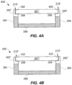
- FIGs. 4A and 4B are cross-sectional views of electronic device housings according to other embodiments that are similar to the electronic device housing 200 illustrated in FIG. 2A but which have different edge geometries for the outer device housing.
- FIG. 4A is a cross-sectional view of an electronic device housing 400 according to one embodiment.
- the electronic device housing 400 is the same as the electronic device housing 200 illustrated in FIG. 2A except that the edges 402 of the outer housing member 401' have been chamfered (or flattened).
- the protective side member 202' is molded against the edges of the outer housing member 401', including the chamfered edges 402.
- the outer exposed interface 210' between the sides (e.g., edges 402) of the outer housing member 201' and the peripheral side member 202' is essentially gap-free even though the edges 402 of the protective side member 202' are chamfered.
- FIG. 4B is a cross-sectional view of an electronic device housing 420 according to one embodiment.
- the electronic device housing 420 is the same as the electronic device housing 200 illustrated in FIG. 2A except that the edges 422 of the outer housing member 401" have been rounded.
- the protective side member 202" is molded against the edges of the outer housing member 401 ", including the rounded edges 422.
- the outer exposed interface 210" between the sides (e.g., edges 422) of the outer housing member 201" and the peripheral side member 202" is essentially gap-free even though the edges 422 of the protective side member 202" are rounded.
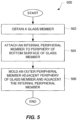
- FIG. 5 is a flow diagram of a housing formation process 500 according to one embodiment.
- the housing formation process 500 can operate to produce a housing for an electronic device, or at least a portion of such a housing.
- the housing formation process 500 can initially obtain 502 a glass member to be utilized with the housing for the electric device.
- the glass member to be utilized is a significant outer surface for the housing.
- the glass member can correspond to a top surface for the housing.
- the glass member can correspond to a bottom surface for the housing.
- the glass member is typically thin, particularly when the housing being formed is for a portable electronic device.
- the glass member has a thickness of less than 5 mm, and in another embodiment, the glass member has a thickness of less than 1 mm.
- an internal peripheral member can be attached 504 to the periphery of a bottom surface of the glass member.
- the internal peripheral member is attached 504 to the bottom surface of the glass member using an adhesive, though other means can be used, such as mechanical features (e.g., undercuts or interlocks).
- an outer peripheral member can be formed 506, e.g., molded, adjacent the periphery of the glass member and adjacent the inner peripheral member.
- the outer peripheral member provides an exposed outer surface for the housing.
- the outer peripheral member provides a thin protective later of material tightly adjacent the periphery of the glass member.
- the outer peripheral member can chemically bond with the inner peripheral member.
- the inner peripheral member and/or the outer peripheral member can be secured to a support structure for the housing so that the glass member is able to be mechanically secured to the housing.
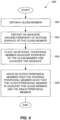
- FIG. 6 a flow diagram of a housing formation process 600 according to one embodiment.
- the housing formation process 600 can operate to produce a housing for an electronic device, or at least a portion of such a housing.
- the housing formation process 600 can initially obtain 602 a glass member.
- the glass member is to serve as a significant outer surface for the housing.
- the glass member can correspond to a top surface for the housing.
- the glass member can correspond to a bottom surface for the housing.
- the glass member is typically thin, particularly when used with portable electronic devices. In one embodiment, the glass member has a thickness of less than 5 mm, or more particularly less than 1 mm.
- an adhesive can be deposited 604 around a periphery of a bottom surface of the glass member.
- the glass member has a top surface that can represent an outer surface for the housing, and a bottom surface that is an inner surface that is not exposed.
- the adhesive being deposited 604 can be a thermally activated adhesive.
- the manner by which the adhesive is deposited can vary.
- the adhesive can be deposited 604 by forming a ring-like pattern of adhesive that can be placed around the periphery of the bottom surface of the glass member.
- the adhesive can be screen printed onto the periphery of the bottom surface of the glass member.
- an internal peripheral member can be placed 606 to the periphery of the glass member and adjacent the adhesive.
- the internal peripheral member can be secured to the bottom surface of the glass member using an adhesive, though other means can be used, such as mechanical features (e.g., undercuts or interlocks).
- the internal peripheral member can also be placed 606 by molding the internal peripheral member in place. In one embodiment, if the adhesive is thermally activated, the molding can also serve to activate the thermally activated adhesive so that a strong bond can be provided to the glass member and the internal peripheral member.
- an outer peripheral member can be molded 608 over the internal peripheral member such that the outer peripheral member is formed adjacent the periphery of the glass member and adjacent the inner peripheral member.
- the outer peripheral member provides an exposed outer surface for the housing.
- the outer peripheral member provides a thin protective later of material tightly adjacent the periphery of the glass member.
- the outer peripheral member can chemically bond with the inner peripheral member.
- a thermally activated adhesive could be used between the internal peripheral member and the outer peripheral member (or between the glass member and the outer peripheral member), and the molding of the outer peripheral member in place can also serve to activate the thermally activated adhesive so that a strong bond can be provided the inner peripheral member (and/or the glass member).
- the inner peripheral member and/or the outer peripheral member can be secured to a support structure for the housing so that the glass member is able to be mechanically secured to the housing.
- the peripheral members could be secured to the support structure by chemical bonding and/or mechanical features (e.g., undercuts or interlocks).
- FIG. 7A is a cross-sectional view of an electronic device housing 700 according to another embodiment.
- the electronic device housing 700 includes an outer housing member 701 supported and protected by an inner protective side member 702 and an outer protective side member 703.
- the inner protective side member 702 being positioned tightly adjacent sides of the outer housing member 701.
- the inner protective side member 702 can provide a thin layer of material positioned tightly adjacent sides of the outer housing member 701, thereby buffering impact at the sides of the outer housing member 701.
- the outer protective side member 703 being positioned tightly adjacent the sides of the inner protective side member 702 as well as the sides of the outer housing member 701.
- the outer and inner protective side members 702, 703 can individually or in combination provide a thin layer of material positioned tightly adjacent sides of the outer housing member 701, thereby buffering impact at the sides of the outer housing member 701.
- One or both of the inner and outer protective side members 702, 703 can also support the outer housing member 701 and serve to secure the outer housing member 701 to other portions of the electronic device housing 700.
- the outer protective side member 703 (and possibly also the inner protective side member 702) extends around all sides of the outer housing member 701. In another embodiment, the outer protective side member 703 (and possibly also the inner protective side member 702) extends around those of the sides of the outer housing member 701 that would otherwise be exposed.
- the outer housing member 701 can be secured to a support structure 704 of the electronic device housing 700.
- the support structure 704 can, for example, be an outer periphery member for the electronic device housing 700.
- the support structure 704 can couple to another outer housing member 706, which can be formed differently than the outer housing member 701.
- the inner protective side member 702 can be secured tightly adjacent the sides of the outer housing member 701 using an adhesive 708.
- the adhesive 708 can be applied as a layer of adhesive that is provided around a periphery of an inner side of the outer housing member 701. The adhesive 708 can thus serve to secure the inner protective side member 702 against the sides of the outer housing member 701.
- the outer protective side member 703 can be molded in place around at least a portion of the inner protective side member 702 as adjacent at least a portion of the sides of the outer housing member 701 so as to be tightly adjacent the sides of the outer housing member 701.
- the outer exposed interface 710 between the sides (e.g., edges) of the outer housing member 701 and the outer peripheral side member 703 is essentially gap-free.
- the outer protective side member 702 can be chemically bonded to at least a portion of the inner protective side member 702.
- the molding of the outer protective side member 703 can also serve to activate the thermally activated adhesive 708 so that a strong bond can be provided to the outer housing member 701 and the inner peripheral protective side member 702 via the adhesive 708.
- An internal space 712 is provided internal to the electronic device housing 700 whereby various electrical components can be attached, affixed or placed so as to provide electronic operations for the electronic device.
- the various members, parts or assemblies of the electronic device housing 700 can be formed of any of a variety of materials, e.g., glass, polymers or metal.
- the outer housing member 701 is glass
- the protective side members 702, 703 can be formed from a polymer (e.g., thermoplastic)
- the support structure 704 can be formed from metal or polymer (e.g., plastic)
- the another outer housing member 706 can be formed from glass, polymer (e.g., plastic) or metal.
- the protective side member 702 can be a structurally strengthened polymer (e.g., thermoplastic).
- the protective side member 702 can be polymer, such as polyarylamide, nylon or polycarbonate, which can be structurally strengthened by including glass fibers.
- some examples of some structurally strengthened polymers include 50% glass filled nylon and 30% glass filled polycarbonate.
- FIG. 7B is a cross-sectional assembly diagram for the electronic device housing 700 shown in FIG. 7A , according to one embodiment.
- the outer housing member 701 has a top surface 714 and a bottom surface 716.
- the bottom surface 716 of the outer housing member 701 has adhesive 708 applied as a layer of adhesive that is provided around a periphery of the bottom surface 716 of the outer housing member 701.
- the inner protective side member 702 can then be secured adjacent the sides of the outer housing member 701. More particularly, the inner protective side member 702 can be secured to the inner protective side member 702 using the adhesive 708 on the bottom surface 716 of the outer housing member 701.
- the outer protective side member 703 can be molded adjacent at least a portion of the sides of the outer housing member 701 and adjacent or over one or more sides of the inner protective side member 702. The molding process can also lead to chemical bonding of the outer protective side member 703 and the inner protective side member 702.
- the outer protective side member 703 can also be adjacent and secured to an upper side portion 718 of the support structure 704.
- the outer protective side member 703 is provided at the sides (i.e., edges) of the outer housing member 701, the outer protective side member 703 (alone or in combination with the inner protective side member 702) provides a buffer layer (e.g., bumper) that dampens impact induced at the sides of the outer housing member 701 of the electronic device housing 700.
- a buffer layer e.g., bumper
- FIG. 7C is a cross-sectional view of an electronic device housing 720 according to one embodiment.
- the electronic device housing 720 includes a first outer housing member 701 supported and protected by a first inner protective side member 702 and a first outer protective side member.
- the first inner protective side member 702 is positioned tightly adjacent sides of the first outer housing member 701.
- the outer protective side member 703 being positioned tightly adjacent the sides of the first inner protective side member 702 as well as the sides of the first outer housing member 701.
- the first outer and inner protective side members 702, 703 can individually or in combination provide a thin layer of material positioned tightly adjacent sides of the first outer housing member 701, thereby buffering impact at the sides of the first outer housing member 701.
- first inner and outer protective side members 702, 703 can also support the first outer housing member 701 and serve to secure the first outer housing member 701 to other portions of the electronic device housing 720.
- first outer protective side member 703 (and possibly also the first inner protective side member 702) extends around all sides of the first outer housing member 701.
- first outer protective side member 703 (and possibly also the first inner protective side member 702) extends around those of the sides of the first outer housing member 701 that would otherwise be exposed.
- the first inner protective side member 702 can be secured tightly adjacent the sides of the first outer housing member 701 using an adhesive 708.
- the adhesive 708 can be applied as a layer of adhesive that is provided around a periphery of an inner side of the first outer housing member 701. The adhesive 708 can thus serve to secure the first inner protective side member 702 against the sides of the first outer housing member 701.
- the first outer protective side member 703 can be molded in place around at least a portion of the first inner protective side member 702 as adjacent at least a portion of the sides of the first outer housing member 701 so as to be tightly adjacent the sides of the outer housing member 701.
- the outer exposed interface 710 between the sides (e.g., edges) of the first outer housing member 701 and the first outer peripheral side member 703 is essentially gap-free.
- the first outer protective side member 703 can be chemically bonded to at least a portion of the first inner protective side member 702.
- the adhesive 708 is thermally activated
- the molding of the first outer protective side member 703 can also serve to activate the thermally activated adhesive 708 so that a strong bond can be provided to the first outer housing member 701 and the first inner peripheral protective side member 702 via the adhesive 708.
- the electronic device housing 720 can also include an internal structure 722 that is integral with or secured to the support structure 704.
- the internal structure 722 can be secured to an inner surface of the support structure 704 such that it is offset from front and back planar boundaries of the support structure 704 (which may be an outer periphery member). As shown in FIG. 7C , the internal structure 722 can be secured at the mid-point of the height of the support structure 704.
- a first internal space 724 is provided internal to the electronic device housing 720 whereby various electrical components can be attached, affixed or placed so as to provide electronic operations for the electronic device.
- the electronic device housing 720 can also include similar structures on an opposite side of the electronic device housing 720.
- the electronic device housing 720 can further include a second outer housing member 726 supported and protected by a second inner protective side member 728 and a second outer protective side member 729.
- the second inner protective side member 728 can be positioned tightly adjacent sides of the second outer housing member 726.
- the second outer protective side member 729 can be positioned tightly adjacent the sides of the inner protective side member 702 as well as the sides of the second outer housing member 726.
- the second outer and inner protective side members 728, 729 can individually or in combination provide a thin layer of material positioned tightly adjacent sides of the second outer housing member 726, thereby buffering impact at the sides of the second outer housing member 726.
- One or both of the second inner and outer protective side members 728, 729 can also support the second outer housing member 726 and serve to secure the second outer housing member 726 to other portions of the electronic device housing 720.
- the second outer protective side member 729 (and possibly also the inner protective side member 728) extends around all sides of the second outer housing member 726.
- the second outer protective side member 729 (and possibly also the second inner protective side member 728) extends around those of the sides of the second outer housing member 726 that would otherwise be exposed.
- the second inner protective side member 728 can be secured tightly adjacent the sides of the second outer housing member 726 using an adhesive 730.
- the adhesive 730 can be applied as a layer of adhesive that is provided around a periphery of an inner side of the second outer housing member 726. The adhesive 730 can thus serve to secure the second inner protective side member 728 against the sides of the second outer housing member 726.
- the second outer protective side member 729 can be molded in place around at least a portion of the second inner protective side member 728 and adjacent at least a portion of the sides of the second outer housing member 726 so as to be tightly adjacent the sides of the second outer housing member 726.
- the outer exposed interface 731 between the sides (e.g., edges) of the second outer housing member 726 and the second outer peripheral side member 729 is essentially gap-free.
- the second outer protective side member 729 can be chemically bonded to at least a portion of the second inner protective side member 728.
- the adhesive 730 is thermally activated
- the molding of the second outer protective side member 729 can also serve to activate the thermally activated adhesive 730 so that a strong bond can be provided to the second outer housing member 726 and the second inner peripheral protective side member 728 via the adhesive 730.
- An internal space 712 is provided internal to the electronic device housing 700 whereby various electrical components can be attached, affixed or placed so as to provide electronic operations for the electronic device.
- a second internal space 732 is provided internal to the electronic device housing 720 (between the internal structure 722 and the second outer housing member 726) whereby various electrical components can be attached, affixed or placed so as to provide electronic operations for the electronic device.
- the second internal space 732 can be separate from or joined with the first internal space 724.
- the various members, parts or assemblies of the electronic device housing 720 can be formed of any of a variety of materials, e.g., glass, polymers or metal.
- the outer housing members 701, 726 are glass
- the protective side members 702, 703, 728, 729 can be formed from a polymer (e.g., thermoplastic)
- the support structures 704, 722 can be formed from metal or polymer (e.g., plastic).
- the protective side members 702, 703, 728, 729 can be a structurally strengthened polymer (e.g., thermoplastic).
- the protective side members 702, 703, 728, 729 can be polymer, such as polyarylamide, nylon or polycarbonate, which can be structurally strengthened by including glass fibers.
- some examples of some structurally strengthened polymers include 50% glass filled nylon and 30% glass filled polycarbonate.
- first outer housing member 701 can represent a top outer surface for the portable electronic device
- second outer surface housing 726 can represent a bottom outer surface housing.
- both the first outer housing member 701 and the second outer housing member 726 are glass (e.g., glass covers).
- the protective side members discussed above are typically thin layers of material positioned tightly adjacent sides of the outer housing member, thereby buffering impact at the sides of the outer housing members.
- the protective side members are to be strong; hence, a structurally strengthened polymer, such as polyarylamide, can be utilized.
- the polyarylamide can be strengthened by containing glass fibers.
- IXEF polyarylamide PARA
- Solvay Advanced Polymers L.L.C which can contain glass fiber reinforcement.
- the protective side members are tightly adjacent sides of the outer housing member, the respective materials used for the protective side members and the outer housing member.
- the Coefficient of Thermal Expansion (CTE) of the respective materials can produce undesired stress on the sides of the outer housing member.
- CTE Coefficient of Thermal Expansion
- the CTE of the material for the protective side members would be about 10 millimeters/meter/°C.
- plastics tend to have CTE's (e.g., roughly 100 millimeters/meter/°C) that are dramatically higher than that of glass
- some manufactured polymers such as polyarylamide, can have CTE's (e.g., roughly 30 millimeters/meter/°C) that are substantially closer to that of glass and thereby would, if used, induce less stress on the sides of the outer housing member.
- a manufactured polymer for such use could have a CTE less than or equal to about 50 millimeters/meter/°C, and in another embodiment, a manufactured polymer for such use could have a CTE less than or equal to about 35 millimeters/meter/°C.
- additive can be added to a polymer so to bring is CTE closer to that of glass.
- the additives can be particles or fibers which can be formed from glass or ceramic.
- the thickness of the protective side member can be thin, for example, the thickness can be on the order of about 1 mm or less in one embodiment.
- the protective side materials can be formed from multiple materials that can be alternated, intertwined or layered.
- the later of material against the edges of the outer housing member of glass can have a CTE relatively close to that of glass while an outer layer can have a higher CTE can permit a greater range of material, such as polymers (e.g., plastics).
- the protective side members are able to be thin yet be cosmetically unintrusive.
- the thickness (t1) for the protective side member can be less than 1 mm (e.g., 0.8 mm).
- the thickness (t2) of the outer housing member can be less than 5 mm (e.g., 1 mm).
- these thicknesses are exemplary and vary with the size of the electronic device housing and with desired strength.
- Using a strengthened material for the protective side members as noted above can also be advantageous. Nevertheless, the provisioning of thin protective side members for outer housing members, such as glass covers, facilitates providing portable electronic device housings that are compact and thin yet resistant to side impact damage to the outer housing members.
- a glass member for which a component e.g., peripheral side member
- a component e.g., peripheral side member
- a metal mold is normally used in molding.
- the metal mold can damage (e.g., scratch) a glass member during molding.
- the metal mold i.e., its inner surfaces
- the coating can, for example, be a thin layer of polytetrafluoroethylene (PTFE) or polyimide film.
- An electronic device enclosure comprising: a glass cover for a top surface for the electronic device enclosure; an adhesive deposited around a periphery of the glass cover; and a peripheral structure for providing a support surface for the glass cover and for providing side protective surfaces for the glass cover, the peripheral structure being at least partially secured to the glass cover by the adhesive.
- peripheral structure comprises a polymer strengthened by containing glass fibers.
- peripheral structure comprises a polymer
- the polymer includes additives such that the CTE of the peripheral structure is made closer to the CTE of the glass cover.
- peripheral structure is molded about the periphery of the glass cover and molded adjacent the adhesive, and wherein the adhesive includes a feature to which the peripheral structure is formed.
- peripheral structure is molded about the periphery of the glass cover and molded adjacent the adhesive, and wherein the metal support has at least one feature that provides a mechanical interlock with the peripheral structure after the peripheral structure has been molded.
- peripheral structure includes an inner peripheral member and an outer peripheral member, wherein the inner peripheral member is attached to the glass cover via the adhesive, and wherein at least the outer peripheral member is molded about at least a portion of the periphery of the glass cover and about at least a portion of the inner peripheral member.
- a method for assembling an electronic device comprising: obtaining a glass member having a top surface and a bottom surface, the top surface providing an outer surface for substantially all of a surface of the electronic device; depositing an adhesive layer around a periphery of the bottom surface of the glass member; aligning the glass member relative to a support structure for the electronic device; and molding a peripheral protective side portion for the electronic device, the peripheral protective side portion being molded adjacent the periphery of the glass member, adjacent the adhesive layer, and adjacent the support structure.
- a method as recited in clause 19, wherein the depositing of the adhesive layer comprises: screen printing the adhesive layer to the periphery of the bottom surface of the glass member.
- a method as recited in clause 19, wherein the depositing of the adhesive layer comprises: placing an adhesive film on at least a portion of the bottom surface of the glass member.
- a method for assembling an electronic device comprising: obtaining a glass member having a top surface and a bottom surface, the top surface providing an outer surface for substantially all of a surface of the electronic device; attaching an internal periphery member to a periphery of the bottom surface of the glass member; and molding an outer periphery member adjacent a periphery of the glass member and adjacent the internal periphery member.
- said molding comprises: obtaining a metal mold having an inner surface configured to form the outer periphery member for the electronic device; coating at least a portion of the inner surface of the metal mold; and injecting a molding material into the metal mold to form the outer periphery member for the electronic device.
Landscapes
- Engineering & Computer Science (AREA)
- Theoretical Computer Science (AREA)
- General Engineering & Computer Science (AREA)
- Computer Hardware Design (AREA)
- Physics & Mathematics (AREA)
- General Physics & Mathematics (AREA)
- Human Computer Interaction (AREA)
- Microelectronics & Electronic Packaging (AREA)
- Signal Processing (AREA)
- Casings For Electric Apparatus (AREA)
- Telephone Set Structure (AREA)
- Devices For Indicating Variable Information By Combining Individual Elements (AREA)
- Liquid Crystal (AREA)
Applications Claiming Priority (4)
| Application Number | Priority Date | Filing Date | Title |
|---|---|---|---|
| US12/944,671 US9235240B2 (en) | 2010-11-11 | 2010-11-11 | Insert molding around glass members for portable electronic devices |
| PCT/US2011/058999 WO2012064567A1 (fr) | 2010-11-11 | 2011-11-02 | Moulage d'insert autour d'éléments en verre pour dispositifs électroniques portatifs |
| EP11793528.8A EP2638449B1 (fr) | 2010-11-11 | 2011-11-02 | Moulage d'insert autour d'éléments en verre pour dispositifs électroniques portatifs |
| EP18171622.6A EP3376336B1 (fr) | 2010-11-11 | 2011-11-02 | Boîtier de dispositif électronique, dispositif électronique comprenant ce boîtier de dispositif électronique et méthode d'assemblage de ce dispositif électronique |
Related Parent Applications (2)
| Application Number | Title | Priority Date | Filing Date |
|---|---|---|---|
| EP18171622.6A Division EP3376336B1 (fr) | 2010-11-11 | 2011-11-02 | Boîtier de dispositif électronique, dispositif électronique comprenant ce boîtier de dispositif électronique et méthode d'assemblage de ce dispositif électronique |
| EP11793528.8A Division EP2638449B1 (fr) | 2010-11-11 | 2011-11-02 | Moulage d'insert autour d'éléments en verre pour dispositifs électroniques portatifs |
Publications (2)
| Publication Number | Publication Date |
|---|---|
| EP4340147A2 true EP4340147A2 (fr) | 2024-03-20 |
| EP4340147A3 EP4340147A3 (fr) | 2024-07-03 |
Family
ID=45217624
Family Applications (3)
| Application Number | Title | Priority Date | Filing Date |
|---|---|---|---|
| EP11793528.8A Not-in-force EP2638449B1 (fr) | 2010-11-11 | 2011-11-02 | Moulage d'insert autour d'éléments en verre pour dispositifs électroniques portatifs |
| EP18171622.6A Active EP3376336B1 (fr) | 2010-11-11 | 2011-11-02 | Boîtier de dispositif électronique, dispositif électronique comprenant ce boîtier de dispositif électronique et méthode d'assemblage de ce dispositif électronique |
| EP24155862.6A Pending EP4340147A3 (fr) | 2010-11-11 | 2011-11-02 | Boîtier de dispositif électronique, dispositif électronique comprenant ledit boîtier de dispositif électronique et procédé d'assemblage dudit dispositif électronique |
Family Applications Before (2)
| Application Number | Title | Priority Date | Filing Date |
|---|---|---|---|
| EP11793528.8A Not-in-force EP2638449B1 (fr) | 2010-11-11 | 2011-11-02 | Moulage d'insert autour d'éléments en verre pour dispositifs électroniques portatifs |
| EP18171622.6A Active EP3376336B1 (fr) | 2010-11-11 | 2011-11-02 | Boîtier de dispositif électronique, dispositif électronique comprenant ce boîtier de dispositif électronique et méthode d'assemblage de ce dispositif électronique |
Country Status (8)
| Country | Link |
|---|---|
| US (7) | US9235240B2 (fr) |
| EP (3) | EP2638449B1 (fr) |
| JP (1) | JP6175001B2 (fr) |
| KR (1) | KR101517709B1 (fr) |
| CN (2) | CN107708369B (fr) |
| AU (1) | AU2011326249B2 (fr) |
| TW (1) | TWI548604B (fr) |
| WO (1) | WO2012064567A1 (fr) |
Families Citing this family (76)
| Publication number | Priority date | Publication date | Assignee | Title |
|---|---|---|---|---|
| US8673163B2 (en) | 2008-06-27 | 2014-03-18 | Apple Inc. | Method for fabricating thin sheets of glass |
| US7810355B2 (en) | 2008-06-30 | 2010-10-12 | Apple Inc. | Full perimeter chemical strengthening of substrates |
| US8023261B2 (en) | 2008-09-05 | 2011-09-20 | Apple Inc. | Electronic device assembly |
| US20110019354A1 (en) * | 2009-03-02 | 2011-01-27 | Christopher Prest | Techniques for Strengthening Glass Covers for Portable Electronic Devices |
| JP5616907B2 (ja) | 2009-03-02 | 2014-10-29 | アップル インコーポレイテッド | ポータブル電子デバイスのガラスカバーを強化する技術 |
| US9778685B2 (en) * | 2011-05-04 | 2017-10-03 | Apple Inc. | Housing for portable electronic device with reduced border region |
| US8551283B2 (en) | 2010-02-02 | 2013-10-08 | Apple Inc. | Offset control for assembling an electronic device housing |
| US8607444B2 (en) * | 2010-03-06 | 2013-12-17 | Apple Inc. | Method for forming a housing of an electronic device |
| US9213451B2 (en) | 2010-06-04 | 2015-12-15 | Apple Inc. | Thin glass for touch panel sensors and methods therefor |
| US10189743B2 (en) | 2010-08-18 | 2019-01-29 | Apple Inc. | Enhanced strengthening of glass |
| US8824140B2 (en) | 2010-09-17 | 2014-09-02 | Apple Inc. | Glass enclosure |
| CN102448265B (zh) * | 2010-09-30 | 2015-01-07 | 赛恩倍吉科技顾问(深圳)有限公司 | 防尘结构及具有该防尘结构的便携式电子装置 |
| US9235240B2 (en) | 2010-11-11 | 2016-01-12 | Apple Inc. | Insert molding around glass members for portable electronic devices |
| US9182789B2 (en) | 2011-03-01 | 2015-11-10 | Apple Inc. | Transparent electronic device components with opaque edge coverings |
| US10781135B2 (en) | 2011-03-16 | 2020-09-22 | Apple Inc. | Strengthening variable thickness glass |
| US9725359B2 (en) | 2011-03-16 | 2017-08-08 | Apple Inc. | Electronic device having selectively strengthened glass |
| US9128666B2 (en) * | 2011-05-04 | 2015-09-08 | Apple Inc. | Housing for portable electronic device with reduced border region |
| US9944554B2 (en) | 2011-09-15 | 2018-04-17 | Apple Inc. | Perforated mother sheet for partial edge chemical strengthening and method therefor |
| WO2013043462A1 (fr) | 2011-09-19 | 2013-03-28 | Speculative Product Design, Llc | Boîtier destiné à un dispositif électronique portatif et comprenant un film thermoformé surmoulé |
| US9516149B2 (en) | 2011-09-29 | 2016-12-06 | Apple Inc. | Multi-layer transparent structures for electronic device housings |
| US10144669B2 (en) | 2011-11-21 | 2018-12-04 | Apple Inc. | Self-optimizing chemical strengthening bath for glass |
| US10133156B2 (en) | 2012-01-10 | 2018-11-20 | Apple Inc. | Fused opaque and clear glass for camera or display window |
| US8773848B2 (en) | 2012-01-25 | 2014-07-08 | Apple Inc. | Fused glass device housings |
| US9946302B2 (en) | 2012-09-19 | 2018-04-17 | Apple Inc. | Exposed glass article with inner recessed area for portable electronic device housing |
| US9047044B2 (en) * | 2012-10-19 | 2015-06-02 | Apple Inc. | Trimless glass enclosure interface |
| TWI547230B (zh) * | 2012-12-06 | 2016-08-21 | 宏達國際電子股份有限公司 | 電子裝置與電子裝置之顯示元件的組裝方法 |
| US20140239781A1 (en) | 2013-02-25 | 2014-08-28 | Motorola Mobility Llc | Electronic Device Having a Display and Method of Manufacture |
| US9871898B2 (en) | 2013-05-08 | 2018-01-16 | Apple Inc. | Ceramic cover for electronic device housing |
| US9459661B2 (en) | 2013-06-19 | 2016-10-04 | Apple Inc. | Camouflaged openings in electronic device housings |
| CN103342068B (zh) * | 2013-06-25 | 2015-07-15 | 谢虹 | 一种荧光板 |
| US9573843B2 (en) | 2013-08-05 | 2017-02-21 | Corning Incorporated | Polymer edge-covered glass articles and methods for making and using same |
| JP6023122B2 (ja) * | 2013-12-24 | 2016-11-09 | 京セラ株式会社 | 電子機器 |
| US9220171B2 (en) * | 2014-01-13 | 2015-12-22 | Htc Corporation | Method of fabricating housing, housing, and electronic apparatus |
| KR102145892B1 (ko) | 2014-01-22 | 2020-08-19 | 엘지전자 주식회사 | 디스플레이 장치 |
| US9886062B2 (en) | 2014-02-28 | 2018-02-06 | Apple Inc. | Exposed glass article with enhanced stiffness for portable electronic device housing |
| CN105260043A (zh) * | 2014-06-13 | 2016-01-20 | 宸鸿科技(厦门)有限公司 | 具有指纹识别功能的触控面板 |
| CN105468187A (zh) * | 2014-06-18 | 2016-04-06 | 宸鸿科技(厦门)有限公司 | 具有指纹识别功能的触控面板 |
| CN104133310A (zh) * | 2014-08-22 | 2014-11-05 | 深圳市中兴移动通信有限公司 | 一种无边框显示装置 |
| CN104181716A (zh) * | 2014-08-22 | 2014-12-03 | 深圳市中兴移动通信有限公司 | 一种无边框显示装置 |
| CN105589587B (zh) * | 2014-10-21 | 2018-10-26 | 宸鸿科技(厦门)有限公司 | 透明复合基板与其制备方法及触控面板 |
| CN105528101A (zh) * | 2014-10-21 | 2016-04-27 | 宸鸿科技(厦门)有限公司 | 触控面板及其立体盖板结构 |
| US10590032B2 (en) | 2014-10-22 | 2020-03-17 | Corning Incorporated | Methods and apparatus for improving reliability of cover substrate against impact fractures |
| CN104363730A (zh) * | 2014-11-25 | 2015-02-18 | 深圳市华星光电技术有限公司 | 一种玻璃盖板结构 |
| CN106465553A (zh) * | 2015-01-21 | 2017-02-22 | 华为技术有限公司 | 一种电子设备 |
| KR102312783B1 (ko) * | 2015-04-06 | 2021-10-15 | 삼성디스플레이 주식회사 | 표시 장치 |
| CN104834399B (zh) * | 2015-04-15 | 2018-06-22 | 业成光电(深圳)有限公司 | 触控显示模组 |
| KR102388104B1 (ko) * | 2015-08-13 | 2022-04-20 | 삼성디스플레이 주식회사 | 표시 장치 및 커버 부재 제조방법 |
| KR102672500B1 (ko) | 2015-08-31 | 2024-06-07 | 코닝 인코포레이티드 | 전자 디바이스의 유리 디스플레이를 보호하는 장치 및 방법 |
| KR102358304B1 (ko) | 2015-11-13 | 2022-02-04 | 삼성전자 주식회사 | 유니 바디 하우징을 갖는 전자 장치 및 그 제조방법 |
| TWI758263B (zh) | 2015-11-19 | 2022-03-21 | 美商康寧公司 | 顯示螢幕保護器 |
| KR102147366B1 (ko) * | 2016-01-26 | 2020-08-24 | 구글 엘엘씨 | 전자 장치용 유리 인클로저 |
| CN105704268A (zh) * | 2016-01-29 | 2016-06-22 | 华为技术有限公司 | 盖板玻璃组件 |
| US10459266B2 (en) * | 2016-08-04 | 2019-10-29 | Boe Technology Group Co., Ltd. | Display module, display apparatus having the same, and fabricating method thereof |
| US9870033B1 (en) | 2016-08-30 | 2018-01-16 | Apple Inc. | Sensor assemblies for electronic devices |
| KR102208888B1 (ko) * | 2016-09-09 | 2021-01-27 | 후아웨이 테크놀러지 컴퍼니 리미티드 | 패키징 방법, 패키징 장치, 및 단말 |
| JP6531754B2 (ja) * | 2016-12-21 | 2019-06-19 | カシオ計算機株式会社 | 機器ケース及び時計 |
| WO2018136090A1 (fr) * | 2017-01-23 | 2018-07-26 | Hewlett-Packard Development Company, L.P. | Boîtiers de dispositifs électroniques |
| TWI749160B (zh) | 2017-01-31 | 2021-12-11 | 美商康寧公司 | 具有工程應力分佈的塗層玻璃基底製品及包含其之消費性電子產品 |
| JP6159902B1 (ja) * | 2017-03-15 | 2017-07-05 | 京セラ株式会社 | 電子機器 |
| DE102018002977A1 (de) * | 2017-05-11 | 2018-11-15 | Wika Alexander Wiegand Se & Co. Kg | Messgerät |
| TWI784093B (zh) | 2017-11-29 | 2022-11-21 | 美商康寧公司 | 製造塗佈玻璃系部件的方法 |
| WO2019130756A1 (fr) * | 2017-12-26 | 2019-07-04 | ソニー株式会社 | Dispositif d'affichage |
| KR102240876B1 (ko) * | 2018-06-12 | 2021-04-16 | 삼성디스플레이 주식회사 | 윈도우 및 이를 포함하는 표시 장치 |
| US12474739B2 (en) | 2018-07-03 | 2025-11-18 | Samsung Display Co., Ltd. | Window and display device comprising the same |
| KR102040318B1 (ko) * | 2018-08-08 | 2019-11-04 | 삼성전자주식회사 | 전자 장치 및 이에 사용되는 하우징 구조물 |
| CN110933881A (zh) * | 2018-09-19 | 2020-03-27 | 比亚迪股份有限公司 | 用于电子设备的壳体组件和电子设备 |
| KR102630315B1 (ko) * | 2018-10-24 | 2024-01-30 | 삼성디스플레이 주식회사 | 표시 장치 및 이를 이용한 전자장치 제조방법 |
| KR102551690B1 (ko) * | 2018-12-06 | 2023-07-05 | 삼성전자주식회사 | 접착 구조를 포함하는 전자 장치 |
| KR102594548B1 (ko) * | 2019-01-02 | 2023-10-27 | 삼성디스플레이 주식회사 | 윈도우, 윈도우의 제조 방법 및 윈도우를 포함하는 표시 장치 |
| KR102730322B1 (ko) | 2019-04-18 | 2024-11-15 | 삼성전자주식회사 | 디스플레이를 포함하는 전자 장치 |
| WO2020264230A1 (fr) | 2019-06-28 | 2020-12-30 | Corning Incorporated | Procédés et appareil de fabrication d'un article à base de verre |
| CN110972419B (zh) * | 2019-10-25 | 2021-02-12 | 芜湖舜富精密压铸科技有限公司 | 利用缓冲组件加强防震效果的新能源汽车控制器箱体 |
| KR102870067B1 (ko) * | 2019-12-20 | 2025-10-16 | 삼성전자주식회사 | 통기 및 방수 구조를 포함하는 웨어러블 전자 장치 |
| CN111405089B (zh) * | 2020-03-12 | 2021-06-15 | Oppo广东移动通信有限公司 | 显示模组及其制造方法,以及电子设备 |
| CN116529211B (zh) | 2020-09-25 | 2026-03-24 | 康宁股份有限公司 | 具有改善的掉落性能的玻璃基制品的应力分布曲线 |
| US11839043B2 (en) * | 2021-04-29 | 2023-12-05 | Robert Bosch Llc | Electronic device with sealed housing |
Family Cites Families (142)
| Publication number | Priority date | Publication date | Assignee | Title |
|---|---|---|---|---|
| US2269554A (en) | 1938-03-01 | 1942-01-13 | Holophane Co Inc | Luminaire |
| US4403224A (en) | 1982-01-22 | 1983-09-06 | Exxon Research And Engineering Co. | Smudge-free electrosensitive recording medium and method of inhibiting smudge formation on said medium |
| CH654168GA3 (fr) | 1983-08-22 | 1986-02-14 | ||
| JPH0694848B2 (ja) | 1986-02-27 | 1994-11-24 | トヨタ自動車株式会社 | Lpgエンジンの空燃比学習制御方法 |
| US4995941A (en) | 1989-05-15 | 1991-02-26 | Rogers Corporation | Method of manufacture interconnect device |
| JP2938933B2 (ja) | 1990-05-24 | 1999-08-25 | ポリマテック株式会社 | 表示板一体成型法 |
| US6266685B1 (en) | 1991-07-11 | 2001-07-24 | Intermec Ip Corp. | Hand-held data collection system with stylus input |
| JPH0694848A (ja) | 1991-08-23 | 1994-04-08 | Casio Comput Co Ltd | 電子機器の表示ガラス取付構造 |
| US5456955A (en) | 1992-12-11 | 1995-10-10 | Illuminated Display Division Of Bell Industries, Inc. | Method and apparatus for forming an illuminated display |
| US5394306A (en) | 1993-09-07 | 1995-02-28 | Norand Corporation | Shock absorbent packaging apparatus |
| US5514319A (en) | 1994-07-27 | 1996-05-07 | Young; Wen-Kuei | Method of fabricating a rubber keypad |
| US5613237A (en) | 1994-10-17 | 1997-03-18 | Motorola, Inc. | Housing latch system utilizing an elastomeric interlocking band |
| US5867149A (en) | 1995-08-14 | 1999-02-02 | Intertactile Technologies Corporation | Switch key image display and operator/circuit interface |
| DE19529943C1 (de) | 1995-08-16 | 1997-03-20 | Sekurit Saint Gobain Deutsch | Verbundglasscheibe mit IR-reflektierenden Eigenschaften |
| US5681515A (en) | 1996-04-12 | 1997-10-28 | Motorola, Inc. | Method of fabricating an elastomeric keypad |
| GB2314230B (en) | 1996-06-12 | 2000-04-26 | Nec Technologies | Mobile phone hand set |
| US6058293A (en) | 1997-09-12 | 2000-05-02 | Ericsson, Inc. | Frame structure for cellular telephones |
| US6510226B1 (en) | 1997-11-24 | 2003-01-21 | Lucent Technologies Inc. | Dual network housing device |
| KR100595926B1 (ko) | 1998-01-26 | 2006-07-05 | 웨인 웨스터만 | 수동 입력 통합 방법 및 장치 |
| US7800592B2 (en) | 2005-03-04 | 2010-09-21 | Apple Inc. | Hand held electronic device with multiple touch sensing devices |
| US6532152B1 (en) | 1998-11-16 | 2003-03-11 | Intermec Ip Corp. | Ruggedized hand held computer |
| JP2000194269A (ja) * | 1998-12-28 | 2000-07-14 | Casio Comput Co Ltd | 筐体の構造 |
| JP3975627B2 (ja) | 1998-12-31 | 2007-09-12 | カシオ計算機株式会社 | データ通信装置 |
| EP1033633B1 (fr) | 1999-03-03 | 2003-10-08 | Rolex Sa | Dispositif de fixation étanche d'une glace sur une boite de montre |
| JP2001337743A (ja) | 2000-05-24 | 2001-12-07 | Hitachi Ltd | 情報処理装置 |
| JP2001337225A (ja) | 2000-05-29 | 2001-12-07 | Nitto Denko Corp | 積層光学素子及び液晶表示装置 |
| TW466860B (en) | 2000-06-22 | 2001-12-01 | Hon Hai Prec Ind Co Ltd | Protection lens of display and the manufacturing method thereof |
| JP3501218B2 (ja) | 2000-08-11 | 2004-03-02 | 日本電気株式会社 | フラットパネル表示モジュール及びその製造方法 |
| DE10041786A1 (de) | 2000-08-25 | 2002-03-14 | Siemens Ag | Transparente Blende für eine Anzeigevorrichtung sowie Mobilfunkgerät mit einer solchen Blende |
| JP2002196312A (ja) | 2000-12-25 | 2002-07-12 | Hitachi Ltd | 液晶表示装置 |
| US6965789B2 (en) | 2000-12-29 | 2005-11-15 | Vertu Limited | Portable communication device |
| US7012189B2 (en) | 2001-03-28 | 2006-03-14 | Apple Computer, Inc. | Computer enclosure |
| US20020172017A1 (en) | 2001-05-21 | 2002-11-21 | Tarnowski Thomas J. | Functional enclosure for a personal electronic device |
| US20030006128A1 (en) | 2001-07-03 | 2003-01-09 | Giles John T. | Two-shot molded backlit switch cap and method of manufacture |
| JP2003076305A (ja) * | 2001-08-31 | 2003-03-14 | Casio Comput Co Ltd | 紫外線発光装置及び電子機器 |
| KR100401192B1 (ko) | 2001-09-05 | 2003-10-10 | 삼성전자주식회사 | 복사특성을 조절할 수 있는 폴더형 단말기 |
| US7046230B2 (en) | 2001-10-22 | 2006-05-16 | Apple Computer, Inc. | Touch pad handheld device |
| US7158376B2 (en) | 2001-11-19 | 2007-01-02 | Otter Products, Llc | Protective enclosure for an interactive flat-panel controlled device |
| EP1316978B1 (fr) | 2001-11-28 | 2007-08-01 | Polymatech Co., Ltd. | Feuille à boutons poussoirs |
| EP1482065B1 (fr) | 2002-03-01 | 2011-04-27 | Showa Denko K.K. | Procede de production d'une plaque en alliage al-mg-si |
| JP3961320B2 (ja) | 2002-03-15 | 2007-08-22 | セイコーインスツル株式会社 | バングルタイプバンドを備えた腕装着型携帯装置 |
| EP1491940B1 (fr) | 2002-03-28 | 2007-06-06 | Sanyo Electric Co., Ltd. | Dispositif d'affichage a cristaux liquides |
| US7073916B2 (en) | 2002-04-29 | 2006-07-11 | Hewlett-Packard Development Company, L.P. | Key for use in low light conditions |
| US6650092B1 (en) | 2002-05-24 | 2003-11-18 | Motorola, Inc. | System and method for regulating a power system with feedback using current sensing |
| JP3910112B2 (ja) | 2002-06-21 | 2007-04-25 | シャープ株式会社 | カメラ付携帯電話機 |
| US20040022017A1 (en) | 2002-08-02 | 2004-02-05 | Michael Chuang | Universal coupling cassette for computer facilities |
| KR100872242B1 (ko) | 2002-08-29 | 2008-12-05 | 엘지전자 주식회사 | 휴대 가능한 복합형 컴퓨터 |
| US6876543B2 (en) | 2003-03-07 | 2005-04-05 | Motorola, Inc. | Housing for a communication device and method assembling the same |
| JP4260519B2 (ja) | 2003-03-31 | 2009-04-30 | シャープ株式会社 | 液晶表示装置 |
| US7499040B2 (en) | 2003-08-18 | 2009-03-03 | Apple Inc. | Movable touch pad with added functionality |
| US7145766B2 (en) | 2003-10-16 | 2006-12-05 | Hewlett-Packard Development Company, L.P. | Display for an electronic device |
| US6842288B1 (en) | 2003-10-30 | 2005-01-11 | 3M Innovative Properties Company | Multilayer optical adhesives and articles |
| US7118801B2 (en) | 2003-11-10 | 2006-10-10 | Gore Enterprise Holdings, Inc. | Aerogel/PTFE composite insulating material |
| US7236588B2 (en) | 2003-12-12 | 2007-06-26 | Nokia Corporation | Interlocking cover for mobile terminals |
| US7796187B2 (en) | 2004-02-20 | 2010-09-14 | Flextronics Ap Llc | Wafer based camera module and method of manufacture |
| US6980095B2 (en) | 2004-03-17 | 2005-12-27 | Lear Corporation | Illuminated vehicle remote entry device |
| TWI302431B (en) | 2004-06-25 | 2008-10-21 | Asustek Comp Inc | Electronic device with monitor protective function |
| JP3850847B2 (ja) | 2004-06-28 | 2006-11-29 | 株式会社東芝 | 電子機器の液晶表示装置保護構造 |
| US7724532B2 (en) | 2004-07-02 | 2010-05-25 | Apple Inc. | Handheld computing device |
| US20060090842A1 (en) * | 2004-11-01 | 2006-05-04 | Christophe Chervin | Joining of thermoplastics with other types of materials |
| JP4581726B2 (ja) | 2004-12-28 | 2010-11-17 | ソニー株式会社 | 表示装置および携帯機器 |
| US7403377B2 (en) | 2005-01-20 | 2008-07-22 | Hewlett-Packard Development Company, L.P. | Method of manufacture and an enclosure for a display for an electronic device |
| JP4613663B2 (ja) * | 2005-03-30 | 2011-01-19 | セイコーエプソン株式会社 | 電気光学装置および電気光学装置の製造方法、電子機器 |
| US20060239746A1 (en) | 2005-04-20 | 2006-10-26 | Ikeyinfinity Inc. | Systems and methods for computer input |
| US8611284B2 (en) | 2005-05-31 | 2013-12-17 | Qualcomm Incorporated | Use of supplemental assignments to decrement resources |
| DE102005027394A1 (de) | 2005-06-13 | 2006-12-14 | Tesa Ag | Doppelseitige Haftklebebänder zur Herstellung von LC-Displays mit lichtreflektierenden und -absorbierenden Eigenschaften |
| CN100517535C (zh) | 2005-07-08 | 2009-07-22 | 鸿富锦精密工业(深圳)有限公司 | 一种透光按键 |
| US7385806B2 (en) | 2005-07-27 | 2008-06-10 | Kim Liao | Combination housing of a notebook computer |
| EP1911809A4 (fr) | 2005-08-02 | 2010-05-19 | Unitika Ltd | Compositions de resine, procede de production de ces compositions, et article moule obtenu a partir de ces compositions |
| US7031148B1 (en) | 2005-08-04 | 2006-04-18 | Chia-Hao Lin | Notebook computer protector |
| KR101054111B1 (ko) * | 2006-02-09 | 2011-08-03 | 니혼샤신 인사츠 가부시키가이샤 | 보호패널을 부착한 전자기기 |
| CN101018458A (zh) | 2006-02-10 | 2007-08-15 | 深圳富泰宏精密工业有限公司 | 便携式电子装置密封结构 |
| US20070257398A1 (en) | 2006-05-04 | 2007-11-08 | Moncrieff Scott E | Laminated electronic components for insert molding |
| US7711256B2 (en) | 2006-09-01 | 2010-05-04 | Research In Motion Limited | Camera-steady focus requirements for preventing inconspicuous use of cameras on handheld mobile communication devices |
| JP5000243B2 (ja) | 2006-09-08 | 2012-08-15 | 京セラ株式会社 | 電子機器 |
| US7751199B2 (en) | 2006-09-11 | 2010-07-06 | Apple Inc. | Support tabs for protecting a circuit board from applied forces |
| CN101518168B (zh) * | 2006-09-22 | 2011-12-07 | 日本写真印刷株式会社 | 外罩壳体和该外罩壳体的制造方法及所使用的玻璃嵌入成形用模具 |
| TWM312363U (en) | 2006-10-20 | 2007-05-21 | Darfon Electronics Corp | Spraying paint jig for key cap |
| JP5087402B2 (ja) | 2006-10-24 | 2012-12-05 | パナソニック株式会社 | 表示装置付電子機器および携帯電話機 |
| US20080264548A1 (en) | 2006-11-28 | 2008-10-30 | Jian-Zhi Jay Zhang | Optical distortion removal |
| KR100810266B1 (ko) | 2006-12-14 | 2008-03-06 | 삼성전자주식회사 | 보강 부재를 구비하는 휴대용 단말기 |
| US8126138B2 (en) | 2007-01-05 | 2012-02-28 | Apple Inc. | Integrated speaker assembly for personal media device |
| US8092626B2 (en) | 2007-03-12 | 2012-01-10 | University Of Washington | Foaming methods for making cellular thermoplastic materials |
| CN101277598B (zh) | 2007-03-27 | 2012-08-22 | 鸿富锦精密工业(深圳)有限公司 | 壳体卡固结构 |
| KR101347575B1 (ko) * | 2007-03-28 | 2014-01-03 | 삼성전자주식회사 | 디스플레이장치 |
| US20080266766A1 (en) | 2007-04-27 | 2008-10-30 | Motorola, Inc. | Smudge removal from electronic device displays |
| KR101036044B1 (ko) * | 2007-05-31 | 2011-05-19 | 니혼샤신 인사츠 가부시키가이샤 | 인서트 성형용 적층물과 그 제조 방법, 인서트 성형품과 그 제조 방법 |
| US7911387B2 (en) | 2007-06-21 | 2011-03-22 | Apple Inc. | Handheld electronic device antennas |
| US7760289B2 (en) | 2007-06-27 | 2010-07-20 | Epson Imaging Devices Corporation | Electro-optic device, method of manufacturing electro-optic device and electronic equipment |
| JP4405532B2 (ja) | 2007-07-04 | 2010-01-27 | シャープ株式会社 | 折畳み式携帯電話機 |
| JP5265676B2 (ja) * | 2007-07-12 | 2013-08-14 | アップル インコーポレイテッド | 金属ベゼルにガラスインサートを一体的にはめ込む方法並びに製造された電子装置 |
| US8077154B2 (en) | 2007-08-13 | 2011-12-13 | Motorola Mobility, Inc. | Electrically non-interfering printing for electronic devices having capacitive touch sensors |
| US8169587B2 (en) | 2007-08-16 | 2012-05-01 | Apple Inc. | Methods and systems for strengthening LCD modules |
| US8060168B2 (en) | 2007-08-20 | 2011-11-15 | Sony Ericsson Mobile Communications Ab | Dust sealing tape and display using same and method of sealing |
| US8218306B2 (en) | 2007-09-04 | 2012-07-10 | Apple Inc. | Assembly of a handheld electronic device |
| US8472203B2 (en) | 2007-09-04 | 2013-06-25 | Apple Inc. | Assembly of a handheld electronic device |
| US8023260B2 (en) | 2007-09-04 | 2011-09-20 | Apple Inc. | Assembly of an electronic device |
| KR101386927B1 (ko) * | 2007-11-08 | 2014-04-18 | 삼성디스플레이 주식회사 | 표시 장치 및 이를 갖는 정보 처리 장치 |
| US20090123699A1 (en) | 2007-11-09 | 2009-05-14 | Motorola, Inc. | Viewable surface having unnoticeable smudges |
| DE102007054805A1 (de) | 2007-11-16 | 2009-05-20 | Tridonicatco Schweiz Ag | Schaltungsanordnung zum Betreiben von Gasentladungslampen, bspw. HID-Lampen |
| KR101418932B1 (ko) * | 2007-12-10 | 2014-07-14 | 삼성디스플레이 주식회사 | 표시 장치, 상부 수납 용기 및 표시 장치의 조립 방법 |
| WO2009086239A2 (fr) | 2007-12-21 | 2009-07-09 | E. I. Du Pont De Nemours And Company | Eléments structurels modulaires pour réseau de cellules solaires |
| US8004835B2 (en) | 2007-12-27 | 2011-08-23 | Hand Held Products, Inc. | Portable data terminal internal support structure |
| WO2009120568A2 (fr) | 2008-03-24 | 2009-10-01 | Nanolambda, Inc. | Détecteur de lumière ambiante plasmonique à usage universel et détecteur de proximité à plage visuelle |
| US8229153B2 (en) | 2008-04-01 | 2012-07-24 | Apple Inc. | Microphone packaging in a mobile communications device |
| US7933123B2 (en) | 2008-04-11 | 2011-04-26 | Apple Inc. | Portable electronic device with two-piece housing |
| US8238087B2 (en) | 2010-01-06 | 2012-08-07 | Apple Inc. | Display module |
| US8537543B2 (en) | 2008-04-11 | 2013-09-17 | Apple Inc. | Portable electronic device housing structures |
| JP5071214B2 (ja) * | 2008-04-14 | 2012-11-14 | 富士通株式会社 | 電子機器筐体および電子機器筐体の製造方法 |
| JP5044510B2 (ja) | 2008-06-03 | 2012-10-10 | 株式会社東芝 | 筐体、電子機器、および筐体の製造方法 |
| USD606539S1 (en) | 2008-06-13 | 2009-12-22 | Inventec Corporation | Pocket pc |
| US8023261B2 (en) | 2008-09-05 | 2011-09-20 | Apple Inc. | Electronic device assembly |
| CN101666896B (zh) | 2008-09-05 | 2014-04-30 | 深圳富泰宏精密工业有限公司 | 具有视窗镜片的壳体组件 |
| GB2463266B (en) | 2008-09-05 | 2011-07-27 | Plastic Logic Ltd | Electronic document reader |
| US7697281B2 (en) | 2008-09-05 | 2010-04-13 | Apple Inc. | Handheld computing device |
| WO2010033571A1 (fr) | 2008-09-17 | 2010-03-25 | 3M Innovative Properties Company | Adhésif optique à propriétés de diffusion |
| JP5252704B2 (ja) * | 2008-10-07 | 2013-07-31 | パナソニック株式会社 | 液晶表示装置 |
| TWI365469B (en) | 2008-10-09 | 2012-06-01 | Protek Shanghai Ltd | Portable electronic device having illuminated keyboard |
| US8687359B2 (en) | 2008-10-13 | 2014-04-01 | Apple Inc. | Portable computer unified top case |
| CN101722635A (zh) * | 2008-11-04 | 2010-06-09 | 通达(厦门)科技有限公司 | 一种采用玻纤增强聚碳酸酯材料制造手机壳体的方法 |
| TWI344813B (en) | 2008-11-12 | 2011-07-01 | Htc Corp | Portable electronic device |
| KR20100053222A (ko) | 2008-11-12 | 2010-05-20 | 삼성전자주식회사 | 슬라이드 형 휴대 단말기 |
| JP2010141123A (ja) | 2008-12-11 | 2010-06-24 | Shinko Electric Ind Co Ltd | 電子部品装置 |
| JP4621814B2 (ja) | 2008-12-26 | 2011-01-26 | 日本写真印刷株式会社 | 電子機器表示窓のタッチ入力機能付き保護パネルとその製造方法 |
| JP5616907B2 (ja) | 2009-03-02 | 2014-10-29 | アップル インコーポレイテッド | ポータブル電子デバイスのガラスカバーを強化する技術 |
| US8096695B2 (en) | 2009-05-08 | 2012-01-17 | Avago Technologies Ecbu Ip (Singapore) Pte. Ltd. | Light guide for ambient light sensor in a portable electronic device |
| US8456586B2 (en) * | 2009-06-11 | 2013-06-04 | Apple Inc. | Portable computer display structures |
| CN102006738A (zh) | 2009-09-03 | 2011-04-06 | 鸿富锦精密工业(深圳)有限公司 | 壳体 |
| CN102006747B (zh) | 2009-09-03 | 2015-07-29 | 鸿富锦精密工业(深圳)有限公司 | 壳体 |
| US8274786B2 (en) | 2009-10-23 | 2012-09-25 | Lenovo (Singapore) Pte. Ltd. | Flippable I/O port for portable computer |
| KR100969192B1 (ko) * | 2009-12-08 | 2010-07-09 | 주식회사 우전앤한단 | 실리콘 일체형 휴대용 전자기기 |
| US9778685B2 (en) * | 2011-05-04 | 2017-10-03 | Apple Inc. | Housing for portable electronic device with reduced border region |
| US8432678B2 (en) | 2010-01-06 | 2013-04-30 | Apple Inc. | Component assembly |
| US8551283B2 (en) | 2010-02-02 | 2013-10-08 | Apple Inc. | Offset control for assembling an electronic device housing |
| US8607444B2 (en) | 2010-03-06 | 2013-12-17 | Apple Inc. | Method for forming a housing of an electronic device |
| CN102223772B (zh) | 2010-04-14 | 2014-03-05 | 深圳富泰宏精密工业有限公司 | 复合壳体及应用该复合壳体的电子装置 |
| US8264837B2 (en) | 2010-04-19 | 2012-09-11 | Apple Inc. | Systems and methods for cover assembly retention of a portable electronic device |
| US9235240B2 (en) * | 2010-11-11 | 2016-01-12 | Apple Inc. | Insert molding around glass members for portable electronic devices |
| US20120275088A1 (en) | 2011-04-27 | 2012-11-01 | Huang Wayne W | Multi-layer adhesive assemblies for electronic devices |
| US9128666B2 (en) * | 2011-05-04 | 2015-09-08 | Apple Inc. | Housing for portable electronic device with reduced border region |
| US9001002B2 (en) * | 2011-09-30 | 2015-04-07 | Apple Inc. | Portable electronic device housing having insert molding around antenna |
| US9871898B2 (en) * | 2013-05-08 | 2018-01-16 | Apple Inc. | Ceramic cover for electronic device housing |
-
2010
- 2010-11-11 US US12/944,671 patent/US9235240B2/en active Active
-
2011
- 2011-11-02 KR KR1020137014922A patent/KR101517709B1/ko active Active
- 2011-11-02 CN CN201710928944.9A patent/CN107708369B/zh active Active
- 2011-11-02 EP EP11793528.8A patent/EP2638449B1/fr not_active Not-in-force
- 2011-11-02 EP EP18171622.6A patent/EP3376336B1/fr active Active
- 2011-11-02 WO PCT/US2011/058999 patent/WO2012064567A1/fr not_active Ceased
- 2011-11-02 JP JP2013538787A patent/JP6175001B2/ja active Active
- 2011-11-02 EP EP24155862.6A patent/EP4340147A3/fr active Pending
- 2011-11-02 CN CN201180061259.1A patent/CN103415822B/zh active Active
- 2011-11-02 AU AU2011326249A patent/AU2011326249B2/en not_active Ceased
- 2011-11-10 TW TW100141093A patent/TWI548604B/zh not_active IP Right Cessation
-
2016
- 2016-01-11 US US14/993,058 patent/US9992891B2/en active Active
-
2018
- 2018-05-24 US US15/989,133 patent/US10575421B2/en active Active
-
2020
- 2020-01-13 US US16/740,793 patent/US11019744B2/en active Active
-
2021
- 2021-05-20 US US17/325,639 patent/US11723165B2/en active Active
-
2023
- 2023-06-16 US US18/211,086 patent/US12302521B2/en active Active
-
2025
- 2025-04-22 US US19/186,601 patent/US20250316970A1/en active Pending
Also Published As
| Publication number | Publication date |
|---|---|
| US11019744B2 (en) | 2021-05-25 |
| US9235240B2 (en) | 2016-01-12 |
| EP3376336B1 (fr) | 2024-02-28 |
| KR101517709B1 (ko) | 2015-05-04 |
| CN103415822A (zh) | 2013-11-27 |
| JP6175001B2 (ja) | 2017-08-02 |
| CN103415822B (zh) | 2017-08-25 |
| JP2014507010A (ja) | 2014-03-20 |
| WO2012064567A1 (fr) | 2012-05-18 |
| US20160212872A1 (en) | 2016-07-21 |
| EP3376336A1 (fr) | 2018-09-19 |
| EP2638449A1 (fr) | 2013-09-18 |
| KR20130087558A (ko) | 2013-08-06 |
| US9992891B2 (en) | 2018-06-05 |
| US20210274671A1 (en) | 2021-09-02 |
| US20250316970A1 (en) | 2025-10-09 |
| US10575421B2 (en) | 2020-02-25 |
| US12302521B2 (en) | 2025-05-13 |
| US11723165B2 (en) | 2023-08-08 |
| CN107708369A (zh) | 2018-02-16 |
| CN107708369B (zh) | 2021-02-09 |
| AU2011326249B2 (en) | 2015-10-01 |
| US20180270976A1 (en) | 2018-09-20 |
| TW201226350A (en) | 2012-07-01 |
| US20200154586A1 (en) | 2020-05-14 |
| AU2011326249A1 (en) | 2013-05-09 |
| US20230337384A1 (en) | 2023-10-19 |
| TWI548604B (zh) | 2016-09-11 |
| EP4340147A3 (fr) | 2024-07-03 |
| EP2638449B1 (fr) | 2018-06-27 |
| US20120118628A1 (en) | 2012-05-17 |
Similar Documents
| Publication | Publication Date | Title |
|---|---|---|
| US11723165B2 (en) | Insert molding around glass members for portable electronic devices | |
| US9280183B2 (en) | Advanced techniques for bonding metal to plastic | |
| US10361479B2 (en) | Portable electronic device housing having insert molding around antenna | |
| US9871898B2 (en) | Ceramic cover for electronic device housing | |
| JP6746600B2 (ja) | 表示モジュール、表示モジュールを有する表示装置、並びに表示モジュールの製造方法 | |
| HK1257832A1 (en) | Insert molding around glass members for portable electronic devices | |
| HK1248444A1 (en) | Insert molding around glass members for portable electronic devices | |
| HK1191115A (en) | Insert molding around glass members for portable electronic devices | |
| HK1191115B (en) | Insert molding around glass members for portable electronic devices | |
| HK1248444B (zh) | 围绕便携式电子设备的玻璃构件的嵌件模制 |
Legal Events
| Date | Code | Title | Description |
|---|---|---|---|
| PUAI | Public reference made under article 153(3) epc to a published international application that has entered the european phase |
Free format text: ORIGINAL CODE: 0009012 |
|
| STAA | Information on the status of an ep patent application or granted ep patent |
Free format text: STATUS: REQUEST FOR EXAMINATION WAS MADE |
|
| 17P | Request for examination filed |
Effective date: 20240205 |
|
| AC | Divisional application: reference to earlier application |
Ref document number: 2638449 Country of ref document: EP Kind code of ref document: P Ref document number: 3376336 Country of ref document: EP Kind code of ref document: P |
|
| AK | Designated contracting states |
Kind code of ref document: A2 Designated state(s): AL AT BE BG CH CY CZ DE DK EE ES FI FR GB GR HR HU IE IS IT LI LT LU LV MC MK MT NL NO PL PT RO RS SE SI SK SM TR |
|
| PUAL | Search report despatched |
Free format text: ORIGINAL CODE: 0009013 |
|
| AK | Designated contracting states |
Kind code of ref document: A3 Designated state(s): AL AT BE BG CH CY CZ DE DK EE ES FI FR GB GR HR HU IE IS IT LI LT LU LV MC MK MT NL NO PL PT RO RS SE SI SK SM TR |
|
| RIC1 | Information provided on ipc code assigned before grant |
Ipc: G06F 1/16 20060101ALI20240527BHEP Ipc: H02G 11/02 20060101AFI20240527BHEP |
|
| STAA | Information on the status of an ep patent application or granted ep patent |
Free format text: STATUS: EXAMINATION IS IN PROGRESS |