EP4340417A1 - Procédés et systèmes pour poursuivre un ue musim en mode spécifique - Google Patents
Procédés et systèmes pour poursuivre un ue musim en mode spécifique Download PDFInfo
- Publication number
- EP4340417A1 EP4340417A1 EP23195938.8A EP23195938A EP4340417A1 EP 4340417 A1 EP4340417 A1 EP 4340417A1 EP 23195938 A EP23195938 A EP 23195938A EP 4340417 A1 EP4340417 A1 EP 4340417A1
- Authority
- EP
- European Patent Office
- Prior art keywords
- sim
- compatible
- musim
- measurement
- sims
- Prior art date
- Legal status (The legal status is an assumption and is not a legal conclusion. Google has not performed a legal analysis and makes no representation as to the accuracy of the status listed.)
- Pending
Links
Images








Classifications
-
- H—ELECTRICITY
- H04—ELECTRIC COMMUNICATION TECHNIQUE
- H04W—WIRELESS COMMUNICATION NETWORKS
- H04W88/00—Devices specially adapted for wireless communication networks, e.g. terminals, base stations or access point devices
- H04W88/02—Terminal devices
- H04W88/06—Terminal devices adapted for operation in multiple networks or having at least two operational modes, e.g. multi-mode terminals
-
- H—ELECTRICITY
- H04—ELECTRIC COMMUNICATION TECHNIQUE
- H04W—WIRELESS COMMUNICATION NETWORKS
- H04W72/00—Local resource management
- H04W72/20—Control channels or signalling for resource management
- H04W72/23—Control channels or signalling for resource management in the downlink direction of a wireless link, i.e. towards a terminal
- H04W72/231—Control channels or signalling for resource management in the downlink direction of a wireless link, i.e. towards a terminal the control data signalling from the layers above the physical layer, e.g. RRC or MAC-CE signalling
-
- H—ELECTRICITY
- H04—ELECTRIC COMMUNICATION TECHNIQUE
- H04W—WIRELESS COMMUNICATION NETWORKS
- H04W8/00—Network data management
- H04W8/18—Processing of user or subscriber data, e.g. subscribed services, user preferences or user profiles; Transfer of user or subscriber data
- H04W8/20—Transfer of user or subscriber data
-
- H—ELECTRICITY
- H04—ELECTRIC COMMUNICATION TECHNIQUE
- H04B—TRANSMISSION
- H04B17/00—Monitoring; Testing
- H04B17/30—Monitoring; Testing of propagation channels
- H04B17/309—Measuring or estimating channel quality parameters
- H04B17/318—Received signal strength
- H04B17/328—Reference signal received power [RSRP]; Reference signal received quality [RSRQ]
-
- H—ELECTRICITY
- H04—ELECTRIC COMMUNICATION TECHNIQUE
- H04L—TRANSMISSION OF DIGITAL INFORMATION, e.g. TELEGRAPHIC COMMUNICATION
- H04L5/00—Arrangements affording multiple use of the transmission path
- H04L5/003—Arrangements for allocating sub-channels of the transmission path
- H04L5/0053—Allocation of signalling, i.e. of overhead other than pilot signals
-
- H—ELECTRICITY
- H04—ELECTRIC COMMUNICATION TECHNIQUE
- H04W—WIRELESS COMMUNICATION NETWORKS
- H04W24/00—Supervisory, monitoring or testing arrangements
- H04W24/10—Scheduling measurement reports ; Arrangements for measurement reports
-
- H—ELECTRICITY
- H04—ELECTRIC COMMUNICATION TECHNIQUE
- H04W—WIRELESS COMMUNICATION NETWORKS
- H04W36/00—Hand-off or reselection arrangements
- H04W36/0005—Control or signalling for completing the hand-off
- H04W36/0055—Transmission or use of information for re-establishing the radio link
- H04W36/0058—Transmission of hand-off measurement information, e.g. measurement reports
-
- H—ELECTRICITY
- H04—ELECTRIC COMMUNICATION TECHNIQUE
- H04W—WIRELESS COMMUNICATION NETWORKS
- H04W36/00—Hand-off or reselection arrangements
- H04W36/0005—Control or signalling for completing the hand-off
- H04W36/0055—Transmission or use of information for re-establishing the radio link
- H04W36/0069—Transmission or use of information for re-establishing the radio link in case of dual connectivity, e.g. decoupled uplink/downlink
-
- H—ELECTRICITY
- H04—ELECTRIC COMMUNICATION TECHNIQUE
- H04W—WIRELESS COMMUNICATION NETWORKS
- H04W36/00—Hand-off or reselection arrangements
- H04W36/0005—Control or signalling for completing the hand-off
- H04W36/0083—Determination of parameters used for hand-off, e.g. generation or modification of neighbour cell lists
- H04W36/00835—Determination of neighbour cell lists
- H04W36/008355—Determination of target cell based on user equipment [UE] properties, e.g. UE service capabilities
-
- H—ELECTRICITY
- H04—ELECTRIC COMMUNICATION TECHNIQUE
- H04W—WIRELESS COMMUNICATION NETWORKS
- H04W36/00—Hand-off or reselection arrangements
- H04W36/0005—Control or signalling for completing the hand-off
- H04W36/0083—Determination of parameters used for hand-off, e.g. generation or modification of neighbour cell lists
- H04W36/0085—Hand-off measurements
-
- H—ELECTRICITY
- H04—ELECTRIC COMMUNICATION TECHNIQUE
- H04W—WIRELESS COMMUNICATION NETWORKS
- H04W36/00—Hand-off or reselection arrangements
- H04W36/24—Reselection being triggered by specific parameters
- H04W36/30—Reselection being triggered by specific parameters by measured or perceived connection quality data
- H04W36/302—Reselection being triggered by specific parameters by measured or perceived connection quality data due to low signal strength
-
- H—ELECTRICITY
- H04—ELECTRIC COMMUNICATION TECHNIQUE
- H04W—WIRELESS COMMUNICATION NETWORKS
- H04W36/00—Hand-off or reselection arrangements
- H04W36/34—Reselection control
- H04W36/36—Reselection control by user or terminal equipment
- H04W36/362—Conditional handover
-
- H—ELECTRICITY
- H04—ELECTRIC COMMUNICATION TECHNIQUE
- H04W—WIRELESS COMMUNICATION NETWORKS
- H04W72/00—Local resource management
- H04W72/20—Control channels or signalling for resource management
- H04W72/21—Control channels or signalling for resource management in the uplink direction of a wireless link, i.e. towards the network
-
- H—ELECTRICITY
- H04—ELECTRIC COMMUNICATION TECHNIQUE
- H04W—WIRELESS COMMUNICATION NETWORKS
- H04W76/00—Connection management
- H04W76/20—Manipulation of established connections
-
- H—ELECTRICITY
- H04—ELECTRIC COMMUNICATION TECHNIQUE
- H04W—WIRELESS COMMUNICATION NETWORKS
- H04W8/00—Network data management
- H04W8/18—Processing of user or subscriber data, e.g. subscribed services, user preferences or user profiles; Transfer of user or subscriber data
Definitions
- the present disclosure relates to methods and systems for continuing operation of a multi-subscriber identity module (MUSIM) user equipment (UE) in a specific mode.
- MUSIM multi-subscriber identity module
- UE user equipment
- MUSIM multi-subscriber identity module
- 3GPP 3rd generation partnership project
- the MUSIM UEs may be categorized based on the hardware capability of the UEs as 1 transmitter (Tx)/1 receiver (Rx), 1Tx/2Rx, 2Tx/2Rx, MTx/NRx, etc.
- a MUSIM UE built with 1Tx/2Rx is capable of receiving simultaneously (or contemporaneously) from two networks associated with the MUSIM UE but is capable of transmitting with one network only (only one network at a time).
- a MUSIM UE built with 2Tx/2Rx is capable of receiving and transmitting simultaneously (or contemporaneously) with two networks.
- MTx/NRx UEs, where M, N>1 are capable of receiving and transmitting simultaneously (or contemporaneously) with more than one network at a time. Accordingly, the ability to receive and transmit simultaneously (or contemporaneously) with more than one network at a time improves the performance of such MUSIM UEs as compared to 1Tx/1Rx UEs.
- simultaneous (or contemporaneous) reception in case of a 1Tx/2Rx UE and simultaneous (or contemporaneous) reception/transmission in case of a 2Tx/2Rx UE is possible, only if the serving band of all the SIMs associated with the MUSIM UE is carrier aggregation (CA) compatible or ensuring that one or more radio operations on one SIM align compatibly with the serving band of other SIM and vice-versa.
- CA carrier aggregation
- simultaneous (or contemporaneous) reception or simultaneous (or contemporaneous) transmission is not supported. In such scenarios, the MUSIM UEs fall back to using only 1Tx/1Rx at a time.
- MUSIM UE Even though the MUSIM UE is built with more than one Rx or more than one Rx and Tx, such capability is limited when the MUSIM UE camps or performs any operation on non-CA compatible bands on one of the SIMs. Hence, a MUSIM UE which supports MTx/NRx limits its operation to 1Rx/1Tx because the band combination between multiple SIMs of the MUSIM UE is not compatible. This limitation impacts data, call, and mobility of the MUSIM UE, and hence the MUSIM UE's capability is not fully utilized, and degradation in user performance is observed. This challenge occurs when one of the SIMs of the MUSIM UE camps to a non-compatible band.
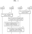
- Fig. 1 illustrates a scenario of non-compatibility between SIMs of the MUSIM UE, in accordance with prior art.
- SIM 1 (ST1) 101 also referred to herein as UE_SIM1
- SIM 2 (ST2) 105 also referred to herein as UE_SIM2
- band A and band B are compatible bands.
- the MUSIM UE is in the 1Tx/2Rx or 2Tx/2Rx mode of operation.
- SIM 2 105 reselects/is handed over to a frequency band C, or the N/W (2) 107 configures the SIM 2 105 for measurement configuration of the band C frequencies.
- the band C is incompatible with band A, so, the MUSIM UE breaks the 1Tx/2Rx or 2Tx/2Rx mode of operation and falls back to a 1Tx/1Rxmode of operation.
- Fig. 2 illustrates a scenario of non-compatibility between SIMs of the MUSIM UE due to the addition of an SCell, in accordance with prior art.
- SIM 1 (ST1) 201 is in a PS-connected mode with the first network (N/W (1)) 203 and is camped on the frequency band A.
- SIM 2 (ST2) 205 of the MUSIM UE is in idle or in connected mode with the second network (N/W (2)) 207 and is camped on the frequency band B.
- band A and band B are compatible bands. Accordingly, the MUSIM UE is in the 1Tx/2Rx or 2Tx/2Rx mode of operation.
- the first network 203 triggers a radio resource control (RRC) reconfiguration request message with Scells, which are compatible with the 1Tx/2Rx or 2Tx/2Rx mode of operation with the band A but are not compatible with the band B.
- RRC radio resource control
- the SIM 1 201 responds with an RRC reconfiguration complete message.
- the Configured SCells are compatible with band A, but not compatible with band B.
- the MUSIM UE breaks 1Tx/2Rx or 2Tx/2Rx mode and the MUSIM UE falls back to the 1Tx/1Rx mode of operation.
- frequency bands on which SIMs of the MUSIM UE are active should be compatible to avoid or reduce blackout which impacts the mobility, throughput, and call performances of the MUSIM UE.
- the present disclosure refers to a method performed by a multi-subscriber identity module (MUSIM) user equipment (UE) for continuing operation of the MUSIM UE in a first mode, the MUSIM UE including a first SIM and one or more second SIMs, and the method including transmitting, by the MUSIM UE, an uplink signalling message in response to determining a trigger condition has been satisfied, the uplink signalling message including one of compatible band information for the first SIM and the one or more second SIMs, or one or more other stacks serving band information associated with the one or more second SIMs, receiving, by the MUSIM UE from a network, a radio resource control (RRC) reconfiguration signalling message for performing at least one activity at the first SIM in response to the transmitting the uplink signalling message, and performing, by the MUSIM UE, the at least one activity based on the RRC reconfiguration signalling message.
- MUSIM multi-subscriber identity module
- UE user equipment
- a system for continuing operation of a multi-subscriber identity module (MUSIM) user equipment (UE) in a first mode the MUSIM including a first SIM and one or more second SIMs
- the system including processing circuitry configured to transmit an uplink signalling message in response to determining a trigger condition has been satisfied, the uplink signalling message including one of compatible band information for the first SIM and the one or more second SIMs, or one or more other stacks serving band information associated with the one or more second SIMs, receive, from a network, a radio resource control (RRC) reconfiguration signalling message for performing at least one activity at the first SIM in response to the transmission of the uplink signalling message, and perform the at least one activity based on the RRC reconfiguration signalling message.
- RRC radio resource control
- the present disclosure refers to a method for continuing operation of a multi-subscriber identity module (MUSIM) user equipment (MUSIM UE) in a first mode, the MUSIM UE including a first SIM and one or more second SIMs, and the method including receiving, at a network from the MUSIM UE, an uplink signalling message in response to satisfaction of a trigger condition at the MUSIM UE, the uplink signalling message including one of compatible band information for the first SIM and the one or more second SIMs, or one or more other stacks serving band information associated with the one or more second SIMs, and transmitting, from the network to the MUSIM UE, a radio resource control (RRC) reconfiguration signalling message for performing at least one activity at the first SIM in response to the uplink signalling message.
- MUSIM multi-subscriber identity module
- MUSIM UE multi-subscriber identity module
- RRC radio resource control
- a system for continuing operation of a multi-subscriber identity module (MUSIM) user equipment (MUSIM UE) in a first mode the MUSIM including a first SIM and one or more second SIMs
- the system including processing circuitry configured to receive, from the MUSIM UE, an uplink signalling message in response to satisfaction of a trigger condition at the MUSIM UE, the uplink signalling message including one of compatible band information for the first SIM and the one or more second SIMs, or one or more other stacks serving band information associated with the one or more second SIMs, and transmit, to the MUSIM UE, a radio resource control (RRC) reconfiguration signalling message for performing at least one activity at the first SIM in response to the uplink signalling message.
- RRC radio resource control
- circuits may be physically implemented by analog or digital circuits, such as logic gates, integrated circuits, microprocessors, microcontrollers, memory circuits, passive electronic components, active electronic components, optical components, hardwired circuits, or the like, and may optionally be driven by firmware and software.
- the circuits may, for example, be embodied in one or more semiconductor chips, or on substrate supports, such as printed circuit boards and the like.
- circuits constituting a block may be implemented by dedicated hardware, by a processor (e.g., one or more programmed microprocessors and associated circuitry), or by a combination of dedicated hardware to perform some functions of the block and a processor to perform other functions of the block.
- a processor e.g., one or more programmed microprocessors and associated circuitry
- Each block provided in embodiments may be physically separated into two or more interacting and discrete blocks without departing from the scope of the inventive concepts.
- the blocks provided in embodiments may be physically combined into more complex blocks without departing from the scope of the inventive concepts.
- Fig. 3 illustrates a flow chart depicting a method 300 at a multi-subscriber identity module (MUSIM) user equipment (UE) for continuing operation of the MUSIM UE in a specific mode, in accordance with embodiments of the present disclosure.
- the method as defined in reference to Fig. 3 may be performed by the MUSIM UE. As shown in Fig.
- the method may comprise indicating, by the MUSIM UE, one of: compatible band information for a first SIM and one or more second SIMs in an uplink signalling message in response to a trigger (also referred to herein as satisfaction of a trigger condition) at the MUSIM UE, or one or more other stacks serving band information associated with the one or more second SIMs of the MUSIM UE in the uplink signalling message in response to the trigger at the MUSIM UE.
- the compatible band information may be a collection of band combinations that allow the UE to receive or transmit on all configured bands at the same time (or contemporaneously) utilizing various carrier components.
- the UE may receive and transmit data at the same time (or contemporaneously) by specifying Band A in carrier component- 0 (C0) and Band B in carrier component-1 (C1).
- the compatible band information and one or more other stacks of band information facilitate in continuing operation of the MUSIM UE in the specific mode (also referred to herein as a first mode).
- the MUSIM UE comprises two SIMs, e.g., a first SIM and a second SIM.
- the MUSIM UE is currently communicating using the first SIM, wherein the first SIM is connected to a first network.
- the second SIM is connected to a second network and is either in an idle mode or in a connected mode.
- the compatible band information may include information related to compatible frequency bands associated with the first SIM and the second SIM.
- the compatible band information may include the frequency bands which are compatible to the frequency bands A and D (e.g., compatible to both frequency band A and frequency band D).
- the one or more other stacks serving band information corresponds to band information related to serving frequency bands associated with the one or more second SIMs.
- sending of one or more other stacks serving band information corresponds to sending frequency band D associated with the second SIM (e.g., the frequency band associated with the SIM not sending the one or more other stacks serving band information).
- the first SIM is communicating via a first protocol stack and the one or more second SIMs are communicating via one or more second protocol stacks.
- the protocol stacks for each of the first SIM and the one or more second SIMs are different from each other.
- the specific mode comprises a multi-transmission multi-reception mode of operation of the MUSIM UE, such as 2Tx/2Rx, 3Tx/3Rx ... MTx/NRx (where M, N>1) mode of operation.
- the specific mode may include a 1Tx/2Rx or 2Tx/2Rx mode of operation.
- the compatible band information and/or the one or more other stacks serving band information may be indicated by the MUSIM UE in an uplink signalling message sent to an associated network, such as the first network, in response to a trigger at the MUSIM UE.
- the trigger may comprise a movement of one of the first SIM and the one or more second SIMs to a connected mode or in response to detecting a change in serving band information of any of the first SIM or the one or more second SIMs, which has been further explained in reference to Figs. 4 and 5 .
- the trigger may comprise a request received from a network to obtain, from the MUSIM UE, one or more bands compatible with at least one of a carrier aggregation (CA) and/or a dual connectivity (DC) for continuing operation of the MUSIM UE in the specific mode, which has been further explained in reference to Figs. 6A-6D .
- the MUSIM UE may trigger performing a measurement report (MR) associated with an RRC reconfiguration signalling message to continue the operation of the MUSIM UE in the specific mode, wherein the measurement report comprises an optional information element (IE) indicating the specific mode preferred cell as true.
- the measurement report may be triggered by one of the following operations.
- the method 300 may include receiving, by the MUSIM UE from a network, an RRC reconfiguration signalling message for performing at least one activity at the first SIM in response to the indication of one of the compatible band information or the one or more other stacks serving band information (e.g., in response to the uplink signalling message).
- the MUSIM UE may receive the RRC reconfiguration signalling message from the first network in response to the indication transmitted at operation 301.
- the RRC reconfiguration signalling message may include information related to at least one activity (e.g., triggering measurement report, configuring the first SIM, etc.) that is to be performed by the first SIM.
- the RRC reconfiguration signalling message may comprise a plurality of measurement objects with no associated priority defined by the network, wherein the RRC reconfiguration signalling message is received for the first SIM.
- the MUSIM UE may prioritize measurement associated with one or more compatible measurement objects among the plurality of measurement objects that are compatible with serving bands of the other SIMs (e.g., the second SIM).
- the compatibility of the one or more measurement objects is determined based on the compatibility with one or more other stacks serving band information of the one or more second SIMs (and/or the compatible band information of the first SIM).
- the MUSIM UE may perform measurements for the one or more compatible measurement objects in response to determining that a cell is available and a signal strength for the available cell (e.g., with respect to one or more cells associated with the one or more compatible measurement objects) is above a predefined (or alternatively, given) measurement threshold for the one or more compatible measurement objects. However, if no band corresponding to the plurality of measurement objects is compatible with the serving bands of one or more second SIMs, or the signal strength for the available cell is not above the predefined (or alternatively, given) measurement threshold for the one or more compatible measurement objects, then the MUSIM UE may perform measurements for the one or more compatible measurement objects and/or one or more non-compatible measurements objects. This example is further explained in detail in reference to Figs.
- each of the plurality of measurement objects may represent a respective cell and a respective frequency band of the respective cell.
- the MUSIM UE may determine whether one or more cells associated with the one or more compatible measurement objects are available and whether one or more respective signal strengths corresponding to the one or more cells satisfy the predefined (or alternatively, given) measurement threshold.
- the RRC reconfiguration signalling message may comprise a conditional handover (CHO) configuration.
- the MUSIM UE may prioritize connecting to a target primary cell with a band compatible with one or more second SIMs.
- the target primary cell is defined in a list of a plurality of target cells received from the network in the RRC reconfiguration signalling message.
- the compatibility of the target cell is determined based on the compatibility with one or more other stacks serving band information of the one or more second SIMs, for continuing the specific mode of operation.
- the MUSIM UE may then trigger the RRC reconfiguration complete signalling message to the target primary cell on the compatible band, if the signal strength of the target primary cell is above the predefined (or alternatively, given) measurement threshold.
- the MUSIM UE may trigger the RRC configuration complete signalling message to one of the plurality of target cells other than the target primary cell.
- the MUSIM UE may determine whether the signal strength of the target primary cell is above the predefined (or alternatively, given) measurement threshold. This example is further explained in detail in reference to Fig. 8 .
- the method 300 may include performing, by the MUSIM UE, the at least one activity based on the RRC reconfiguration signalling message received from the network.
- the MUSIM UE through the first SIM may perform the at least one activity based on the RRC reconfiguration signalling message received from the first network at operation 303.
- performing the at least one activity based on the RRC reconfiguration signalling message may comprise configuring the first SIM, to connect with a primary cell compatible with serving bands of the first SIM and the one or more second SIMs. The compatibility of the primary cell is determined based on the compatible band information of the first SIM and/or the one or more other stacks serving band information of the one or more second SIM.
- performing the at least one activity based on the RRC reconfiguration signalling message may comprise configuring the first SIM, to connect with one or more secondary cells compatible with serving bands of the first SIM and the one or more second SIMs.
- the compatibility of the one or more secondary cells is determined based on the compatible band information of the first SIM and/or the one or more other stacks serving band information of the one or more second SIMs. This example is further explained in reference to Fig. 12 .
- performing the at least one activity based on the RRC reconfiguration signalling message may comprise configuring the first SIM, to connect with a primary cell on a secondary cell group (SCG) compatible with serving bands of the first SIM and the one or more second SIMs.
- SCG secondary cell group
- the compatibility of the primary cell is determined based on the compatible band information of the first SIM and/or the one or more other stacks serving band information of the one or more second SIMs.
- performing the at least one activity based on the RRC reconfiguration signalling message may comprise configuring the first SIM, to connect with one or more secondary cells on the SCG compatible with serving bands of the first SIM and the one or more second SIMs.
- the compatibility of the one or more secondary cells is determined based on the compatible band information of the first SIM and the one or more other stacks serving band information of the one or more second SIMs. This example is further explained in reference to Fig. 5 .
- performing the at least one activity based on the RRC reconfiguration signalling message may comprise configuring the first SIM, to measure one or more measurement objects compatible with serving bands of the one or more second SIMs, as explained in reference to Fig. 7 .
- performing the at least one activity based on the RRC reconfiguration signalling message may comprise configuring the first SIM, to measure one or more measurement objects with an associated priority, wherein the MUSIM UE is configured to trigger measurement (e.g., prioritize measurement, and trigger and/or perform measurement based on the priorities) on a first measurement object with a higher priority over measurement on a second measurement object with a lower priority.
- the first measurement object is configured with a band compatible with the one or more second SIMs and the second measurement object is configured with a band not compatible with the one or more second SIMs. This example is further explained in reference to Fig. 6C and Fig. 6D .
- performing the at least one activity based on the RRC reconfiguration signalling message may comprise configuring the first SIM with one of a higher-priority measurement object and/or a lower-priority measurement object. Thereafter, the MUSIM UE may trigger a measurement report associated with the higher-priority measurement object in response to determining an availability of a cell associated with the high-priority measurement object and determining that the measured cell (e.g., a measured signal strength of the cell) satisfies a predefined (or alternatively, given) measurement threshold.
- the measured cell e.g., a measured signal strength of the cell
- the MUSIM UE may trigger the measurement report associated with the lower-priority measurement object.
- the MUSIM UE may determine whether the cell associated with the higher-priority measurement object is available and satisfies the predefined (or alternatively, given) measurement threshold. This example is further explained in reference to Fig. 6C and FIG. 6D . Fig. 3 is further explained in reference to Figs. 4-12 below.
- the MUSIM UE may generate a communication signal (e.g., modulate, encode, etc.) and transmit the communication signal to a first cell (e.g., the cell to which the first SIM connects by the at least one activity, the cell the first SIM measures by the at least one activity and subsequently connects to (e.g., via a handover), etc.).
- a communication signal e.g., modulate, encode, etc.
- a first cell e.g., the cell to which the first SIM connects by the at least one activity, the cell the first SIM measures by the at least one activity and subsequently connects to (e.g., via a handover), etc.
- the MUSIM UE may receive communication signal from a first cell (e.g., the cell to which the first SIM connects by the at least one activity, the cell the first SIM measures by the at least one activity and subsequently connects to (e.g., via a handover), etc.) and process the received signal (e.g., decode, demodulate, etc.).
- a first cell e.g., the cell to which the first SIM connects by the at least one activity, the cell the first SIM measures by the at least one activity and subsequently connects to (e.g., via a handover), etc.
- process the received signal e.g., decode, demodulate, etc.
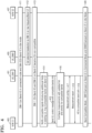
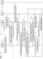
- Fig. 4 illustrates an example scenario in which an Up Link (UL) control message with compatible bands information is used to remain in the specific mode, in accordance with embodiments of the present disclosure.
- the MUSIM UE comprises two SIMs, e.g., SIM 1 (LTE_SIM1) 401 (also referred to herein as SIM1 and the first SIM) connected with a first network 403 and SIM 2 (UE_SIM2) 405 (also referred to herein as SIM2 and the second SIM) connected with a second network 407.
- SIM 1 401 is in connected mode with the first network (N/W1) 403 on a frequency band-X.
- SIM 2 405 is in idle mode with the second network (N/W2) 407 on a frequency band-Y.
- the MUSIM UE is in the specific mode of operation, e.g., 1Tx/2Rx or 2Tx/2Rx mode of operation as band-X and band-Y are CA compatible.
- SIM2 405 reselects to another frequency band-Z which is CA non-compatible with the band-X on SIM1 401. Accordingly, at operation 413, SIM1 401 and SIM2 405 become CA non-compatible. Because of the CA non-compatibility, the MUSIM UE would have fallen back to 1Tx/1Rx mode as per prior art.
- SIM1 401 which is in connected mode, indicates to the first network 403 information about its preference (and/or configuration) to operate in 1Tx/2Rx or 2Tx/2Rx mode by sending an uplink message along with the compatible band information, e.g., which bands that are supported by SIM1 401 which are compatible with band-Z, at operations 414 and 415. Accordingly, at operation 416, the first network 403 may configure the available frequency bands based on the received compatible band information for measurement on the first SIM 401.
- the compatible band information e.g., which bands that are supported by SIM1 401 which are compatible with band-Z
- the SIM1 401 may receive the RRC reconfiguration signalling message comprising the measurement configurations for the compatible bands from the first network 403. Accordingly, at operation 418, the SIM1 401 may perform the measurement for the compatible bands and may share corresponding measurement reports (MR) with the first network 403. Based on the MR, at operation 419, the first network 403 may instruct the first SIM 401 to hand over to another frequency (e.g., Band-A) which is 1Tx/2Rx or 2Tx/2Rx compatible with Band-Z. Hence, at operation 420, the MUSIM UE remains in the specific mode, e.g., 1Tx/2Rx or 2Tx/2Rx mode of operation.
- another frequency e.g., Band-A
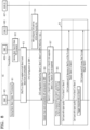
- Fig. 5 illustrates an example scenario in which a DS capability information message with compatible bands information is used to remain in the specific mode in the event of a movement of a SIM in a connected mode, in accordance with embodiments of the present disclosure.
- the MUSIM UE comprises two SIMs, e.g., SIM1 (UE_SIM1/ST1) 401 connected with a first network 403 and SIM2 (UE_SIM2/ST2) 405 connected with a second network 407.
- SIM 1 401 is in idle mode with the first network (N/W1) 403 on a frequency band A.
- SIM 2 may be in idle mode or connected mode with the second network (N/W2) 407 on a frequency band B.
- the MUSIM UE is in the specific mode of operation, e.g., 1Tx/2Rx or 2Tx/2Rx mode of operation as band A and band B are compatible with each other.
- SIM1 405 moves to (e.g., switches to, enters, etc.) connected mode.
- SIM 1 indicates compatible band information, e.g., bands compatible with band B on SIM2 via the uplink signalling message, such as a Dual SIM (DS) capability information to the first network 403. This is done to ensure future Secondary cell (Scell) or Secondary Cell Group (SCG) configurations, received from the first network 403 are compatible frequencies with band B.
- DS Dual SIM
- the first network 403 may configure a primary cell and/or one or more secondary cells from the plurality of Scells or SCG Configuration which is compatible with band B.
- SIM1 401 may receive the RRC reconfiguration signalling message with the Scell configuration or SCG Configuration, and accordingly, SIM1 may be configured with the Scells or SCG which is compatible with band B.
- SIM1 may be configured to connect with one or more secondary cells from the SCG which are compatible with band B.
- the SIM1 401 may respond with an RRC reconfiguration complete message.
- the RRC reconfiguration complete message may indicate that the SIM1 401 is connected to the Scell or SCG which is compatible with Band B.
- the MUSIM UE remains in the specific mode, e.g., 1Tx/2Rx or 2Tx/2Rx mode of operation.
- the MUSIM UE comprises two SIMs, e.g., SIM1 (UE_SIM1/ST1) 401 connected with a first network 403 and SIM2 (UE_SIM2/ST2) 405 connected with a second network 407.
- SIM 1 401 is in the PS connected mode with the first network (NAVI) 403.
- SIM 2 is in idle mode/Connected mode (e.g., idle mode or connected mode) with the second network (N/W2) 407.
- the MUSIM UE is in the specific mode of operation, e.g., 1Tx/2Rx or 2Tx/2Rx mode of operation.
- the first network 403 is aware that SIM1 401 is part of multi-SIM capable UE and configures SIM1 401 with ⁇ OtherConfig' information element (IE) in an RRC reconfiguration request message to make SIM1 indicate CA and/or dual connectivity (DC) compatible bands/band combinations to make the UE remain in the specific mode, e.g., 1Tx/2Rx or 2Tx/2Rx mode of operation.
- SIM 1 receives the RRC reconfiguration request message with the ⁇ OtherConfig' IE.
- the ⁇ OtherConfig' IE may have the following contents as shown below in Table-1 .
- the first network 403 provides a provision to the MUSIM UE to indicate one or more bands compatible with CA and/or DC to make the MUSIM UE remain in the specific mode, e.g., 1Tx/2Rx or 2Tx/2Rx mode of operation, considering the other SIM(s), e.g., SIM2 serving band/band combinations.
- SIM1 responds with the RRC reconfiguration complete message.
- SIM1 detects an occurrence of a MUSIM activity and prepares a list of BandsBand combinations that may cause the MUSIM UE to remain in the specific mode of operation.
- the MUSIM activity may include detection of a break (e.g., an anticipated break) of the specific mode or one of the SIMs moving to (e.g., switching to, entering, etc.) connected mode. Accordingly, at operation 618, SIM1 triggers a UE Assistance information message (e.g., a 3GPP US Assistance Information message) to the first network 403 with an MUSIMCompatibleBandsInformation IE.
- a UE Assistance information message e.g., a 3GPP US Assistance Information message
- the UE Assistance information message may have the following contents as shown below in Table-2 .
- SIM1 401 may send the list of CA and/or DC compatible bands/band combinations that may cause the MUSIM UE to remain in the specific mode of operation.
- the first network 403 may decide (e.g., determine) to configure (and/or may configure) SIM1 401 with band/band combinations with one of the band/band combinations from the list shared in the UE assistance information.
- the RRC reconfiguration at operation 620 may be configuring a new cell to which UE would be handed over or it could be for Scell/SCG configuration.
- SIM1 401 responds with an RRC reconfiguration complete message, and the MUSIM UE remains in the specific mode, e.g., 1Tx/2Rx or 2Tx/2Rx mode of operation.
- operations 611-621 are the same as (or similar to) operations 611-621 of Fig. 6A . Hence, a description of the same is omitted for the sake of brevity of the specification.
- SIM1 401 may not find any cell satisfying a predetermined (or alternatively, given) criteria or there may be no cells available from the compatible band list in the current location of the MUSIM UE.
- the predetermined (or alternatively, given) criteria may include measurements of the cell being less than one of a THRESHOLD_reference signal received power (RSRP), a THRESHOLD_reference signal received quality (RSRQ) and/or a THRESHOLD_signal to interference plus noise ratio (SINR), and/or a number of negative acknowledgment (NACK) in an L2 level being greater than a THRESHOLD_NACK.
- RSRP THRESHOLD_reference signal received power
- RSRQ THRESHOLD_reference signal received quality
- SINR THRESHOLD_signal to interference plus noise ratio
- NACK negative acknowledgment
- the THRESHOLD_RSRP, THRESHOLD RSRQ, THRESHOLD_SINR, and/or THRESHOLD_NACK may be defined by the network(s) associated with the MUSIM UE.
- the first network 403 may decide (e.g., determine) to configure (and/or may configure) other band cells, which may not be CA/DC compatible bands.
- the first network 403 may decide (e.g., determine) to send the reconfiguration message with measurement objects with priority information.
- compatible bands measurement objects also referred to as first measurement objects may be configured with higher-priority and other measurement objects also referred to as second measurement objects may be configured with lower-priority.
- the reconfiguration message is triggered with measurement objects with corresponding priorities, e.g., bands C and D are compatible with band B, hence they have higher-priority and band E is not compatible with band B, hence it has lower-priority.
- SIM1 401 sends RRC reconfiguration complete message to the first network 403.
- the MUSIM UE may decide to prioritize (e.g., may prioritize) the measurements for higher-priority measurement objects over low-priority measurement objects, e.g., prioritize the measurements for bands C and D over band E.
- the MUSIM UE may perform the measurement only on the higher-priority measurement objects for a specific amount of time (e.g., an amount of time defined by the UE). In embodiments, the MUSIM UE may perform the measurement on the higher-priority measurement objects only upon determining that a cell associated with the higher-priority measurement object, e.g., a cell associated with bands C or D is available and that the measured cell satisfies a predefined (or alternatively, given) measurement threshold.
- a cell associated with the higher-priority measurement object e.g., a cell associated with bands C or D is available and that the measured cell satisfies a predefined (or alternatively, given) measurement threshold.
- the predetermined (or alternatively, given) measurement threshold may include measurements of the cell being less than one of the THRESHOLD RSRP, the THRESHOLD RSRQ and/or the THRESHOLD_SINR, and/or a number of NACKs in the L2 level being greater than the THRESHOLD_NACK.
- the THRESHOLD_RSRP, THRESHOLD_RSRQ, THRESHOLD_SINR, and/or THRESHOLD_NACK may be defined by the network(s) associated with the MUSIM UE.
- the predetermined (or alternatively, given) measurement threshold may also include a predetermined (or alternatively, given) time period defined by the MUSIM UE.
- the MUSIM UE may trigger the measurement report associated with the lower-priority measurement object, e.g., band E.
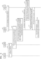
- Fig. 7 illustrates a scenario of retaining the specific mode by prioritizing measurement reports for compatible bands, in accordance with embodiments of the present disclosure.
- Operation 710 is a precondition that is explained with reference to operations 712-714 (e.g., operation 710 may refer to the precondition represented by operations 712-714).
- SIM1 401 is in PS connected state on a serving band A with a first network 403.
- SIM2 405 is either in idle mode or the PS connected state on a serving band B with a second network 407.
- Serving band, A on SIM1 401 is CA compatible with serving band B on SIM2, and hence simultaneous (or contemporaneous) Tx/Rx operation is possible.
- the MUSIM UE is operating in the specific mode, e.g., 2Tx/2Rx or 1Tx/2Rx mode.
- Operation 715 defines measurement reporting on SIM1 401, which is explained with reference to operations 716-729 (e.g., operation 715 may refer to the precondition represented by operations 716-729).
- the first network 403 configures inter-frequency measurements on bands C, D, and E by sending the RRC reconfiguration message to SIM1 401 at operation 717.
- the bands C and D are CA compatible with band B, whereas band E is not CA compatible with band B.
- SIM1 401 sends the RRC reconfiguration complete message.
- the MUSIM UE on SIM1 401 evaluates band compatibility between these inter-frequency bands on SIM1 401 with a serving band on SIM2.
- the MUSIM UE determines that bands C and D are CA compatible with serving band B of SIM2 405, whereas band E is not CA compatible with serving band B of SIM2 405.
- the MUSIM UE on SIM1 401 prioritizes measurements on one or more measurement objects compatible with bands A and B, such as measurement objects of bands C and D as they are CA compatible with the SIM2 Serving band. This happens along with simultaneous (or contemporaneous) Tx/Rx operation on SIM2.
- the MUSIM UE is still in the specific mode of operation.
- the MUSIM UE may perform the measurement on compatible bands C and/or D only upon determining that a cell associated with the compatible band C and/or D is available and that the measured cell satisfies a predefined (or alternatively, given) measurement threshold.
- the predetermined (or alternatively, given) measurement threshold may include measurements of the cell being less than one of the THRESHOLD RSRP, THRESHOLD RSRQ, and/or THRESHOLD_SINR.
- the predetermined (or alternatively, given) measurement threshold may be determined by the UE or predefined (or alternatively, given) by the UE.
- the predetermined (or alternatively, given) measurement threshold may also include a predetermined (or alternatively, given) time period defined by the MUSIM UE.
- the MUSIM UE may trigger the measurement report associated with the non-compatible band E. For example, as shown in Fig. 7 , at operation 722, the MUSIM UE determines that the cell associated with compatible band C or D has a measurement threshold greater than the predetermined (or alternatively, given) measurement threshold.
- Tx/Rx operation with inter-frequency measurements on SIM1 401 and Tx/Rx operation on SIM2 405 happens simultaneously (or contemporaneously).
- SIM1 401 sends MR of compatible band C and/or D to the first network 403.
- Tx/Rx operation is stopped on SIM2 405.
- the MUSIM UE triggers measurement reporting associated with the non-compatible band E.
- SIM1 401 sends an MR of band E to the first network 403.
- Tx/Rx operation is resumed on SIM2 405.
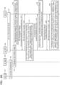
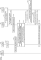
- Fig. 8 illustrates a scenario of retaining the specific mode in case of a conditional handover (CHO), in accordance with embodiments of the present disclosure.
- the MUSIM UE comprises two SIMs, e.g., SIM1 (UE_SIM1) 401 connected with a first network 403 and SIM2 (UE_SIM2) 405 connected with a second network 407.
- SIM 1 401 is in PS connected mode with the first network (N/W1) 403 on a frequency band A.
- SIM 2 405 is also in connected mode with the second network (N/W2) 407 on a frequency band B at operation 812.
- the MUSIM UE is in the specific mode of operation, e.g., 1Tx/2Rx or 2Tx/2Rx mode of operation as band A and band B are CA compatible.
- the first network 403 configures (e.g., determines) the CHO configuration with (e.g., to correspond to) cells from bands C, D, and E with measurement and reconfiguration information.
- the bands C and D are CA compatible with band B, whereas band E is not CA compatible with band B.
- the MUSIM UE may receive the RRC reconfiguration signalling message comprising the configuration for the CHO handover.
- the RRC reconfiguration signalling message may also include a list of a plurality of target cells for the CHO.
- the list of the plurality of target cells may also define one or more target primary cells where the defined one or more target primary cells are compatible with the SIM2 405.
- the list may identify cells associated with bands C, D, and E as target primary cells.
- SIM1 401 performs the measurement for the CHO configuration.
- the SIM1 401 may determine that bands C and D are CA-compatible, whereas band E is not CA-compatible.
- SIM1 401 prioritizes measurement and CHO on bands C and D as these bands are CA compatible, as shown at operation 819.
- SIM1 401 may perform the CHO on bands C and/or D only upon determining that a signal strength of the target primary cell, e.g., a cell associated with the compatible band C and/or D is above the predefined (or alternatively, given) measurement threshold. However, if SIM1 401 determines that the signal strength of the target primary cell is below the predefined (or alternatively, given) measurement threshold, then SIM1 may trigger measurement on cell(s) other than the target primary cell, such as a cell associated with band E, and may complete the CHO on band E.
- a signal strength of the target primary cell e.g., a cell associated with the compatible band C and/or D is above the predefined (or alternatively, given) measurement threshold.
- SIM1 may trigger measurement on cell(s) other than the target primary cell, such as a cell associated with band E, and may complete the CHO on band E.
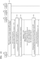
- Fig. 9 illustrates an example scenario in which a measurement report with one or more stacks serving band information is used to remain in the specific mode in case of a handover (HO), in accordance with embodiments of the present disclosure.
- SIM1 401 is connected with a first network 403 and is camped on a band B1.
- SIM2 405 is connected with a second network 407 and is camped on a band B2.
- B1 and B2 are not compatible bands.
- the first network 403 is monitoring acknowledgment (ACK)/ NACK and signal strength of the SIM1 401, e.g., determining whether the signal strength is above the predetermined (or alternatively, given) measurement threshold and the number of NACKs is greater than the THRESHOLD_NACK. If yes, then at operation 913, the first network 403 determines that the signal conditions of SIM1 401 are good.
- the first network 403 suspects that the MUSIM UE is operating in dual-SIM dual-standby (DSDS) mode and accordingly requests for UE information to know the DSDS status of the MUSIM UE.
- the UE information may be requested by the networks in a downlink signalling message.
- the networks may request the UE information to know about (e.g., determine) the dual SIM capability of the UE.
- the networks may trigger the UE.
- SIM1 401 responds with the UE information, by utilizing the dual SIM capability, with DSDS status as true.
- the first network 403 finds that DSDS is enabled at the MUSIM LTE.
- the first network 403 sends the RRC reconfiguration message with Measurement object and OtherStackEnquiry, the network may use these elements (e.g., Measurement object and OtherStackEnquiry) to request that the UE provide its other stack's band information. In this message, the first network 403 may enquire about the other stack serving band information.
- the MUSIM UE sends the RRC reconfiguration complete message.
- the MUSIM UE sends a measurement report which contains the OtherStackEnquiry result. With OtherStackEnquiry result, the first network 403 may know about (e.g., determine) the camping frequency band of one or more other stacks, e.g., SIM2 405.
- the first network 403 determines if any cell is available of band B2 which is compatible with the band of the one or more other stacks, or if any cell is available which is compatible with the band of one or more other stacks. Accordingly, at operation 919, the first network 403 sends the RRCConnectionReconfiguration for the mobility info which contains the compatible band information including a primary cell associated with the compatible band for handover.
- the MUSIM UE sends the RRC reconfiguration complete message.
- the MUSIM UE triggers the handover at the primary cell associated with the compatible band, e.g., SIM1 401 is configured to connect with the primary cell. Accordingly, SIM1 401 and SIM2 405 are connected to compatible bands and may work together to improve the performance of the MUSIM UE.
- Figs 10-11 illustrate various scenarios which indicate preferred band information is included in the measurement report along with one or more existing results to remain in the specific mode in case of a HO, in accordance with embodiments of the present disclosure.
- SIM1 401 is connected with a first network 403 on a band-X and SIM2 405 is connected with a second network 407 on a band-Y.
- the MUSIM UE is in the specific mode of operation, e.g., 1Tx/2Rx or 2Tx/2Rx mode of operation as band-X and band-Y are compatible with each other.
- SIM1 401 receives a RRC connection reconfiguration message to perform measurement associated with band A and band B.
- SIM1 401 identifies band A as being 1Tx/2Rx or 2Tx/2Rx compatible with frequency on SIM2 405.
- SIM1 401 prioritizes the measurement of band A over band B and also indicates to the first network 403 that band A is a 1Tx/2Rx or 2Tx/2Rx preferred band (as used herein, an indication of a preferred band may refer to a compatible band and/or a prioritized band) for any mobility, e.g., indicates the compatible band information, which is defined in operation 1015.
- SIM 1 401 performs measurement for the serving band, e.g., band X and prioritizes measurement for band A over band B.
- SIM1 401 also determines that band A is a 1Tx/2Rx or 2Tx/2Rx preferred band, and hence is a compatible band to continue the specific mode of operation.
- the first network 403 evaluates the measurement result and gives preference (e.g., priority) to the band A frequency for mobility (HO), so that 1Tx/2Rx or 2Tx/2Rx compatibility is maintained at the MUSIM UE side. Accordingly, at operation 1017, the first network 403 sends the RRC reconfiguration signalling message, such as the RRC connection reconfiguration message instructing the MUSIM UE to perform handover to a cell associated with band A. Accordingly, SIM1 401 is configured to connect to the primary cell from Band A, So SIM1 and SIM 2 remain in CA-compatible bands, and 1Tx/2Rx or 2Tx/2Rx mode is maintained.
- the RRC reconfiguration signalling message such as the RRC connection reconfiguration message instructing the MUSIM UE to perform handover to a cell associated with band A.
- SIM1 401 is configured to connect to the primary cell from Band A, So SIM1 and SIM 2 remain in CA-compatible bands, and 1Tx/2Rx or 2Tx/2Rx mode is maintained.
- SIM1 401 UE identifies that none of the measured frequencies, e.g., cells are compatible with the frequency on SIM2 405, e.g., none of the bands A and B are compatible with band Y.
- SIM1 401 performs measurement for the serving band X and bands A and B.
- SIM1 401 also determines that none of the bands A and B is a 1Tx/2Rx or 2Tx/2Rx preferred band.
- the first network 403 evaluates the measurement results and performs handover (HO) to the 1Tx/2Rx or 2Tx/2Rx non-compatible band to give more preference (e.g., greater priority) to mobility.
- the first network 403 evaluates the measurement results and determines that the signal strength of a cell associated with band A is greater than the signal strength of a cell associated with band B. Accordingly, the first network 403 determines to perform HO on band A. Therefore, at operation 1116, the first network 403 sends the RRC reconfiguration signalling message, such as the RRC connection reconfiguration message instructing the MUSIM UE to perform handover to a cell associated with band A, e.g., a primary cell.
- the RRC reconfiguration signalling message such as the RRC connection reconfiguration message instructing the MUSIM UE to perform handover to a cell associated with band A, e.g., a primary cell.
- Fig. 12 illustrates a scenario of retaining the specific mode in the event of a Scell addition, in accordance with embodiments of the present disclosure.
- the MUSIM UE comprises two SIMs, e.g., SIM1 (UE_SIM1) 401 connected with a first network 403 and SIM2 (UE_SIM2) 405 connected with a second network 407.
- SIM 1 401 is in PS-connected mode with the first network (NAVI) 403 on a frequency band A.
- SIM2 405 is powered OFF.
- the first network 403 configures a secondary cell (Scell) on band D and sends RRC Reconfiguration Request to SIM1 401.
- Scell secondary cell
- SIM1 401 determines that band D is a compatible band (e.g., compatible with band A).
- SIM2 405 is powered on and camps on band B.
- band B is compatible with band A, but not with band D, and SIM1 would not be able to operate in the specific mode of operation, e.g., 1Tx/2Rx or 2Tx/2Rx mode of operation.
- a break in the specific mode is detected (e.g., an anticipated break in the specific mode is detected) and SIM1 401 triggers DS capability information to indicate the compatible bands with band B on SIM2 405 at operation 1218.
- the first network 403 configures a Scell associated with a compatible band, such as band C, from the list of compatible bands received in the DS capability information.
- SIM1 401 receives the RRC reconfiguration signalling message, such as RRC Reconfiguration from the first network 403.
- the RRC reconfiguration signalling message may contain an instruction to remove the Scell on band D and add Scell on the compatible band, e.g., band C which is compatible with band B of SIM2 405, and Band A which is the primary cell in SIM 1 401.
- SIM1 401 responds with an RRC Reconfiguration complete message indicating that SIM1 401 is configured to connect to the Scell on band C.
- the MUSIM UE remains in the specific mode of operation.
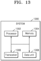
- Fig. 13 illustrates a block diagram of a system 1300 for continuing operation of the MUSIM UE in the specific mode, in accordance with embodiments of the present disclosure.
- the system 1300 may be a part of the MUSIM UE.
- the system 1300 may be connected to the MUSIM UE.
- the system 1300 may include but is not limited to, a processor 1302, a memory 1304, a transceiver 1306, and/or a data unit 1308.
- the memory 1304 and the transceiver 1306 may be coupled to the processor 1302.
- the system 1300 may be configured to perform methods as discussed in reference to Figs. 3-12 .
- the processor 1302 may be configured to transmit the indication of the compatible band information and the one or more other stacks serving band information via the transceiver 1306.
- the processor 1302 may be configured to receive the RRC reconfiguration signalling message via the transceiver 1306.
- operations described herein as being performed by SIM1 401 and/or SIM2 405 may be performed by the processor 1302.
- operations described herein as being performed by the MUSIM UE may be performed by the processor 1302.
- the system 1300 and/or the MUSIM UE may be fixed or mobile and may refer to any device that may communicate with a base station (e.g., the first network 403 and/or the second network 407) to transmit and receive data and/or control information.
- a base station e.g., the first network 403 and/or the second network 407
- the system 1300 and/or the MUSIM UE may refer to a terminal, a terminal equipment, a mobile station (MS), a mobile terminal (MT), a user terminal (UT), a subscriber station (SS), a wireless device, a handheld device, or the like.
- the processor 1302 may be a single processing unit or several units, all of which could include multiple computing units.
- the processor 1302 may be implemented as one or more microprocessors, microcomputers, microcontrollers, digital signal processors, central processing units, state machines, logic circuitries, and/or any MUSIM UEs that manipulate signals based on operational instructions.
- the processor 1302 is configured to fetch and execute computer-readable instructions and data stored in the memory 1304, respectively.
- the memory 1304 may include any non-transitory computer-readable medium known in the art including, for example, volatile memory, such as static random-access memory (SRAM) and dynamic random-access memory (DRAM), and/or non-volatile memory, such as read-only memory (ROM), erasable programmable ROM, flash memories, hard disks, optical disks, and magnetic tapes.
- volatile memory such as static random-access memory (SRAM) and dynamic random-access memory (DRAM)
- DRAM dynamic random-access memory
- non-volatile memory such as read-only memory (ROM), erasable programmable ROM, flash memories, hard disks, optical disks, and magnetic tapes.
- the data unit 1308 serves, amongst other things, as a repository for storing data processed, received, and generated by the processor 1302.
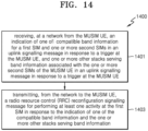
- Fig. 14 illustrates a flow chart depicting a method 1400 for continuing operation of the MUSIM UE in the specific mode, in accordance with embodiments of the present disclosure. It should be noted that the method as described in reference to Fig. 14 may be performed by a network associated with the MUSIM UE. In embodiments, the MUSIM UE may comprise two SIMs, e.g., a first SIM connected with a first network and a second SIM connected with a second network. If the MUSIM UE is currently communicating via the first SIM, then the method of Fig. 14 may be performed by the first network. Referring back to Fig. 14 , as shown in Fig.
- the method 1400 may include receiving from the MUSIM UE, an indication of one of: compatible band information for a first SIM and one or more second SIMs in an uplink signalling message in response to a trigger at the MUSIM UE, and one or more other stacks serving band information associated with the one or more second SIMs of the MUSIM UE in an uplink signalling message in response to a trigger at the MUSIM UE.
- the compatible band information and the one or more other stacks band information facilitate in continuing operation of the MUSIM UE in the specific mode.
- the indication may be received analogues to the techniques as discussed in reference to operation 301.
- the method 1400 includes determining a behaviour of network when the measurement report with priority information or band preferred information is shared.
- the method 1400 may include transmitting to the MUSIM UE, the RRC reconfiguration signalling message for performing at least one activity at the first SIM in response to the indication of one of the compatible band information and the one or more other stacks serving band information.
- the RRC reconfiguration signalling message is already explained in reference to Fig. 3 and hence, the description of the same is omitted here for the sake of brevity of the description.
- Fig. 15 illustrates a block diagram of a system 1500 for continuing operation of the MUSIM UE in the specific mode, in accordance with embodiments of the present disclosure.
- the system 1500 may be a part of the network associated with the MUSIM UE.
- the system 1500 may be connected to the network.
- the system 1500 may include but is not limited to, a processor 1502, a memory 1504, a transceiver 1506, and/or a data unit 1508.
- the memory 1504 and the transceiver 1506 may be coupled to the processor 1502.
- the system 1500 may be configured to perform methods as discussed in reference to Fig. 14 .
- the processor 1502 may be configured to receive the indication of the compatible band information and the one or more other stacks serving band information via the transceiver 1506.
- the processor 1502 may be configured to transmit the RRC reconfiguration signalling message via the transceiver 1506.
- the system 1500, the first network 403 and/or the second network 407 may be implemented by a respective base station.
- a base station may generally refer to a fixed station that communicates with user equipment and/or other base stations, and may exchange data and control information by communicating with user equipment and/or other base stations.
- the base station may refer to a Node B, an evolved-Node B (eNB), a next generation Node B (gNB), a sector, a site, a base transceiver system (BTS), an access point (AP), a relay node, a remote radio head (RRH), a radio unit (RU), a small cell, or the like.
- eNB evolved-Node B
- gNB next generation Node B
- AP access point
- RRH remote radio head
- RU radio unit
- a base station or a cell may be interpreted in a comprehensive sense to indicate some area or function covered by a base station controller (BSC) in Code Division Multiple Access (CDMA), a Node-B in wideband CDMA (WCDMA), an eNB in long-term evolution (LTE), a gNB or sector (site) in 5G, and the like, and may cover all the various coverage areas such as megacell, macrocell, microcell, picocell, femtocell and relay node, RRH, RU, and small cell communication range.
- BSC base station controller
- CDMA Code Division Multiple Access
- WCDMA wideband CDMA
- LTE long-term evolution
- gNB or sector site in 5G, and the like
- a wireless communication network between the MUSIM UE (e.g., the system 1300) and the base station (e.g., the system 1500, the first network 403 and/or the second network 407) may support communication between multiple users by sharing available network resources.
- information may be transmitted in various multiple access schemes, such as CDMA, Frequency Division Multiple Access (FDMA), Time Division Multiple Access (TDMA), Orthogonal Frequency Division Multiple Access (OFDMA), Single Carrier Frequency Division Multiple Access (SC-FDMA), OFDM-FDMA, OFDM-TDMA, and OFDM-CDMA.
- CDMA Code Division Multiple Access
- FDMA Frequency Division Multiple Access
- TDMA Time Division Multiple Access
- OFDMA Orthogonal Frequency Division Multiple Access
- SC-FDMA Single Carrier Frequency Division Multiple Access
- OFDM-FDMA OFDM-FDMA
- OFDM-TDMA OFDM-TDMA
- OFDM-CDMA OFDM-CDMA
- the processor 1502 may be a single processing unit or several units, all of which could include multiple computing units.
- the processor 1502 may be implemented as one or more microprocessors, microcomputers, microcontrollers, digital signal processors, central processing units, state machines, logic circuitries, and/or any MUSIM UEs that manipulate signals based on operational instructions.
- the processor 1502 is configured to fetch and execute computer-readable instructions and data stored in the memory 1504, respectively.
- the memory 1504 may include any non-transitory computer-readable medium known in the art including, for example, volatile memory, such as static random-access memory (SRAM) and dynamic random-access memory (DRAM), and/or non-volatile memory, such as read-only memory (ROM), erasable programmable ROM, flash memories, hard disks, optical disks, and magnetic tapes.
- volatile memory such as static random-access memory (SRAM) and dynamic random-access memory (DRAM)
- DRAM dynamic random-access memory
- non-volatile memory such as read-only memory (ROM), erasable programmable ROM, flash memories, hard disks, optical disks, and magnetic tapes.
- the data unit 1508 serves, amongst other things, as a repository for storing data processed, received, and generated by the processor 1502.
- the present disclosure discloses the techniques which allow the MUSIM UE to remain in MTx/NRx mode of operation by making the network configure only compatible bands considering serving band information of all the SIMs associated with the MUSIM UE. This way the MUSIM UE may provide improved services to a user and the MUSIM UE without falling back to a 1Tx/1Rx mode of operation because the MUSIM UE may operate in the MTx/NRx mode of operation.
- Conventional devices and methods for performing simultaneous or contemporaneous communication through a plurality of SIMs fail to operate in the first mode with sufficient consistency.
- the conventional devices and methods excessively connect one of the plurality of SIMs to a cell operating at a frequency that is incompatible with that of another of the plurality of SIMs, such that the conventional devices and methods are unable to communicate in the first mode.
- the plurality of SIMs communicate alternatingly such that an overall bandwidth of the conventional devices and methods is reduced, and a communication delay of the conventional devices and methods is increased.
- improved devices and methods are provided for performing communication in the first mode.
- the improved devices and methods may initiate connections between a first SIM among the plurality of SIMs with a cell based on whether an operating frequency of the cell is compatible with a frequency of one or more second SIMs among the plurality of SIMs.
- the improved devices and methods reduce a frequency of occurrence in which the first SIM connects to a cell operating at a frequency that is incompatible with that of the one or more second SIMs, thereby enabling the improved devices and methods to communicate in the first mode more consistently than is the case with the conventional devices and methods.
- the improved devices and methods overcome the deficiencies of the conventional devices and methods to at least increase bandwidth and decrease communication delay.
- operations described herein as being performed by the SIM 1 101, the first network 103, the SIM 2 105, the second network 107, the SIM 1 201, the first network 203, the SIM 2 205, the second network 207, the SIM1 401, the first network 403, the SIM2 405, the second network 407, the system 1300, the processor 1302, the transceiver 1306, the system 1500, the processor 1502, and/or the transceiver 1506 may be performed by processing circuitry.
- processing circuitry may refer to, for example, hardware including logic circuits; a hardware/software combination such as a processor executing software; or a combination thereof.
- the processing circuitry more specifically may include, but is not limited to, a central processing unit (CPU), an arithmetic logic unit (ALU), a digital signal processor, a microcomputer, a field programmable gate array (FPGA), a System-on-Chip (SoC), a programmable logic unit, a microprocessor, application-specific integrated circuit (ASIC), etc.
- CPU central processing unit
- ALU arithmetic logic unit
- DSP digital signal processor
- microcomputer a field programmable gate array
- FPGA field programmable gate array
- SoC System-on-Chip
- ASIC application-specific integrated circuit
- the various operations of methods described above may be performed by any suitable device capable of performing the operations, such as the processing circuitry discussed above.
- the operations of methods described above may be performed by various hardware and/or software implemented in some form of hardware (e.g., processor, ASIC, etc.).
- the software may comprise an ordered listing of executable instructions for implementing logical functions, and may be embodied in any "processor-readable medium" for use by or in connection with an instruction execution system, apparatus, or device, such as a single or multiple-core processor or processor-containing system.
- a software module may reside in Random Access Memory (RAM), flash memory, Read Only Memory (ROM), Electrically Programmable ROM (EPROM), Electrically Erasable Programmable ROM (EEPROM), registers, hard disk, a removable disk, a CD ROM, or any other form of storage medium known in the art.
- RAM Random Access Memory
- ROM Read Only Memory
- EPROM Electrically Programmable ROM
- EEPROM Electrically Erasable Programmable ROM
- Embodiments may be described with reference to acts and symbolic representations of operations (e.g., in the form of flow charts, flow diagrams, data flow diagrams, structure diagrams, block diagrams, etc.) that may be implemented in conjunction with units and/or devices discussed in more detail herein.
- a function or operation specified in a specific block may be performed differently from the flow specified in a flowchart, flow diagram, etc.
- functions or operations illustrated as being performed serially in two consecutive blocks may actually be performed concurrently, simultaneously, contemporaneously, or in some cases be performed in reverse order.
Landscapes
- Engineering & Computer Science (AREA)
- Signal Processing (AREA)
- Computer Networks & Wireless Communication (AREA)
- Databases & Information Systems (AREA)
- Quality & Reliability (AREA)
- Physics & Mathematics (AREA)
- Electromagnetism (AREA)
- Mobile Radio Communication Systems (AREA)
Applications Claiming Priority (1)
| Application Number | Priority Date | Filing Date | Title |
|---|---|---|---|
| IN202241051463 | 2022-09-08 |
Publications (1)
| Publication Number | Publication Date |
|---|---|
| EP4340417A1 true EP4340417A1 (fr) | 2024-03-20 |
Family
ID=87971859
Family Applications (1)
| Application Number | Title | Priority Date | Filing Date |
|---|---|---|---|
| EP23195938.8A Pending EP4340417A1 (fr) | 2022-09-08 | 2023-09-07 | Procédés et systèmes pour poursuivre un ue musim en mode spécifique |
Country Status (4)
| Country | Link |
|---|---|
| US (1) | US20240098480A1 (fr) |
| EP (1) | EP4340417A1 (fr) |
| KR (1) | KR20240035373A (fr) |
| CN (1) | CN117676876A (fr) |
Citations (2)
| Publication number | Priority date | Publication date | Assignee | Title |
|---|---|---|---|---|
| WO2021148192A1 (fr) * | 2020-01-21 | 2021-07-29 | Nokia Technologies Oy | Attribution de porteuses dans un réseau sans fil |
| EP4040913A1 (fr) * | 2019-10-31 | 2022-08-10 | Huawei Technologies Co., Ltd. | Procédé, dispositif et système de communication |
-
2023
- 2023-09-07 US US18/462,662 patent/US20240098480A1/en active Pending
- 2023-09-07 EP EP23195938.8A patent/EP4340417A1/fr active Pending
- 2023-09-08 KR KR1020230119815A patent/KR20240035373A/ko active Pending
- 2023-09-08 CN CN202311160521.9A patent/CN117676876A/zh active Pending
Patent Citations (2)
| Publication number | Priority date | Publication date | Assignee | Title |
|---|---|---|---|---|
| EP4040913A1 (fr) * | 2019-10-31 | 2022-08-10 | Huawei Technologies Co., Ltd. | Procédé, dispositif et système de communication |
| WO2021148192A1 (fr) * | 2020-01-21 | 2021-07-29 | Nokia Technologies Oy | Attribution de porteuses dans un réseau sans fil |
Also Published As
| Publication number | Publication date |
|---|---|
| CN117676876A (zh) | 2024-03-08 |
| KR20240035373A (ko) | 2024-03-15 |
| US20240098480A1 (en) | 2024-03-21 |
Similar Documents
| Publication | Publication Date | Title |
|---|---|---|
| US8724545B2 (en) | Method and apparatus to facilitate support for multi-radio coexistence | |
| US10064082B2 (en) | Method and apparatus for limiting transmission of in-device coexistence indication message in wireless communication system | |
| US9832778B2 (en) | In-device coexistence interference in a communications network | |
| US8995359B2 (en) | Method and apparatus to facilitate support for multi-radio coexistence | |
| CN107710863B (zh) | 通过双天线共享在共享频带上的共存 | |
| KR101473815B1 (ko) | 다중-라디오 공존을 위한 방법 및 장치 | |
| US9686740B2 (en) | Systems and methods for intelligent frequency selection in carrier aggregation enabled networks | |
| CN112203355A (zh) | 基于无执照频谱上的lte中的信号强度测量的rrm | |
| EP3930367B1 (fr) | Procédé et appareil de commande de mesure, terminal et dispositif de réseau | |
| US20180092007A1 (en) | Dynamic RAT Selection | |
| US20150099523A1 (en) | Inter-radio access technology (irat) measurement during handover | |
| CN113141652B (zh) | 在测量时隙内收发信号的方法、网元设备及可读存储介质 | |
| EP3669568B1 (fr) | Commande de distribution de trafic pour réseaux d'accès hybrides sans fil | |
| CN112789895A (zh) | 一种切换方法及装置、终端、网络设备 | |
| EP2941087B1 (fr) | Procédé, appareil, et dispositif de communication à porteuses multiples | |
| WO2020154871A1 (fr) | Procédé de commande de mesure, dispositif terminal, et dispositif de réseau | |
| US11523397B2 (en) | Information transmission method, network device, and terminal device | |
| EP4340417A1 (fr) | Procédés et systèmes pour poursuivre un ue musim en mode spécifique | |
| US20250106836A1 (en) | Dynamic serving cell configuration | |
| US20240205714A1 (en) | Method for measurement relaxation and communication device | |
| US20200137600A1 (en) | Measurements and signalling for fast setup | |
| CN104349377A (zh) | 一种实现ue测量的方法和设备 |
Legal Events
| Date | Code | Title | Description |
|---|---|---|---|
| PUAI | Public reference made under article 153(3) epc to a published international application that has entered the european phase |
Free format text: ORIGINAL CODE: 0009012 |
|
| STAA | Information on the status of an ep patent application or granted ep patent |
Free format text: STATUS: THE APPLICATION HAS BEEN PUBLISHED |
|
| AK | Designated contracting states |
Kind code of ref document: A1 Designated state(s): AL AT BE BG CH CY CZ DE DK EE ES FI FR GB GR HR HU IE IS IT LI LT LU LV MC ME MK MT NL NO PL PT RO RS SE SI SK SM TR |
|
| P01 | Opt-out of the competence of the unified patent court (upc) registered |
Free format text: CASE NUMBER: APP_34409/2024 Effective date: 20240607 |
|
| STAA | Information on the status of an ep patent application or granted ep patent |
Free format text: STATUS: REQUEST FOR EXAMINATION WAS MADE |
|
| 17P | Request for examination filed |
Effective date: 20240919 |
|
| RBV | Designated contracting states (corrected) |
Designated state(s): AL AT BE BG CH CY CZ DE DK EE ES FI FR GB GR HR HU IE IS IT LI LT LU LV MC ME MK MT NL NO PL PT RO RS SE SI SK SM TR |