EP4342013B1 - Behandlung wasserstoffhaltiger und sauerstoffhaltiger restgase von brennstoffzellen - Google Patents
Behandlung wasserstoffhaltiger und sauerstoffhaltiger restgase von brennstoffzellen Download PDFInfo
- Publication number
- EP4342013B1 EP4342013B1 EP22750781.1A EP22750781A EP4342013B1 EP 4342013 B1 EP4342013 B1 EP 4342013B1 EP 22750781 A EP22750781 A EP 22750781A EP 4342013 B1 EP4342013 B1 EP 4342013B1
- Authority
- EP
- European Patent Office
- Prior art keywords
- fuel cell
- recombination
- fuel
- fuel cells
- hydrogen
- Prior art date
- Legal status (The legal status is an assumption and is not a legal conclusion. Google has not performed a legal analysis and makes no representation as to the accuracy of the status listed.)
- Active
Links
Images


Classifications
-
- H—ELECTRICITY
- H01—ELECTRIC ELEMENTS
- H01M—PROCESSES OR MEANS, e.g. BATTERIES, FOR THE DIRECT CONVERSION OF CHEMICAL ENERGY INTO ELECTRICAL ENERGY
- H01M8/00—Fuel cells; Manufacture thereof
- H01M8/06—Combination of fuel cells with means for production of reactants or for treatment of residues
- H01M8/0662—Treatment of gaseous reactants or gaseous residues, e.g. cleaning
-
- H—ELECTRICITY
- H01—ELECTRIC ELEMENTS
- H01M—PROCESSES OR MEANS, e.g. BATTERIES, FOR THE DIRECT CONVERSION OF CHEMICAL ENERGY INTO ELECTRICAL ENERGY
- H01M8/00—Fuel cells; Manufacture thereof
- H01M8/02—Details
- H01M8/0202—Collectors; Separators, e.g. bipolar separators; Interconnectors
- H01M8/0204—Non-porous and characterised by the material
- H01M8/0206—Metals or alloys
-
- H—ELECTRICITY
- H01—ELECTRIC ELEMENTS
- H01M—PROCESSES OR MEANS, e.g. BATTERIES, FOR THE DIRECT CONVERSION OF CHEMICAL ENERGY INTO ELECTRICAL ENERGY
- H01M8/00—Fuel cells; Manufacture thereof
- H01M8/04—Auxiliary arrangements, e.g. for control of pressure or for circulation of fluids
- H01M8/04298—Processes for controlling fuel cells or fuel cell systems
- H01M8/04313—Processes for controlling fuel cells or fuel cell systems characterised by the detection or assessment of variables; characterised by the detection or assessment of failure or abnormal function
- H01M8/04537—Electric variables
- H01M8/04544—Voltage
- H01M8/04559—Voltage of fuel cell stacks
-
- H—ELECTRICITY
- H01—ELECTRIC ELEMENTS
- H01M—PROCESSES OR MEANS, e.g. BATTERIES, FOR THE DIRECT CONVERSION OF CHEMICAL ENERGY INTO ELECTRICAL ENERGY
- H01M8/00—Fuel cells; Manufacture thereof
- H01M8/04—Auxiliary arrangements, e.g. for control of pressure or for circulation of fluids
- H01M8/04298—Processes for controlling fuel cells or fuel cell systems
- H01M8/04313—Processes for controlling fuel cells or fuel cell systems characterised by the detection or assessment of variables; characterised by the detection or assessment of failure or abnormal function
- H01M8/04537—Electric variables
- H01M8/04544—Voltage
- H01M8/04567—Voltage of auxiliary devices, e.g. batteries, capacitors
-
- H—ELECTRICITY
- H01—ELECTRIC ELEMENTS
- H01M—PROCESSES OR MEANS, e.g. BATTERIES, FOR THE DIRECT CONVERSION OF CHEMICAL ENERGY INTO ELECTRICAL ENERGY
- H01M8/00—Fuel cells; Manufacture thereof
- H01M8/04—Auxiliary arrangements, e.g. for control of pressure or for circulation of fluids
- H01M8/04298—Processes for controlling fuel cells or fuel cell systems
- H01M8/04313—Processes for controlling fuel cells or fuel cell systems characterised by the detection or assessment of variables; characterised by the detection or assessment of failure or abnormal function
- H01M8/04537—Electric variables
- H01M8/04574—Current
- H01M8/04589—Current of fuel cell stacks
-
- H—ELECTRICITY
- H01—ELECTRIC ELEMENTS
- H01M—PROCESSES OR MEANS, e.g. BATTERIES, FOR THE DIRECT CONVERSION OF CHEMICAL ENERGY INTO ELECTRICAL ENERGY
- H01M8/00—Fuel cells; Manufacture thereof
- H01M8/04—Auxiliary arrangements, e.g. for control of pressure or for circulation of fluids
- H01M8/04298—Processes for controlling fuel cells or fuel cell systems
- H01M8/04313—Processes for controlling fuel cells or fuel cell systems characterised by the detection or assessment of variables; characterised by the detection or assessment of failure or abnormal function
- H01M8/04537—Electric variables
- H01M8/04574—Current
- H01M8/04597—Current of auxiliary devices, e.g. batteries, capacitors
-
- H—ELECTRICITY
- H01—ELECTRIC ELEMENTS
- H01M—PROCESSES OR MEANS, e.g. BATTERIES, FOR THE DIRECT CONVERSION OF CHEMICAL ENERGY INTO ELECTRICAL ENERGY
- H01M8/00—Fuel cells; Manufacture thereof
- H01M8/24—Grouping of fuel cells, e.g. stacking of fuel cells
- H01M8/249—Grouping of fuel cells, e.g. stacking of fuel cells comprising two or more groupings of fuel cells, e.g. modular assemblies
-
- H—ELECTRICITY
- H01—ELECTRIC ELEMENTS
- H01M—PROCESSES OR MEANS, e.g. BATTERIES, FOR THE DIRECT CONVERSION OF CHEMICAL ENERGY INTO ELECTRICAL ENERGY
- H01M8/00—Fuel cells; Manufacture thereof
- H01M8/24—Grouping of fuel cells, e.g. stacking of fuel cells
- H01M8/2457—Grouping of fuel cells, e.g. stacking of fuel cells with both reactants being gaseous or vaporised
-
- Y—GENERAL TAGGING OF NEW TECHNOLOGICAL DEVELOPMENTS; GENERAL TAGGING OF CROSS-SECTIONAL TECHNOLOGIES SPANNING OVER SEVERAL SECTIONS OF THE IPC; TECHNICAL SUBJECTS COVERED BY FORMER USPC CROSS-REFERENCE ART COLLECTIONS [XRACs] AND DIGESTS
- Y02—TECHNOLOGIES OR APPLICATIONS FOR MITIGATION OR ADAPTATION AGAINST CLIMATE CHANGE
- Y02E—REDUCTION OF GREENHOUSE GAS [GHG] EMISSIONS, RELATED TO ENERGY GENERATION, TRANSMISSION OR DISTRIBUTION
- Y02E60/00—Enabling technologies; Technologies with a potential or indirect contribution to GHG emissions mitigation
- Y02E60/30—Hydrogen technology
- Y02E60/50—Fuel cells
Definitions
- the invention relates to a fuel cell arrangement with fuel cells and a residual gas treatment device for hydrogen-containing and oxygen-containing residual gases from the fuel cells and to a method for treating hydrogen-containing and oxygen-containing residual gases from fuel cells.
- Fuel cells fuel cell assemblies comprising a plurality of fuel cells, and methods for their operation are extensively known in the prior art.
- Fuel cells are galvanic cells that provide the energy released during a chemical reaction, particularly an exergonic one, of at least two reaction gases, at least partially as electrical energy. Fuel cells thus serve, among other things, to supply electrical energy, but under certain circumstances also thermal energy.
- Fuel cells are used, among other things, in stationary applications to provide uninterruptible power supplies, island grids, and/or similar applications. Furthermore, fuel cells can also be used to provide thermal energy for heating purposes.
- fuel cells are also planned for vehicles, for example watercraft such as ferries or submarines, aircraft, but also for motor vehicles, in particular for electrically powered vehicles such as electric vehicles, hybrid vehicles or the like.
- fuel cells in which, in addition to or As an alternative to the use of a vehicle battery to supply electrical energy to an electric drive system of the vehicle, fuel cells can also be provided.
- a frequently used type of fuel cell is the hydrogen-oxygen fuel cell, in which electrical energy and heat are usually generated through an electrochemical reaction between hydrogen and oxygen.
- the oxygen supply can also be replaced or supplemented by air, depending on the design of the fuel cell.
- One of the reaction products is water.
- residual gases must be removed from the fuel cell in the area of each electrode, for example, a hydrogen-containing residual gas at the anode electrode and an oxygen-containing residual gas at the cathode electrode.
- hydrogen is supplied to the anode, while oxygen is supplied to the cathode.
- the electrodes interact electrochemically with each other via an electrolyte, which can be formed, for example, by a polymer electrolyte membrane or the like.
- the hydrogen can be supplied either by pure hydrogen gas or by a hydrogen-containing fuel gas.
- the oxygen can be supplied by pure oxygen gas or, for example, in the form of air.
- a direct voltage is typically provided between the electrodes, which may, for example, be approximately 1 V or less. Therefore, a plurality of fuel cells are typically operated electrically in series and can be combined to form a fuel cell stack of a fuel cell assembly.
- unconverted residual gases are produced at the outlet. These are normally released into the environment. In the case of a polymer electrolyte fuel cell, these are hydrogen-containing residual gases and oxygen-containing residual gases. If the fuel cell is required to operate in a closed system, the residual gases must be stored. To enable safe storage, the hydrogen content in the residual gases must be reduced below the explosion limit, ideally eliminated entirely.
- Non-operating modules may also have hydrogen on the oxygen side, for example if the gas spaces have been charged with hydrogen to prevent corrosion and oxidation.
- Such recombiners are, for example, in US 2008/248369 or EP 1750321 described.
- WO 2020/038907 A1 A method for treating hydrogen-containing and oxygen-containing residual gases from fuel cells and a residual gas treatment system is disclosed, for example, by WO 2020/038907 A1 .
- the doctrine of WO 2020/038907 A1 is particularly suitable for a substantially closed operation of a fuel cell arrangement, in which the residual gases should not be readily released into the environment, for example, an ambient atmosphere or the like. Even though this teaching has proven successful, disadvantages still arise. Especially when the operating state of the fuel cell changes, especially during a switch-on process or When the fuel cell is switched off, an undesirable gas composition of the residual gas mixture can arise in the residual gas circuit, which can impair the optimal use according to the theory of WO 2020/038907 A1 can influence.
- the invention is therefore based on the object of providing a fuel cell arrangement with fuel cells and a residual gas treatment device for hydrogen-containing and oxygen-containing residual gases of the fuel cells, as well as a method for treating hydrogen-containing and oxygen-containing residual gases from fuel cells in order to be able to realize a largely optimal residual gas treatment.
- the invention proposes a fuel cell arrangement with fuel cells and a residual gas treatment device for hydrogen-containing and oxygen-containing residual gases from the fuel cells, as well as a method for treating hydrogen-containing and oxygen-containing residual gases from fuel cells according to the independent claims.
- the invention solves the problem directed to a fuel cell arrangement by providing that in such a fuel cell arrangement, comprising a plurality of fuel cells electrically and mechanically combined in a fuel cell stack, further comprising a residual gas treatment device for hydrogen-containing and oxygen-containing residual gases of the fuel cells, the residual gas treatment device comprises a recombinant fuel cell with catalyst and membrane, which is conducted via an electrical circuit separate from the fuel cells.
- the structure of the fuel cell arrangement is extended by one or more so-called recombination cells.
- These fuel cells are normal cells with a catalyst and Membrane, as used in the fuel cell assembly.
- the resulting residual gases are fed into the recombinant fuel cell, where they are electrochemically converted into water.
- the recombinant fuel cell is fed via an electrical circuit separate from the rest of the fuel cell.
- the recombination fuel cell is arranged directly downstream of the fuel cells in the fuel cell stack, which enables a compact design.
- the recombinant fuel cell is located outside the fuel cell stack.
- the existing fuel cell stack can remain unchanged.
- a voltage and/or current measuring device is integrated into the recombinant fuel cell or connected to the recombinant fuel cell. This allows the conversion of hydrogen in the residual gas to be measured and, ideally, provides information about the amount of hydrogen at the outlet of the recombinant fuel cell.
- a sheet metal recombination cell is arranged between the fuel cells and the recombinant fuel cell, wherein in the sheet metal recombination cell, the membrane of the recombinant fuel cell is replaced by a sheet metal.
- the sheet metal in the center of the cell makes this sheet metal recombination cell more mechanically and thermally stable. Due to the direct reaction of reactant mixtures from the fuel cells in the fuel cell stack in the mechanically more stable sheet metal recombination cell, potential damage to the subsequent membrane recombinant fuel cell can be prevented.
- the invention relates to a process for the treatment of hydrogen-containing and oxygen-containing residual gases from fuel cells.
- the problem is solved by a method in which the residual gases from fuel cells electrically and mechanically combined in a fuel cell stack are fed to a recombination fuel cell, which is conducted via an electrical circuit separate from the fuel cells.
- the residual gases within the fuel cell stack are fed to the recombinant fuel cell.
- the residual gases are led out of the fuel cell stack and fed to a recombinant fuel cell arranged outside the stack.
- residual gases first flow through a sheet metal recombination cell in which a membrane of the recombination fuel cell is replaced by a sheet metal before being fed into the recombination fuel cell.
- the recombination of residual gases can be integrated directly into the structure of the fuel cell stack.
- the reactivity of the recombination cell can be measured using voltage and/or current measurements, eliminating the need for additional gas sensors. Integration into the fuel cell stack offers a significant geometric advantage. Due to its design, the recombination system can be optimally cooled. In certain cases, energy recovery from the reactants would also be possible.
- FIG 1 shows a simplified representation of a fuel cell arrangement 1 comprising a fuel cell stack 2 and an operating part 13.
- the fuel cell stack 2 consists of several individual fuel cells 3, here PEM fuel cells, stacked on top of one another and thus electrically connected in series.
- FIG. 1 a residual gas treatment device 4 according to the invention for hydrogen-containing and oxygen-containing residual gases from the fuel cells 3 of the fuel cell stack 2.
- This residual gas treatment device 4 comprises a recombinant fuel cell 5, the basic structure of which does not differ from that of a fuel cell 3 of the fuel cell stack 2.
- the recombinant fuel cell 5 is connected downstream of the fuel cells 3 with respect to a flow direction 9 of the reactants, but is not electrically connected in series with them, but is guided via an electrical circuit 8 separate from the fuel cells 3.
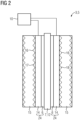
- FIG. 2 shows a simplified cross-sectional view of the fuel cell structure.
- Each of the fuel cells 3 or recombinant fuel cells 5 has a membrane 7 and, on both sides thereof, a catalyst layer 6 and a gas diffusion layer 14.
- the gas diffusion layer 14 and the catalyst layer 6 together form a gas diffusion electrode 24.
- a bipolar plate 15 which establishes the electrical connection to the next fuel cell 3 and in which gas distribution structures 16 are incorporated, through which gas spaces 17 and 18 for the reactants hydrogen and oxygen are formed.
- the electrode 24 adjacent to a gas space 17 for hydrogen is also called the anode
- the operating part 13 of the fuel cell assembly 1 comprises connection technology, sensors, valves, water separators, etc. Therefore, there are connections for the hydrogen supply 19 and discharge 20 and connections for the oxygen supply 21 and discharge 22. Furthermore, at the end of the fuel cell assembly 1 on the operating part side, electrical load connections 23 are led outwards, to which a load (not shown) to be supplied with current from the fuel cell assembly 1 can be connected.
- the recombination fuel cell 5 is arranged directly downstream of the fuel cells 3 in the fuel cell stack 2 in the flow direction 9 of the reactants, so that a compact structure is achieved.
- Figure 3 shows an alternative embodiment of a fuel cell arrangement 1 according to the invention, in which the recombination fuel cell 5 is arranged outside the fuel cell stack 2 downstream of the fuel cells 3 in the flow direction 9 of the reactants.
- a voltage and/or current measuring device 10 is integrated into the recombinant fuel cell 5 (see Figure 2 ).
- the corresponding connections to circuit 8 are located in the area of the other connections.
- Figure 3 Corresponding connections are found on the external recombination fuel cell 5.
- the fuel cell arrangement of the Figure 4 is compared to the embodiment of the Figure 1 by arranging a sheet metal recombination cell 11 between the fuel cells 3 and the recombination fuel cell 5.
- the structure of such a sheet metal recombination cell 11 differs from that of the recombinant fuel cell 5 in that the membrane 7 of the recombinant fuel cell 5 is replaced by a sheet 12, whereby the mechanical stability is increased compared to the recombinant fuel cell 5 and the mechanical or thermal stress due to the reaction of hydrogen with oxygen can already take place in this cell without damaging it, and thus possible damage to the subsequent recombinant fuel cell 5 can be prevented.
Landscapes
- Life Sciences & Earth Sciences (AREA)
- Engineering & Computer Science (AREA)
- Manufacturing & Machinery (AREA)
- Sustainable Development (AREA)
- Sustainable Energy (AREA)
- Chemical & Material Sciences (AREA)
- Chemical Kinetics & Catalysis (AREA)
- Electrochemistry (AREA)
- General Chemical & Material Sciences (AREA)
- Fuel Cell (AREA)
- Separation Using Semi-Permeable Membranes (AREA)
Description
- Die Erfindung betrifft eine Brennstoffzellenanordnung mit Brennstoffzellen und einer Restgasbehandlungsvorrichtung für wasserstoffhaltige und sauerstoffhaltige Restgase der Brennstoffzellen sowie ein Verfahren zur Behandlung wasserstoffhaltiger und sauerstoffhaltiger Restgase von Brennstoffzellen.
- Brennstoffzellen, Brennstoffzellenanordnungen mit einer Mehrzahl von Brennstoffzellen, sowie Verfahren zu deren Betrieb sind im Stand der Technik umfänglich bekannt. Brennstoffzellen sind galvanische Zellen, die bei einer, insbesondere exergonen, chemischen Reaktion von wenigstens zwei Reaktionsgasen freiwerdende Energie zumindest teilweise als elektrische Energie bereitstellen. Brennstoffzellen dienen somit unter anderem der elektrischen, aber unter Umständen auch der thermischen Energieversorgung.
- Brennstoffzellen werden unter anderem bei stationären Anwendungen eingesetzt, um beispielsweise unterbrechungsfreie Energieversorgungen, Inselnetze und/oder dergleichen bereitstellen zu können. Darüber hinaus kann auch Wärmeenergie für Heizungszwecke mit Brennstoffzellen bereitgestellt werden.
- Ferner ist der Einsatz von Brennstoffzellen auch bei Fahrzeugen, beispielsweise Wasserfahrzeugen wie Fähren oder U-Booten, Luftfahrzeugen, aber auch bei Kraftfahrzeugen vorgesehen, insbesondere bei elektrisch antreibbaren Fahrzeugen wie beispielsweise Elektrofahrzeuge, Hybridfahrzeuge oder dergleichen.
- Häufig ist auch vorgesehen, dass die Reichweite von elektrisch antreibbaren Fahrzeugen durch die Nutzung von Brennstoffzellen verbessert werden soll, bei denen neben oder alternativ zum Einsatz von einer jeweiligen Fahrzeugbatterie zur elektrischen Energieversorgung einer elektrischen Antriebseinrichtung des Fahrzeugs auch Brennstoffzellen vorgesehen werden.
- Eine häufig verwendete Art einer Brennstoffzelle ist die Wasserstoff-Sauerstoff-Brennstoffzelle, bei der in einer elektrochemischen Reaktion von Wasserstoff und Sauerstoff in der Regel elektrische Energie und Wärme erzeugt werden. Die Zufuhr von Sauerstoff kann auch durch Luft ersetzt oder ergänzt sein, je nach Konstruktion der Brennstoffzelle. Als Reaktionsprodukt entsteht unter anderem Wasser. Darüber hinaus sind aus der Brennstoffzelle im Bereich der jeweiligen Elektrode entsprechende Restgase abzuführen, so beispielsweise an der als Anode dienenden Elektrode ein wasserstoffhaltiges Restgas und an der als Kathode dienenden Elektrode ein sauerstoffhaltiges Restgas.
- Im bestimmungsgemäßen Betrieb der Wasserstoff-Sauerstoff-Brennstoffzelle wird Wasserstoff der Anode zugeführt, wohingegen Sauerstoff der Kathode zugeführt wird. Die Elektroden stehen über einen Elektrolyten, der beispielsweise durch eine Polymerelektrolytmembran oder dergleichen gebildet sein kann, elektrochemisch miteinander in Wechselwirkung. Das Zuführen des Wasserstoffs kann entweder durch ein reines Wasserstoffgas oder auch durch ein wasserstoffhaltiges Brenngas realisiert sein. Ebenso kann das Zuführen des Sauerstoffs durch reines Sauerstoffgas oder beispielsweise auch in Form von Luft realisiert sein.
- Bei einer derartigen Wasserstoff-Sauerstoff-Brennstoffzelle wird in der Regel eine Gleichspannung zwischen den Elektroden bereitgestellt, die zum Beispiel etwa 1 V oder weniger betragen kann. Daher wird üblicherweise eine Mehrzahl von Brennstoffzellen elektrisch in Reihe geschaltet betrieben und kann zu einem Brennstoffzellenstapel einer Brennstoffzellenanordnung zusammengefasst sein.
- Beim Betrieb von Brennstoffzellen fallen am Austritt nicht umgesetzte Restgase an. Diese werden im Normalfall an die Umgebung abgegeben. Im Falle einer Polymerelektrolyt-Brennstoffzelle sind das zum einen wasserstoffhaltiges Restgas und zum anderen sauerstoffhaltiges Restgas. Ist ein Betrieb der Brennstoffzelle in einem abgeschlossenen System gefordert, müssen die Restgase weggespeichert werden. Um ein sicheres Wegspeichern zu ermöglichen muss der Wasserstoffgehalt in den Restgasen unter die Explosionsgrenze reduziert werden, im besten Fall ganz vermieden werden.
- Nichtbetriebene Module können Wasserstoff auch auf der Sauerstoffseite aufweisen, beispielsweise wenn die Gasräume zur Vermeidung von Korrosion und Oxidierungen mit Wasserstoff beaufschlagt worden sind.
- Vor der Inbetriebnahme der Brennstoffzelle wird zwar erst mit Stickstoff gespült, trotzdem kann auf der Sauerstoffseite "neuer Sauerstoff" auf "alten Wasserstoff" treffen und mit ihm reagieren, wobei thermische Energie in Mengen frei werden kann, welche die Brennstoffzelle(n) beschädigen können.
- Überschüssiger Wasserstoff kann daher oft nachgeschaltet mit sogenannten katalytischen Brennern bzw. Rekombinatoren mit Hilfe von vorhandenem Sauerstoff abreagieren. Diese katalytischen Brenner bzw. Rekombinatoren sind separierte Bauteile.
- Solche Rekombinatoren sind z.B in
US 2008/248369 oderEP 1750321 beschrieben. - Ein Verfahren zur Behandlung wasserstoffhaltiger und sauerstoffhaltiger Restgase von Brennstoffzellen sowie ein Restgasbehandlungssystem offenbart beispielsweise die
WO 2020/038907 A1 . Die Lehre derWO 2020/038907 A1 eignet sich besonders für einen im Wesentlichen geschlossenen Betrieb einer Brennstoffzellenanordnung, bei der die Restgase nicht ohne Weiteres an eine Umgebung, beispielsweise eine Umgebungsatmosphäre oder dergleichen, abgegeben werden sollen. Auch wenn sich diese Lehre bewährt hat, so zeigen sich dennoch Nachteile. Gerade bei Betriebszustandsänderungen der Brennstoffzelle, insbesondere bei einem Einschaltvorgang beziehungsweise bei einem Ausschaltvorgang der Brennstoffzelle, kann im Restgaskreislauf eine unerwünschte Gaszusammensetzung des Restgasgemisches entstehen, die die optimale Nutzung gemäß der Lehre derWO 2020/038907 A1 beeinflussen kann. - Der Erfindung liegt daher die Aufgabe zugrunde, eine Brennstoffzellenanordnung mit Brennstoffzellen und einer Restgasbehandlungsvorrichtung für wasserstoffhaltige und sauerstoffhaltige Restgase der Brennstoffzellen, sowie ein Verfahren zur Behandlung wasserstoffhaltiger und sauerstoffhaltiger Restgase von Brennstoffzellen bereitzustellen, um eine weitgehend optimale Restgasbehandlung realisieren zu können.
- Als Lösung werden mit der Erfindung eine Brennstoffzellenanordnung mit Brennstoffzellen und einer Restgasbehandlungsvorrichtung für wasserstoffhaltige und sauerstoffhaltige Restgase der Brennstoffzellen, sowie ein Verfahren zur Behandlung wasserstoffhaltiger und sauerstoffhaltiger Restgase von Brennstoffzellen gemäß den unabhängigen Ansprüchen vorgeschlagen.
- Vorteilhafte Weiterbildungen ergeben sich durch Merkmale der abhängigen Ansprüche.
- Die Erfindung löst die auf eine Brennstoffzellenanordnung gerichtete Aufgabe, indem sie vorsieht, dass bei einer derartigen Brennstoffzellenanordnung, umfassend mehrere in einem Brennstoffzellenstapel elektrisch und mechanisch zusammengefasste Brennstoffzellen, weiter umfassend eine Restgasbehandlungsvorrichtung für wasserstoffhaltige und sauerstoffhaltige Restgase der Brennstoffzellen, die Restgasbehandlungsvorrichtung eine Rekombinationsbrennstoffzelle mit Katalysator und Membran umfasst, welche über einen von den Brennstoffzellen separierten Stromkreis geleitet ist.
- Der Aufbau der Brennstoffzellenanordnung wird durch eine oder mehrere sogenannte Rekombinationszellen erweitert. Diese Brennstoffzellen sind normale Zellen mit Katalysator und Membran, wie in der Brennstoffzellenanordnung eingesetzt. Die entstehenden Restgase werden in die Rekombinationsbrennstoffzelle geleitet und dort elektrochemisch zu Wasser umgesetzt. Die Rekombinationsbrennstoffzelle wird über einen von den übrigen Brennstoffzelle separierten Stromkreis geleitet.
- In einer vorteilhaften Ausführungsform der Erfindung, ist die Rekombinationsbrennstoffzelle den Brennstoffzellen im Brennstoffzellenstapel direkt nachgeschaltet, was einen kompakten Aufbau ermöglicht.
- In einer alternativen Ausführungsform ist die Rekombinationsbrennstoffzelle außerhalb des Brennstoffzellenstapels angeordnet. Hierbei kann der bisherige Brennstoffzellenstapel unverändert bleiben.
- Gemäss der Erfindung ist vorgesehen dass eine Spannungs- und/oder Strommessvorrichtung in die Rekombinationsbrennstoffzelle integriert oder an die Rekombinationsbrennstoffzelle angeschlossen ist. Damit kann die Umsetzung von Wasserstoff im Restgas gemessen werden und im besten Fall eine Aussage über die Wasserstoffmenge am Ausgang der Rekombinationszelle gegeben werden.
- In einer weiteren vorteilhaften Ausführungsform der Erfindung ist eine Blechrekombinationszelle zwischen den Brennstoffzellen und der Rekombinationsbrennstoffzelle angeordnet, wobei in der Blechrekombinationszelle die Membran der Rekombinationsbrennstoffzelle durch ein Blech ersetzt ist. Durch das Blech in der Zellmitte wird diese Blechrekombinationszelle mechanisch und thermisch stabiler. Infolge der direkten Abreaktion von Reaktantengemischen aus den Brennstoffzellen im Brennstoffzellenstapel in der mechanisch stabileren Blechrekombinationszelle kann eine mögliche Schädigung der nachfolgenden Membran-Rekombinationsbrennstoffzelle verhindert werden.
- Die auf ein Verfahren zur Behandlung wasserstoffhaltiger und sauerstoffhaltiger Restgase von Brennstoffzellen gerichtete Aufgabe wird gelöst durch ein Verfahren, bei dem die Restgase von in einem Brennstoffzellenstapel elektrisch und mechanisch zusammengefassten Brennstoffzellen einer Rekombinationsbrennstoffzelle zugeführt werden, welche über einen von den Brennstoffzellen separierten Stromkreis geleitet ist.
- Vorteilhafter Weise werden die Restgase innerhalb des Brennstoffzellenstapels der Rekombinationsbrennstoffzelle zugeführt.
- Alternativ dazu kann es vorteilhaft sein, wenn die Restgase aus dem Brennstoffzellenstapel herausgeleitet und einer außerhalb des Stapels angeordneten Rekombinationsbrennstoffzelle zugeführt werden.
- Dabei ist es zweckmäßig, wenn Spannung und/oder Stromstärke der Rekombinationsbrennstoffzelle gemessen wird.
- Vorteilhafter Weise strömen Restgase zuerst durch eine Blechrekombinationszelle, in der eine Membran der Rekombinationsbrennstoffzelle durch ein Blech ersetzt ist, bevor sie in die Rekombinationsbrennstoffzelle geleitet werden.
- Mit der Erfindung kann die Rekombination der Restgase direkt im Aufbau des Brennstoffzellenstapels integriert werden. Über die Spannungs- und/oder Strommessung kann die Reaktivität der Rekombinationszelle gemessen werden und es werden keine weiteren Gassensoren benötigt. Es entsteht ein deutlicher geometrischer Vorteil durch die Integration in den Brennstoffzellenstapel. Das Rekombinationssystem kann aufgrund seines Aufbaus optimal gekühlt werden. In bestimmten Fällen wäre auch eine Energierückgewinnung der Reaktanten möglich.
- Die Erfindung wird beispielhaft anhand der Zeichnungen näher erläutert. Es zeigen schematisch und nicht maßstäblich:
- Figur 1
- eine erste Brennstoffzellenanordnung nach der Erfindung,
- Figur 2
- einen prinzipiellen Aufbau einer PEM-Brennstoffzelle,
- Figur 3
- eine zweite Brennstoffzellenanordnung nach der Erfindung und
- Figur 4
- eine dritte Brennstoffzellenanordnung nach der Erfindung.
-
FIG 1 zeigt in vereinfachter Darstellung eine Brennstoffzellenanordnung 1, die einen Brennstoffzellenstapel 2 und einen Betriebsteil 13 umfasst. Der Brennstoffzellenstapel 2 besteht aus mehreren aufeinander gestapelten und hierdurch elektrisch in Reihe geschalteten einzelnen Brennstoffzellen 3, hier PEM-Brennstoffzellen. - Weiter zeigt die
Figur 1 eine erfindungsgemäße Restgasbehandlungsvorrichtung 4 für wasserstoffhaltige und sauerstoffhaltige Restgase der Brennstoffzellen 3 des Brennstoffzellenstapels 2. Diese Restgasbehandlungsvorrichtung 4 umfasst eine Rekombinationsbrennstoffzelle 5, deren prinzipieller Aufbau sich nicht von dem einer Brennstoffzelle 3 des Brennstoffzellenstapels 2 unterscheidet. Die Rekombinationsbrennstoffzelle 5 ist bzgl. einer Strömungsrichtung 9 der Reaktanden den Brennstoffzellen 3 nachgeschaltet, aber nicht mit diesen elektrisch in Reihe geschaltet, sondern wird über einen von den Brennstoffzellen 3 separierten Stromkreis 8 geführt. -
Figur 2 zeigt in vereinfachter Form im Schnitt den Brennstoffzellenaufbau. Jede der Brennstoffzellen 3 bzw. Rekombinationsbrennstoffzellen 5 weist eine Membran 7 und beidseitig davon jeweils eine Katalysatorschicht 6 und eine Gasdiffusionsschicht 14 auf. Gasdiffusionsschicht 14 und Katalysatorschicht 6 bilden zusammen eine Gasdiffusionselektrode 24. Daran schließt sich eine Bipolarplatte 15 an, die die elektrische Verbindung zur nächsten Brennstoffzelle 3 herstellt und in der Gasverteilerstrukturen 16 eingebracht sind, durch die Gasräume 17 und 18 für die Reaktanden Wasserstoff und Sauerstoff ausgebildet sind. Die an einem Gasraum 17 für Wasserstoff anliegende Elektrode 24 wird auch Anode und die an einem Gasraum 18 für Sauerstoff anliegende Elektrode 24 wird auch Kathode genannt. Kanäle zur Zu- und Abfuhr der Reaktanden zu bzw. von den Brennstoffzellen, Dichtungen etc. sind zur Vereinfachung der Darstellung nicht gezeigt. - Das Betriebsteil 13 der Brennstoffzellenanordnung 1 umfasst Anschlusstechnik, Sensoren, Ventile, Wasserabscheider, etc. Es finden sich daher Anschlüsse für die Wasserstoffzufuhr 19 bzw. -abfuhr 20 und Anschlüsse für die Sauerstoffzufuhr 21 bzw. -abfuhr 22. Weiterhin sind am betriebsteilseitigen Ende der Brennstoffzellenanordnung 1 elektrische Lastanschlüsse 23 nach außen geführt, an die eine mit Strom der Brennstoffzellenanordnung 1 zu speisende Last (nicht dargestellt) anschließbar ist. Im Ausführungsbeispiel der
Figur 1 ist die Rekombinationsbrennstoffzelle 5 den Brennstoffzellen 3 im Brennstoffzellenstapel 2 in Strömungsrichtung 9 der Reaktanden direkt nachgeschaltet, sodass ein kompakter Aufbau erreicht wird. -
Figur 3 zeigt eine alternative Ausführungsform einer Brennstoffzellenanordnung 1 nach der Erfindung, bei der die Rekombinationsbrennstoffzelle 5 außerhalb des Brennstoffzellenstapels 2 in Strömungsrichtung 9 der Reaktanden den Brennstoffzellen 3 nachgeschaltet ist. - Gemäß der Erfindung ist eine Spannungs- und/oder Strommessvorrichtung 10 in die Rekombinationsbrennstoffzelle 5 integriert (s.
Figur 2 ). In den Ausführungsbeispielen derFiguren 1 und4 sind entsprechende Anschlüsse zum Stromkreis 8 im Bereich der übrigen Anschlüsse angeordnet. InFigur 3 finden sich entsprechende Anschlüsse an der externen Rekombinationsbrennstoffzelle 5. - Die Brennstoffzellenanordnung der
Figur 4 ist gegenüber dem Ausführungsbeispiel derFigur 1 dadurch verändert, dass eine Blechrekombinationszelle 11 zwischen den Brennstoffzellen 3 und der Rekombinationsbrennstoffzelle 5 angeordnet ist. Der Aufbau einer solchen Blechrekombinationszelle 11 unterscheidet sich von dem der Rekombinationsbrennstoffzelle 5 dadurch, dass die Membran 7 der Rekombinationsbrennstoffzelle 5 durch ein Blech 12 ersetzt ist, wodurch die mechanische Stabilität gegenüber der Rekombinationsbrennstoffzelle 5 erhöht ist und die mechanische bzw. thermische Belastung infolge der Abreaktion von Wasserstoff mit Sauerstoff bereits in dieser Zelle erfolgen kann, ohne diese zu beschädigen, und somit eine mögliche Schädigung der nachfolgenden Rekombinationsbrennstoffzelle 5 verhindert werden kann.
Claims (8)
- Brennstoffzellenanordnung (1) umfassend mehrere in einem Brennstoffzellenstapel (2) elektrisch und mechanisch zusammengefasste Brennstoffzellen (3), weiter umfassend eine Restgasbehandlungsvorrichtung (4) für wasserstoffhaltige und sauerstoffhaltige Restgase der Brennstoffzellen (3), wobei die Restgasbehandlungsvorrichtung (4) eine Rekombinationsbrennstoffzelle (5) mit Katalysator (6) und Membran (7) umfasst, welche über einen von den Brennstoffzellen (3) separierten Stromkreis (8) geleitet ist, dadurch gekennzeichnet, dass eine Spannungs- und/oder Strommessvorrichtung (10) in die Rekombinationsbrennstoffzelle (5) integriert oder an die Rekombinationsbrennstoffzelle (5) angeschlossen ist.
- Brennstoffzellenanordnung (1) nach Anspruch 1, wobei die Rekombinationsbrennstoffzelle (5) den Brennstoffzellen (3) im Brennstoffzellenstapel (2) in Strömungsrichtung (9) der Reaktanden direkt nachgeschaltet ist.
- Brennstoffzellenanordnung (1) nach Anspruch 1, wobei die Rekombinationsbrennstoffzelle (5) außerhalb des Brennstoffzellenstapels (2) in Strömungsrichtung (9) der Reaktanden den Brennstoffzellen (3) nachgeschaltet ist.
- Brennstoffzellenanordnung (1) nach einem der vorhergehenden Ansprüche, wobei eine Blechrekombinationszelle (11) zwischen den Brennstoffzellen (3) und der Rekombinationsbrennstoffzelle (5) angeordnet ist, wobei in der Blechrekombinationszelle (11) die Membran (7) der Rekombinationsbrennstoffzelle (5) durch ein Blech (12) ersetzt ist.
- Verfahren zur Behandlung wasserstoffhaltiger und sauerstoffhaltiger Restgase von Brennstoffzellen (3), bei dem die Restgase von in einem Brennstoffzellenstapel (2) elektrisch und mechanisch zusammengefassten Brennstoffzellen (3) einer Rekombinationsbrennstoffzelle (5) zugeführt werden, welche über einen von den Brennstoffzellen (3) separierten Stromkreis (8) geleitet ist, dadurch gekennzeichnet, dass Spannung und/oder Stromstärke der Rekombinationsbrennstoffzelle (5) gemessen wird.
- Verfahren nach Anspruch 5, wobei die Restgase innerhalb des Brennstoffzellenstapels (2) der Rekombinationsbrennstoffzelle (5) zugeführt werden.
- Verfahren nach Anspruch 5, wobei die Restgase aus dem Brennstoffzellenstapel (2) herausgeleitet und der Rekombinationsbrennstoffzelle (5) zugeführt werden.
- Verfahren nach einem der Ansprüche 5 bis 7, wobei Restgase zuerst durch eine Blechrekombinationszelle (11) strömen, in der an der Stelle einer Membran (7), wie in der Rekombinationsbrennstoffzelle (5), ein Blech (12) angeordnet ist, bevor sie in die Rekombinationsbrennstoffzelle (5) geleitet werden.
Applications Claiming Priority (2)
| Application Number | Priority Date | Filing Date | Title |
|---|---|---|---|
| DE102021208146.0A DE102021208146A1 (de) | 2021-07-28 | 2021-07-28 | Behandlung wasserstoffhaltiger und sauerstoffhaltiger Restgase von Brennstoffzellen |
| PCT/EP2022/069251 WO2023006396A1 (de) | 2021-07-28 | 2022-07-11 | Behandlung wasserstoffhaltiger und sauerstoffhaltiger restgase von brennstoffzellen |
Publications (2)
| Publication Number | Publication Date |
|---|---|
| EP4342013A1 EP4342013A1 (de) | 2024-03-27 |
| EP4342013B1 true EP4342013B1 (de) | 2025-06-04 |
Family
ID=82786806
Family Applications (1)
| Application Number | Title | Priority Date | Filing Date |
|---|---|---|---|
| EP22750781.1A Active EP4342013B1 (de) | 2021-07-28 | 2022-07-11 | Behandlung wasserstoffhaltiger und sauerstoffhaltiger restgase von brennstoffzellen |
Country Status (8)
| Country | Link |
|---|---|
| US (1) | US20240258545A1 (de) |
| EP (1) | EP4342013B1 (de) |
| KR (1) | KR20240036092A (de) |
| CA (1) | CA3227578A1 (de) |
| DE (1) | DE102021208146A1 (de) |
| ES (1) | ES3040367T3 (de) |
| PT (1) | PT4342013T (de) |
| WO (1) | WO2023006396A1 (de) |
Citations (1)
| Publication number | Priority date | Publication date | Assignee | Title |
|---|---|---|---|---|
| EP1750321B1 (de) * | 2005-07-29 | 2015-12-02 | Siemens Aktiengesellschaft | Verfahren zum Betrieb einer Brennstoffzellenanordnung mit einem Gasgemisch mit einem Reaktionsgasanteil und einem Inertgasanteil sowie dafür geeignete Brennstoffzellenanordnung |
Family Cites Families (3)
| Publication number | Priority date | Publication date | Assignee | Title |
|---|---|---|---|---|
| US20050014037A1 (en) * | 2002-12-04 | 2005-01-20 | Chris Boyer | Fuel cell with recombination catalyst |
| US20080248369A1 (en) * | 2007-04-04 | 2008-10-09 | De Vaal Jacob W | Fuel cell system with flame arresting recombiner |
| EP3614475A1 (de) * | 2018-08-20 | 2020-02-26 | Siemens Aktiengesellschaft | Verfahren zur behandlung wasserstoffhaltiger und sauerstoffhaltiger restgase von brennstoffzellen sowie restgasbehandlungssystem |
-
2021
- 2021-07-28 DE DE102021208146.0A patent/DE102021208146A1/de not_active Withdrawn
-
2022
- 2022-07-11 WO PCT/EP2022/069251 patent/WO2023006396A1/de not_active Ceased
- 2022-07-11 KR KR1020247006287A patent/KR20240036092A/ko active Pending
- 2022-07-11 EP EP22750781.1A patent/EP4342013B1/de active Active
- 2022-07-11 CA CA3227578A patent/CA3227578A1/en active Pending
- 2022-07-11 US US18/292,363 patent/US20240258545A1/en active Pending
- 2022-07-11 ES ES22750781T patent/ES3040367T3/es active Active
- 2022-07-11 PT PT227507811T patent/PT4342013T/pt unknown
Patent Citations (1)
| Publication number | Priority date | Publication date | Assignee | Title |
|---|---|---|---|---|
| EP1750321B1 (de) * | 2005-07-29 | 2015-12-02 | Siemens Aktiengesellschaft | Verfahren zum Betrieb einer Brennstoffzellenanordnung mit einem Gasgemisch mit einem Reaktionsgasanteil und einem Inertgasanteil sowie dafür geeignete Brennstoffzellenanordnung |
Also Published As
| Publication number | Publication date |
|---|---|
| WO2023006396A1 (de) | 2023-02-02 |
| CA3227578A1 (en) | 2023-02-02 |
| DE102021208146A1 (de) | 2023-02-02 |
| PT4342013T (pt) | 2025-07-30 |
| US20240258545A1 (en) | 2024-08-01 |
| ES3040367T3 (en) | 2025-10-30 |
| KR20240036092A (ko) | 2024-03-19 |
| EP4342013A1 (de) | 2024-03-27 |
Similar Documents
| Publication | Publication Date | Title |
|---|---|---|
| EP0596366B1 (de) | Verfahren und Einrichtung zur Wasser- und/oder Inertgasentsorgung eines Brennstoffzellenblocks | |
| DE19857398B4 (de) | Brennstoffzellensystem, insbesondere für elektromotorisch angetriebene Fahrzeuge | |
| DE102014210511B4 (de) | Brennstoffzellenverwaltungsverfahren | |
| EP1333517A2 (de) | Brennstoffzellenvorrichtung und System mir derartiger Brennstoffzellenvorrichtung | |
| EP4182986B1 (de) | Brennstoffzellenstapel, brennstoffzellenvorrichtung sowie brennstoffzellen-fahrzeug | |
| EP1256142B1 (de) | Alkalische direkt-methanol brennstoffzelle | |
| EP4342013B1 (de) | Behandlung wasserstoffhaltiger und sauerstoffhaltiger restgase von brennstoffzellen | |
| EP3676898B1 (de) | Verfahren zum schutz von einzelzellen, brennstoffzellensystem und kraftfahrzeug | |
| DE102010054305A1 (de) | Brennstoffzellenstapel mit mehreren Brennstoffzellen | |
| DE102008041225A1 (de) | Brennstoffzelle sowie Verfahren zum Betreiben derselben | |
| DE102017101515A1 (de) | Brennstoffzellenstapel und Brennstoffzellensystem mit einem solchen | |
| WO2006056319A1 (de) | Verfahren zum betreiben eines brennstoffzellenstapels | |
| EP1665443B1 (de) | Brennstoffzelle und zugehöriges brennstoffzellenmodul | |
| EP2850687B1 (de) | Elektrischer energiespeicher | |
| DE102015215497B4 (de) | Brennstoffzellenstapel mit variabler Segmentierung sowie Brennstoffzellensystem und Fahrzeug mit einem solchen | |
| DE102011009958B4 (de) | Brennstoffzellensystem mit reduzierter Kohlenstoffkorrosion sowie Verfahren zum Betreiben eines Brennstoffzellensystems | |
| DE102012213037A1 (de) | Speichereinrichtung für elektrische Energie, insbesondere Batterie oder Batteriezelle | |
| DE102018210165A1 (de) | Spannsystem für Brennstoffzellenstapel und Brennstoffzellenstapel mit einem solchen | |
| DE112006002510T5 (de) | Brennstoffzelle | |
| WO2002027834A2 (de) | Brennstoffzellenmodul | |
| WO2004006370A2 (de) | Niedertemperatur-brennstoffzellenstapel | |
| DE102016116117A1 (de) | Vorrichtung zur Kompression einer Brennstoffzellenanordnung, Brennstoffzellenanordnung und Kraftfahrzeug | |
| DE102022203070A1 (de) | Brennstoffzelle mit reduzierendem Strömungsquerschnitt | |
| DE102019208311A1 (de) | Segmentierte Einlageplatte für einen Brennstoffzellenstapel | |
| DE102017100738A1 (de) | Brennstoffzellenstapel mit erhöhter Beständigkeit gegenüber Spannungsumkehr sowie Brennstoffzellensystem und Fahrzeug mit einem solchen |
Legal Events
| Date | Code | Title | Description |
|---|---|---|---|
| STAA | Information on the status of an ep patent application or granted ep patent |
Free format text: STATUS: UNKNOWN |
|
| STAA | Information on the status of an ep patent application or granted ep patent |
Free format text: STATUS: THE INTERNATIONAL PUBLICATION HAS BEEN MADE |
|
| PUAI | Public reference made under article 153(3) epc to a published international application that has entered the european phase |
Free format text: ORIGINAL CODE: 0009012 |
|
| STAA | Information on the status of an ep patent application or granted ep patent |
Free format text: STATUS: REQUEST FOR EXAMINATION WAS MADE |
|
| 17P | Request for examination filed |
Effective date: 20231222 |
|
| AK | Designated contracting states |
Kind code of ref document: A1 Designated state(s): AL AT BE BG CH CY CZ DE DK EE ES FI FR GB GR HR HU IE IS IT LI LT LU LV MC MK MT NL NO PL PT RO RS SE SI SK SM TR |
|
| DAV | Request for validation of the european patent (deleted) | ||
| DAX | Request for extension of the european patent (deleted) | ||
| GRAP | Despatch of communication of intention to grant a patent |
Free format text: ORIGINAL CODE: EPIDOSNIGR1 |
|
| STAA | Information on the status of an ep patent application or granted ep patent |
Free format text: STATUS: GRANT OF PATENT IS INTENDED |
|
| INTG | Intention to grant announced |
Effective date: 20250124 |
|
| GRAS | Grant fee paid |
Free format text: ORIGINAL CODE: EPIDOSNIGR3 |
|
| GRAA | (expected) grant |
Free format text: ORIGINAL CODE: 0009210 |
|
| STAA | Information on the status of an ep patent application or granted ep patent |
Free format text: STATUS: THE PATENT HAS BEEN GRANTED |
|
| AK | Designated contracting states |
Kind code of ref document: B1 Designated state(s): AL AT BE BG CH CY CZ DE DK EE ES FI FR GB GR HR HU IE IS IT LI LT LU LV MC MK MT NL NO PL PT RO RS SE SI SK SM TR |
|
| REG | Reference to a national code |
Ref country code: GB Ref legal event code: FG4D Free format text: NOT ENGLISH |
|
| REG | Reference to a national code |
Ref country code: CH Ref legal event code: EP |
|
| REG | Reference to a national code |
Ref country code: DE Ref legal event code: R096 Ref document number: 502022004183 Country of ref document: DE |
|
| REG | Reference to a national code |
Ref country code: IE Ref legal event code: FG4D Free format text: LANGUAGE OF EP DOCUMENT: GERMAN |
|
| REG | Reference to a national code |
Ref country code: PT Ref legal event code: SC4A Ref document number: 4342013 Country of ref document: PT Date of ref document: 20250730 Kind code of ref document: T Free format text: AVAILABILITY OF NATIONAL TRANSLATION Effective date: 20250724 |
|
| REG | Reference to a national code |
Ref country code: SE Ref legal event code: TRGR |
|
| REG | Reference to a national code |
Ref country code: NL Ref legal event code: MP Effective date: 20250604 |
|
| PG25 | Lapsed in a contracting state [announced via postgrant information from national office to epo] |
Ref country code: FI Free format text: LAPSE BECAUSE OF FAILURE TO SUBMIT A TRANSLATION OF THE DESCRIPTION OR TO PAY THE FEE WITHIN THE PRESCRIBED TIME-LIMIT Effective date: 20250604 |
|
| PGFP | Annual fee paid to national office [announced via postgrant information from national office to epo] |
Ref country code: ES Payment date: 20250812 Year of fee payment: 4 Ref country code: PT Payment date: 20250725 Year of fee payment: 4 |
|
| PGFP | Annual fee paid to national office [announced via postgrant information from national office to epo] |
Ref country code: DE Payment date: 20250728 Year of fee payment: 4 |
|
| REG | Reference to a national code |
Ref country code: LT Ref legal event code: MG9D |
|
| PG25 | Lapsed in a contracting state [announced via postgrant information from national office to epo] |
Ref country code: GR Free format text: LAPSE BECAUSE OF FAILURE TO SUBMIT A TRANSLATION OF THE DESCRIPTION OR TO PAY THE FEE WITHIN THE PRESCRIBED TIME-LIMIT Effective date: 20250905 |
|
| PGFP | Annual fee paid to national office [announced via postgrant information from national office to epo] |
Ref country code: NO Payment date: 20250718 Year of fee payment: 4 |
|
| PG25 | Lapsed in a contracting state [announced via postgrant information from national office to epo] |
Ref country code: PL Free format text: LAPSE BECAUSE OF FAILURE TO SUBMIT A TRANSLATION OF THE DESCRIPTION OR TO PAY THE FEE WITHIN THE PRESCRIBED TIME-LIMIT Effective date: 20250604 |
|
| PGFP | Annual fee paid to national office [announced via postgrant information from national office to epo] |
Ref country code: IT Payment date: 20250731 Year of fee payment: 4 |
|
| PG25 | Lapsed in a contracting state [announced via postgrant information from national office to epo] |
Ref country code: BG Free format text: LAPSE BECAUSE OF FAILURE TO SUBMIT A TRANSLATION OF THE DESCRIPTION OR TO PAY THE FEE WITHIN THE PRESCRIBED TIME-LIMIT Effective date: 20250604 |
|
| PG25 | Lapsed in a contracting state [announced via postgrant information from national office to epo] |
Ref country code: HR Free format text: LAPSE BECAUSE OF FAILURE TO SUBMIT A TRANSLATION OF THE DESCRIPTION OR TO PAY THE FEE WITHIN THE PRESCRIBED TIME-LIMIT Effective date: 20250604 |
|
| PGFP | Annual fee paid to national office [announced via postgrant information from national office to epo] |
Ref country code: AT Payment date: 20251020 Year of fee payment: 4 Ref country code: FR Payment date: 20250725 Year of fee payment: 4 |
|
| PGFP | Annual fee paid to national office [announced via postgrant information from national office to epo] |
Ref country code: SE Payment date: 20250725 Year of fee payment: 4 |
|
| PG25 | Lapsed in a contracting state [announced via postgrant information from national office to epo] |
Ref country code: RS Free format text: LAPSE BECAUSE OF FAILURE TO SUBMIT A TRANSLATION OF THE DESCRIPTION OR TO PAY THE FEE WITHIN THE PRESCRIBED TIME-LIMIT Effective date: 20250904 |
|
| PG25 | Lapsed in a contracting state [announced via postgrant information from national office to epo] |
Ref country code: LV Free format text: LAPSE BECAUSE OF FAILURE TO SUBMIT A TRANSLATION OF THE DESCRIPTION OR TO PAY THE FEE WITHIN THE PRESCRIBED TIME-LIMIT Effective date: 20250604 |
|
| REG | Reference to a national code |
Ref country code: ES Ref legal event code: FG2A Ref document number: 3040367 Country of ref document: ES Kind code of ref document: T3 Effective date: 20251030 |
|
| PG25 | Lapsed in a contracting state [announced via postgrant information from national office to epo] |
Ref country code: NL Free format text: LAPSE BECAUSE OF FAILURE TO SUBMIT A TRANSLATION OF THE DESCRIPTION OR TO PAY THE FEE WITHIN THE PRESCRIBED TIME-LIMIT Effective date: 20250604 |
|
| PG25 | Lapsed in a contracting state [announced via postgrant information from national office to epo] |
Ref country code: IS Free format text: LAPSE BECAUSE OF FAILURE TO SUBMIT A TRANSLATION OF THE DESCRIPTION OR TO PAY THE FEE WITHIN THE PRESCRIBED TIME-LIMIT Effective date: 20251004 |
|
| PG25 | Lapsed in a contracting state [announced via postgrant information from national office to epo] |
Ref country code: SM Free format text: LAPSE BECAUSE OF FAILURE TO SUBMIT A TRANSLATION OF THE DESCRIPTION OR TO PAY THE FEE WITHIN THE PRESCRIBED TIME-LIMIT Effective date: 20250604 |
|
| PG25 | Lapsed in a contracting state [announced via postgrant information from national office to epo] |
Ref country code: CZ Free format text: LAPSE BECAUSE OF FAILURE TO SUBMIT A TRANSLATION OF THE DESCRIPTION OR TO PAY THE FEE WITHIN THE PRESCRIBED TIME-LIMIT Effective date: 20250604 |
|
| PG25 | Lapsed in a contracting state [announced via postgrant information from national office to epo] |
Ref country code: EE Free format text: LAPSE BECAUSE OF FAILURE TO SUBMIT A TRANSLATION OF THE DESCRIPTION OR TO PAY THE FEE WITHIN THE PRESCRIBED TIME-LIMIT Effective date: 20250604 |
|
| PG25 | Lapsed in a contracting state [announced via postgrant information from national office to epo] |
Ref country code: SK Free format text: LAPSE BECAUSE OF FAILURE TO SUBMIT A TRANSLATION OF THE DESCRIPTION OR TO PAY THE FEE WITHIN THE PRESCRIBED TIME-LIMIT Effective date: 20250604 |
|
| REG | Reference to a national code |
Ref country code: CH Ref legal event code: H13 Free format text: ST27 STATUS EVENT CODE: U-0-0-H10-H13 (AS PROVIDED BY THE NATIONAL OFFICE) Effective date: 20260224 |
|
| REG | Reference to a national code |
Ref country code: DE Ref legal event code: R097 Ref document number: 502022004183 Country of ref document: DE |
|
| PG25 | Lapsed in a contracting state [announced via postgrant information from national office to epo] |
Ref country code: RO Free format text: LAPSE BECAUSE OF FAILURE TO SUBMIT A TRANSLATION OF THE DESCRIPTION OR TO PAY THE FEE WITHIN THE PRESCRIBED TIME-LIMIT Effective date: 20250604 |
|
| PG25 | Lapsed in a contracting state [announced via postgrant information from national office to epo] |
Ref country code: LU Free format text: LAPSE BECAUSE OF NON-PAYMENT OF DUE FEES Effective date: 20250711 |
|
| REG | Reference to a national code |
Ref country code: BE Ref legal event code: MM Effective date: 20250731 |
|
| PG25 | Lapsed in a contracting state [announced via postgrant information from national office to epo] |
Ref country code: MC Free format text: LAPSE BECAUSE OF FAILURE TO SUBMIT A TRANSLATION OF THE DESCRIPTION OR TO PAY THE FEE WITHIN THE PRESCRIBED TIME-LIMIT Effective date: 20250604 |
|
| PLBE | No opposition filed within time limit |
Free format text: ORIGINAL CODE: 0009261 |
|
| STAA | Information on the status of an ep patent application or granted ep patent |
Free format text: STATUS: NO OPPOSITION FILED WITHIN TIME LIMIT |
|
| PG25 | Lapsed in a contracting state [announced via postgrant information from national office to epo] |
Ref country code: DK Free format text: LAPSE BECAUSE OF FAILURE TO SUBMIT A TRANSLATION OF THE DESCRIPTION OR TO PAY THE FEE WITHIN THE PRESCRIBED TIME-LIMIT Effective date: 20250604 |
|
| PG25 | Lapsed in a contracting state [announced via postgrant information from national office to epo] |
Ref country code: BE Free format text: LAPSE BECAUSE OF NON-PAYMENT OF DUE FEES Effective date: 20250731 |
|
| REG | Reference to a national code |
Ref country code: CH Ref legal event code: L10 Free format text: ST27 STATUS EVENT CODE: U-0-0-L10-L00 (AS PROVIDED BY THE NATIONAL OFFICE) Effective date: 20260416 |
|
| PG25 | Lapsed in a contracting state [announced via postgrant information from national office to epo] |
Ref country code: CH Free format text: LAPSE BECAUSE OF NON-PAYMENT OF DUE FEES Effective date: 20250731 |