EP4342440A2 - Dispositif de stimulation du clitoris avec un champ de pression variable et procédé de production d'un champ de pression variable - Google Patents
Dispositif de stimulation du clitoris avec un champ de pression variable et procédé de production d'un champ de pression variable Download PDFInfo
- Publication number
- EP4342440A2 EP4342440A2 EP24156254.5A EP24156254A EP4342440A2 EP 4342440 A2 EP4342440 A2 EP 4342440A2 EP 24156254 A EP24156254 A EP 24156254A EP 4342440 A2 EP4342440 A2 EP 4342440A2
- Authority
- EP
- European Patent Office
- Prior art keywords
- displaceable
- chamber wall
- chamber
- wall section
- section
- Prior art date
- Legal status (The legal status is an assumption and is not a legal conclusion. Google has not performed a legal analysis and makes no representation as to the accuracy of the status listed.)
- Granted
Links
Images






Classifications
-
- A—HUMAN NECESSITIES
- A61—MEDICAL OR VETERINARY SCIENCE; HYGIENE
- A61H—PHYSICAL THERAPY APPARATUS, e.g. DEVICES FOR LOCATING OR STIMULATING REFLEX POINTS IN THE BODY; ARTIFICIAL RESPIRATION; MASSAGE; BATHING DEVICES FOR SPECIAL THERAPEUTIC OR HYGIENIC PURPOSES OR SPECIFIC PARTS OF THE BODY
- A61H19/00—Massage for the genitals; Devices for improving sexual intercourse
- A61H19/30—Devices for external stimulation of the genitals
- A61H19/34—For clitoral stimulation
-
- A—HUMAN NECESSITIES
- A61—MEDICAL OR VETERINARY SCIENCE; HYGIENE
- A61H—PHYSICAL THERAPY APPARATUS, e.g. DEVICES FOR LOCATING OR STIMULATING REFLEX POINTS IN THE BODY; ARTIFICIAL RESPIRATION; MASSAGE; BATHING DEVICES FOR SPECIAL THERAPEUTIC OR HYGIENIC PURPOSES OR SPECIFIC PARTS OF THE BODY
- A61H9/00—Pneumatic or hydraulic massage
- A61H9/0007—Pulsating
-
- A—HUMAN NECESSITIES
- A61—MEDICAL OR VETERINARY SCIENCE; HYGIENE
- A61H—PHYSICAL THERAPY APPARATUS, e.g. DEVICES FOR LOCATING OR STIMULATING REFLEX POINTS IN THE BODY; ARTIFICIAL RESPIRATION; MASSAGE; BATHING DEVICES FOR SPECIAL THERAPEUTIC OR HYGIENIC PURPOSES OR SPECIFIC PARTS OF THE BODY
- A61H19/00—Massage for the genitals; Devices for improving sexual intercourse
- A61H19/30—Devices for external stimulation of the genitals
-
- A—HUMAN NECESSITIES
- A61—MEDICAL OR VETERINARY SCIENCE; HYGIENE
- A61H—PHYSICAL THERAPY APPARATUS, e.g. DEVICES FOR LOCATING OR STIMULATING REFLEX POINTS IN THE BODY; ARTIFICIAL RESPIRATION; MASSAGE; BATHING DEVICES FOR SPECIAL THERAPEUTIC OR HYGIENIC PURPOSES OR SPECIFIC PARTS OF THE BODY
- A61H9/00—Pneumatic or hydraulic massage
- A61H9/005—Pneumatic massage
-
- A—HUMAN NECESSITIES
- A61—MEDICAL OR VETERINARY SCIENCE; HYGIENE
- A61H—PHYSICAL THERAPY APPARATUS, e.g. DEVICES FOR LOCATING OR STIMULATING REFLEX POINTS IN THE BODY; ARTIFICIAL RESPIRATION; MASSAGE; BATHING DEVICES FOR SPECIAL THERAPEUTIC OR HYGIENIC PURPOSES OR SPECIFIC PARTS OF THE BODY
- A61H9/00—Pneumatic or hydraulic massage
- A61H9/005—Pneumatic massage
- A61H9/0057—Suction
-
- A—HUMAN NECESSITIES
- A61—MEDICAL OR VETERINARY SCIENCE; HYGIENE
- A61H—PHYSICAL THERAPY APPARATUS, e.g. DEVICES FOR LOCATING OR STIMULATING REFLEX POINTS IN THE BODY; ARTIFICIAL RESPIRATION; MASSAGE; BATHING DEVICES FOR SPECIAL THERAPEUTIC OR HYGIENIC PURPOSES OR SPECIFIC PARTS OF THE BODY
- A61H2201/00—Characteristics of apparatus not provided for in the preceding codes
- A61H2201/01—Constructive details
- A61H2201/0119—Support for the device
- A61H2201/0153—Support for the device hand-held
-
- A—HUMAN NECESSITIES
- A61—MEDICAL OR VETERINARY SCIENCE; HYGIENE
- A61H—PHYSICAL THERAPY APPARATUS, e.g. DEVICES FOR LOCATING OR STIMULATING REFLEX POINTS IN THE BODY; ARTIFICIAL RESPIRATION; MASSAGE; BATHING DEVICES FOR SPECIAL THERAPEUTIC OR HYGIENIC PURPOSES OR SPECIFIC PARTS OF THE BODY
- A61H2201/00—Characteristics of apparatus not provided for in the preceding codes
- A61H2201/01—Constructive details
- A61H2201/0157—Constructive details portable
-
- A—HUMAN NECESSITIES
- A61—MEDICAL OR VETERINARY SCIENCE; HYGIENE
- A61H—PHYSICAL THERAPY APPARATUS, e.g. DEVICES FOR LOCATING OR STIMULATING REFLEX POINTS IN THE BODY; ARTIFICIAL RESPIRATION; MASSAGE; BATHING DEVICES FOR SPECIAL THERAPEUTIC OR HYGIENIC PURPOSES OR SPECIFIC PARTS OF THE BODY
- A61H2201/00—Characteristics of apparatus not provided for in the preceding codes
- A61H2201/12—Driving means
- A61H2201/1207—Driving means with electric or magnetic drive
- A61H2201/123—Linear drive
-
- A—HUMAN NECESSITIES
- A61—MEDICAL OR VETERINARY SCIENCE; HYGIENE
- A61H—PHYSICAL THERAPY APPARATUS, e.g. DEVICES FOR LOCATING OR STIMULATING REFLEX POINTS IN THE BODY; ARTIFICIAL RESPIRATION; MASSAGE; BATHING DEVICES FOR SPECIAL THERAPEUTIC OR HYGIENIC PURPOSES OR SPECIFIC PARTS OF THE BODY
- A61H2201/00—Characteristics of apparatus not provided for in the preceding codes
- A61H2201/50—Control means thereof
- A61H2201/5005—Control means thereof for controlling frequency distribution, modulation or interference of a driving signal
Definitions
- the invention relates to a device for stimulating the clitoris with a variable pressure field and a method for generating a variable pressure field.
- a stimulation device with a drive train an electrochemical energy storage in the form of an accumulator or a battery unit and a control unit is described, the drive train of which consists of a rotating electric motor with an eccentric shaft, a connecting rod and a piston in at least one chamber of the stimulation device.
- the control current in the form of direct current supplied to the rotating electric motor varies or controls the speed of the electric motor and thus ultimately the frequency of the piston movement.
- the stroke of the piston is determined by the defined eccentric travel and therefore cannot be changed during operation.
- the drive unit of which is that from the document DE 10 2013 110 501 A1 “Simplified in structure” and intended to produce a “greater variety of different vibrations”.
- the drive train there is no rotating electric motor here, but rather an electric linear motor with coil elements in the primary part and at least one axially displaceably guided magnetic core arranged parallel to the coil element and made up of at least two permanent magnets arranged in opposite poles as a secondary part.
- the magnetic core is mechanically connected to at least one actuation section of the first chamber wall of the stimulation device.
- the rotor-side magnetic core is moved axially back and forth.
- the maximum axial displacement path of the magnetic core is determined by the number, structure, arrangement and circuit of the coils.
- the object of the invention is to provide a device for stimulating the clitoris with a variable pressure field and a method for generating a variable pressure field, which enable a device with improved operating properties.
- a device for stimulating the clitoris with a variable pressure field comprises: a housing on which a handle portion and a stimulation portion are formed, a drive device arranged in the housing and configured to repeatedly provide a drive movement, a pressure chamber arranged in the housing to provide a variable pressure field and is surrounded at least in sections by a chamber wall, a displaceable chamber wall section, which forms a section of the chamber wall and couples to the drive device, such that the displaceable chamber wall section can be repeatedly displaced between different wall positions in response to the drive movement coupled thereto, whereby a chamber volume of the pressure chamber Generating the variable pressure field is repeatedly enlarged and reduced, a housing opening which is arranged in the stimulation section and is in fluid communication with the pressure chamber, such that the variable pressure field generated by the pressure chamber can be delivered via the housing opening in the form of positive and negative pressures, in particular for acting on the clitoris, and a battery device which is set up to provide drive energy for the drive device, wherein in the drive device
- a method for generating a variable pressure field comprises the following steps: providing a stimulation device with a housing on which a handle section and a stimulation section are formed, repeatedly providing a drive movement by means of a drive device arranged in the housing is, providing a variable pressure field in a pressure chamber which is arranged in the housing and is at least partially surrounded by a chamber wall, displacing a displaceable chamber wall section, which forms a section of the chamber wall and couples to the drive device, such that the displaceable chamber wall section reacts to the coupled drive movement is repeatedly shifted between different wall positions, whereby a chamber volume of the pressure chamber is repeatedly increased and decreased for generating the variable pressure field, acting the variable pressure field in the form of negative and positive pressures on the clitoris through a housing opening which is arranged in the stimulation section and is in fluid communication with the pressure chamber, such that the variable pressure field generated by the pressure chamber can be delivered via the housing opening in the form of negative and positive pressures; and providing drive energy for the
- a variable pressure field in the sense of the disclosure is a field of media pressures that changes over time and space and has overpressures and underpressures, whereby a negative pressure is a media pressure that is below a reference pressure, for example the ambient pressure, and an overpressure is a media pressure, which is above the reference pressure.
- the medium can be a medium filling the pressure chamber.
- the medium can be a gas or a liquid.
- the medium can be air.
- the battery device can include a non-rechargeable and/or a rechargeable energy storage device.
- the battery device can include an accumulator.
- the stationary permanent magnetic field can be provided by means of one or more permanent magnets.
- one or more pole plates can be included in the arrangement with the permanent magnet or magnets. The magnetic flux can be concentrated using the pole plates.
- the coil device In contrast to electromagnetic drives, in which permanent magnets are displaced in an electromagnetic field generated by a coil device to generate the drive movement, in the proposed device the coil device is movably arranged in the stationary magnetic field.
- the movably arranged coil device can be supplied with the control current from the control unit.
- the so-called Lorentz force can act on the current-carrying coil device, which is movably arranged in the stationary permanent magnetic field, so that the coil moves accordingly when energized.
- the strength of the Lorentz force depends on the amplitude the control current, the length of the coil, the arrangement of the coil to the magnetic field and the flux density of the magnetic field in the air gap.
- the flux density of the magnetic field in the air gap is in turn determined by the magnet material and the magnet volume or magnet weight for a given air gap.
- a high flux density of the magnetic field can be achieved under otherwise identical conditions by increasing the magnet volume and/or the magnet weight of the stationary permanent magnet without increasing the weight of the movable coil device.
- the mass to be moved can be kept smaller compared to the prior art.
- a smaller mass can be moved more efficiently with comparatively better dynamics and with fewer disturbing vibrations and more favorable noise emissions.
- the drive device is designed as a linear drive device, which generates a linear drive movement during operation, which is coupled to the displaceable chamber wall section, so that due to its movement the volume of the pressure chamber is repeatedly increased and reduced, so that a pressure field is generated that is for contactless stimulation of the Clitoris can be applied.
- a linear drive device which generates a linear drive movement during operation, which is coupled to the displaceable chamber wall section, so that due to its movement the volume of the pressure chamber is repeatedly increased and reduced, so that a pressure field is generated that is for contactless stimulation of the Clitoris can be applied.
- a stimulation head In contrast to stimulation devices in which a stimulation head is moved in order to transmit the stimulation waves by means of touch, in the proposed device it is not necessary to move such a mass of the stimulation head.
- the variable pressure field generated by the pressure chamber can act on the clitoris via the housing opening in the form of positive and negative pressure.
- the variable pressure field generated by the pressure chamber acts on the clitoris via the housing opening when the housing opening is placed on the clitoris.
- the housing opening can cover the clitoris completely or partially.
- the housing opening can cover the clitoral glans.
- a section of the housing surrounding the housing opening can rest against the skin.
- the section of the housing surrounding the housing opening can rest on the clitoris and/or on a skin area surrounding the clitoris.
- the housing opening can essentially rest on the clitoris.
- the section of the housing surrounding the housing opening can rest against the skin in such a way that media movement through the housing opening is hindered.
- the pressure applied to the housing opening in the variable pressure field can then act on the clitoris.
- a small volume flow of the medium can be made possible here, which does not lead to a complete pressure equalization compared to the ambient pressure at the housing opening.
- the section of the housing surrounding the housing opening can rest intermittently on the skin in such a way that The interruptions only allow a small volume flow of the medium, which does not lead to a complete pressure equalization compared to the ambient pressure at the housing opening.
- the displaceable chamber wall section can have a flexibly deformable membrane.
- the membrane may be formed from a plastic material.
- the flexibly deformable membrane can have an elastic membrane section, which is stretched and contracts again when the displaceable chamber wall section is repeatedly moved between the different wall positions.
- membrane sections can be elastically stretched and compressed.
- These elastic membrane sections can consist, for example, of a plastic or a rubber material.
- the displaceable chamber wall section can be formed entirely by the flexibly deformable membrane.
- the displaceable chamber wall section can have a rigid wall section, which can be repeatedly displaced between different assigned wall positions in response to the coupled drive movement.
- the rigid wall section is displaceable relative to adjacent wall sections of the chamber wall.
- a combination of rigid wall section and one or more membrane sections can be provided.
- the rigid wall section In order to enable the rigid wall section to be relocated, it is integrated into the chamber wall in a displaceable manner, for example by coupling the rigid wall section to adjacent wall sections via a bead or a spring element.
- Such a storage can generally be provided for the displaceable chamber wall section.
- First coil elements of the coil device can be arranged on the displaceable chamber wall section.
- the first coil element can be arranged on the flexibly deformable membrane and/or the rigid wall section.
- the first coil element can be partially or completely formed thereon. During operation, the first coil element then moves with the displaceable chamber wall section.
- the first coil elements can be embedded at least in sections in a membrane material of the flexibly deformable membrane.
- the first coil element of the coil device be cast into the membrane material.
- the displaceable chamber wall section may have a wall section with a wave shape.
- the wave shape of the wall section can be elastically deformable when the displaceable chamber wall section is moved during operation.
- the waveform can correspond, for example, to a sine wave or a zigzag wave.
- At least some of the coil elements can be arranged in the area of wave troughs and/or wave crests of the waveform.
- Second coil elements of the coil device can be arranged on a coupling component which couples to the displaceable chamber wall section.
- the second coil elements can be provided in addition to or as an alternative to the first coil elements.
- the second coil elements can be arranged exclusively and completely on the coupling component, for example as a wire winding on a component body.
- a moving coil construction may be provided thereby.
- a coil winding can be arranged on a rod-shaped component body, which during operation, when the electrical current is applied to the coil device, repeatedly dips into the stationary permanent magnetic field and is moved out of it to generate the drive movement.
- the drive movement provided by the coupling component can be transmitted to the displaceable chamber wall section directly or via additional coupling components.
- the chamber wall can have a further displaceable chamber wall section, which forms a section of the chamber wall and is displaceable between different wall or displacement positions.
- the further displaceable chamber wall section is formed separately from the displaceable chamber wall section in the area of the chamber wall. For example, it can be arranged opposite the displaceable chamber wall section.
- the further displaceable chamber wall section is movable or displaceable relative to adjacent wall sections of the chamber wall.
- the further displaceable chamber wall section can be free of coupling to the drive movement; it can be designed as a freely swinging wall section and can thus be designed as a noise absorption component.
- the coupling or integration of the further displaceable chamber wall section into the chamber wall can be comparable or different from the connection of the displaceable chamber wall section, whereby, in contrast to the displaceable chamber wall section, there is no coupling to the drive device.
- Mutually assigned pairs of displaceable and further displaceable chamber wall sections can be provided, for example in such a way that the assigned chamber wall sections are arranged opposite one another.
- the further displaceable chamber wall section is selectively caused to vibrate when the displaceable wall section is repeatedly displaced due to the drive movement.
- the coil device can be arranged at least partially in a space between opposing permanent magnets. At least in one of the operating positions in which the coil device is displaced towards the permanent magnets, the coil device can be arranged in the installation space between the permanent magnets lying opposite one another. As an alternative to forming an installation space between opposing permanent magnets, it can be provided that the coil device is only arranged on one side opposite the permanent magnet or magnets.
- One or more permanent magnets with which the associated stationary permanent magnetic field is provided, can be arranged on the chamber wall.
- the one or more permanent magnets can be designed to form a chamber wall section.
- the pressure chamber can be formed with a plurality of pressure sub-chambers that are in fluid communication with one another.
- the housing opening for acting the variable pressure field on the clitoris for non-contact stimulation can be arranged in a distal or end pressure sub-chamber, whereas the displaceable chamber wall section, which is repeatedly displaced during operation to generate the variable pressure field, is arranged in the area of a proximal or front pressure sub-chamber .
- a transition for the fluid connection is formed between adjacent pressure sub-chambers, which can have a narrowed cross section in comparison to the interconnected pressure sub-chambers.
- coil elements of the coil device formed separately from one another can be operable with different electrical currents. If different electrical currents flow through coil elements formed separately from one another, this makes it possible to individually design the repeated displacement of the respective coil element during operation, for example with regard to a deflection amplitude and / or a deflection frequency, so that variable pressure fields of different types can be generated.
- the variable pressure field can initially be generated essentially using one of the coil elements in order to then model this pressure field using a displaceable chamber wall section, which is connected to another coil element that is repeatedly displaced during operation.
- the coil device can have an upper and a lower partial coil, which are arranged one above the other on the carrier of the coil winding.
- the upper and lower partial coils can have separate electrical connections. During operation, they can be supplied with different electrical currents.
- the different electrical currents can differ in terms of one or more current parameters, for example amplitude, polarity and/or temporal amplitude behavior.
- the upper and lower partial coils are formed separately from the displaceable chamber section on the carrier.
- the upper and lower partial coils can be arranged opposite permanent magnets or pole plates, at least in the neutral rest position, around which the permanent magnets or pole plates are then shifted or swung during operation, and an embodiment can also be provided in which one of the partial coils is opposite permanent magnets, whereas the other is Partial coils pole plates are arranged opposite each other.
- the permanent magnets can be arranged on the inside or outside of the coil windings.
- An arrangement of the permanent magnets below the coil winding(s) can also be provided.
- the coil winding(s) arranged on the carrier is displaced (deflected) from a neutral rest position before the start of operation, in which the displaceable chamber wall section is displaced back and forth (or up and down) with respect to a starting position. in order to then be moved or relocated around this outsourced position during operation.
- the coil can be supplied with a current of non-alternating polarity, which simplifies electrical supply.
- Such an advance displacement or deflection can take place against a biasing device that provides a biasing force against the deflection, for example a spring mechanism.
- the pretensioning device providing the pretensioning can have a supporting effect during operation on the displacement of the coil device and thus of the displaceable chamber wall section.
- the coil device is supplied with an electrical current, the frequency and/or amplitude of which are adjusted by a control device.
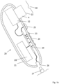
- Fig. 1a shows a schematic representation of a device for stimulating (stimulation device) the clitoris with a variable pressure field in the front view
- Fig. 1b shows the stimulation device in cross section.
- the stimulation device 20 is a, for example, portable, electrical or small device, which has a housing 21, a housing opening 22 for placing on the clitoris 30, controls 23, a display 24, an on/off switch 25, an optional socket 26 and an Battery device 28, for example with an accumulator.
- the housing 21 can be designed ergonomically in such a way that it can be held comfortably with one hand and it has no sharp or pointed edges.
- the housing 21 can consist of a plastic, for example polycarbonate (PC) or acrylonitrile butadiene styrene (ABS).
- PC polycarbonate
- ABS acrylonitrile butadiene styrene
- the grip areas or the entire housing 21 can be supplemented or designed with a tactilely advantageous silicone, for example in the form of a silicone coating.
- the housing 21 can be designed to be at least water-repellent or splash-proof, for example protection class IP 24.
- the stimulation device 20 can be designed to be waterproof against immersion under water.
- the control element 23 or the control elements 23 are used to set the operating mode of the device, ie to set the modulation of the variable pressure field.
- the operating elements 23 can, for example, comprise at least one push button, as at least one rotary switch, or as at least one touch-sensitive switch. Further
- the control elements 23 can provide optical feedback for actuation, for example by means of integrated light-emitting diodes (LED).
- LED integrated light-emitting diodes
- An optional display 24 is used to inform the user about the device status and/or the setting status.
- the display 24 can be designed, for example, with a single light-emitting diode, a plurality of light-emitting diodes or as an LCD display.
- the information displayed can be, for example, the switch-on status of the device, the charge status of the battery device 28 or the current setting of the modulation of the pressure field.
- the on/off switch 25 is used to activate and deactivate the stimulation device 20.
- This on/off switch 25 can be, for example, a push button, which switches the stimulation device 20 on or off when pressed for a longer period of time, or a latching slide switch.
- a socket 26 is used for the external power supply of the stimulation device 20 via an external plug 27, which is connected, for example, to an external power adapter.
- a magnetic-inductive transmitter can be provided instead of the socket 26, which enables power to be transferred into the stimulation device 20 without an electrically conductive contact.
- the stimulation device 20 also has a battery device 28, for example with a rechargeable battery, for example a nickel metal hydrite battery (NiMH) or a lithium battery, for wireless operation.
- a (longer) power supply cable can also be led out of the stimulation device.
- magnetic contacts can be provided as a power supply connection.
- FIG. 1b In the schematic cross section in Fig. 1b the housing opening 22 for placing on the clitoris 30, a pressure chamber 4, and the drive device 32 of the stimulation device 20 are shown.
- a control device 29 controls the drive device 32, the operating elements 23 and the display 24.
- the control device 29 and the drive device 32 are supplied with power from the internal battery device 28 and/or the external power supply 27.
- the control device 29, which has a microcontroller or is hard-wired, for example, initially controls the power supply of all consumers of the stimulation device 20, and optionally a charging and discharging process of the battery device 28 and/or battery management.
- the control device 29 controls the drive unit 32, for example the modulation of the pressure field, etc.
- the control device 29 can have a memory in which at least one modulation or stimulation pattern is stored.
- the drive device 32 can now be controlled in its excitation according to the user's choice of the stimulation device 20 via the control elements 23 in accordance with these pre-stored stimulation patterns.
- the stimulation patterns of the pressure field can optionally be created and saved individually by the user using the controls.
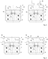
- a displaceable wall section 1 connected to a carrier 5 is moved back and forth in a magnetic field 3 provided by permanent magnets by means of at least one voice or moving coil 2 attached thereto in accordance with a coil supply by means of the control current, so as to move the displaceable wall section 1 during operation to shift back and forth in order to create a variable pressure field.
- the displaceable wall section 1 (for example made of a polymer or paper) as part of a pressure chamber 4 of the stimulation device is attached to a support 5 (for example made of aluminum, Kapton or an aluminum-Kapton laminate).
- the displaceable wall section 1 can be integrated into the chamber via a bead 6, which mechanically follows the strokes of the displaceable wall section 1 largely without mechanical stresses.
- Coil elements of a voice coil 2 are wound around the carrier 5 and are fed during operation by the control current from a control unit.
- the voice coil 2 consists of electrical conductors made of a material that is as electrically conductive as possible (for example copper or silver), which are insulated from each other and from the carrier 5 with an electrically insulating varnish.
- the magnetic field is provided by at least one permanent magnet 7, which can have a ring shape.
- the magnetic flux is generated by means of pole plates 9, which have a rear pole plate 8 (for example, as in Fig. 2 , with a cylindrical shape) and an upper pole plate 9a (for example, as in Fig. 2 , with a ring shape) have, for example, an annular air gap 10 to the cylindrical pole core 11.
- the rear 8 and upper pole plate 9, like the pole core 11, are made of highly magnetically permeable material (for example a soft magnetic material alloy).
- the permanent magnet 7 requires the highest possible flux density in order to induce the air gap 10, which is to be kept as narrow as possible, between the upper pole plate 9a and the pole core 11, which is why the strongest possible permanent magnets with flux densities of approximately 0.5 to approximately 1.2T (for example neodymium-iron-boron -Magnets) are used, which generate strong magnetic fields with low weight.
- the strongest possible permanent magnets with flux densities of approximately 0.5 to approximately 1.2T for example neodymium-iron-boron -Magnets
- the carrier 5 with the voice coil 2 is structurally centered and guided in the air gap 10 by at least one holder or suspension 12 (for example made of plastic, textile fabric or paper) in order to prevent wobbling movements of the voice coil 2.
- the holder or suspension 12 is attached to a frame 13 (for example made of plastic, aluminum or magnesium).
- the voice coil 2 is fed with an alternating control current from a control unit.
- the voice coil 2 is moved up or down by the Lorentz force depending on the current direction or current polarity in the magnetic field of the air gap 10.
- the directions of the Lorentz force, the magnetic field and the current flow are in Fig. 2 perpendicular to each other.
- the stroke of the deflection of the voice coil 2 is determined by the amplitude of the control current.
- the frequency of the alternating current corresponds to the frequency of the voice coil movement and thus the frequency of the movement of the displaceable wall section 1.
- the frequency and the stroke of the voice coil and thus the movement of the displaceable wall section 1 can therefore be controlled comparatively easily by the current frequency and current amplitude independently of one another.
- the changing pressure field and the resulting changing positive and negative pressure on the erogenous body zone are independent in frequency and amplitude due to the changing compression and expansion of the air by means of the movement of the displaceable wall section 1 (or of several displaceable wall sections during operation). controllable from each other.
- alternating current Due to the direct transmission, an extended frequency range from under 1Hz to several hundred Hz is easily possible with this principle.
- the direct current from the accumulator simply needs to be converted into alternating current. Converting to alternating current can involve switching on and off and/or superimposing direct current components include. This allows an alternating voltage with a direct current offset to be provided. For example, an alternating voltage can be provided that does not involve a change in polarity, but rather only a change in the voltage level while the voltage direction (polarity) remains the same.
- the arrangement can be as shown on the right in Fig. 2 have a pressure chamber with a plurality of pressure sub-chambers, in which a further pressure chamber 16 is provided next to the pressure chamber 4, so that connected pressure sub-chambers are provided, which are connected via a connecting channel 15.
- the housing opening for the effect of the variable pressure field on the clitoris is provided on the further pressure chamber 16.
- variable pressure field by moving the displaceable wall section 1 (and thus the excess and negative pressure) is accompanied by the generation of noise, i.e. local pressure fluctuations in the air that propagate at the speed of sound and are perceived by the human ear.
- noise i.e. local pressure fluctuations in the air that propagate at the speed of sound and are perceived by the human ear.
- the noise inherent in the movement of the displaceable wall section 1 can be absorbed by suitable measures, i.e. the sound energy can be converted into heat.
- the noises are dissipated as heat in air according to the absorption principle of a plate vibrator by the friction in at least one of the chamber walls 18, which is formed with another displaceable wall section, and by the friction of the vibrating chamber wall.
- the chamber wall 18, which vibrates to absorb noise is also integrated into the chamber by a resilient spring device 17. Sound energy is also ultimately converted into heat and dissipated by the deformation of the spring and the resulting friction in the spring device 17.
- the plate oscillator is a narrow-band resonance absorber, the mass and spring travel of which must be selected such that the characteristic absorber frequency for the highest possible degree of noise absorption as a function of the sound frequency is as close as possible or in the frequency range of the movement of the displaceable wall section 1.
- the noise caused by the piston or membrane movement should be dissipated into heat in a porous structure according to the absorption principle.
- the chamber walls 18 can be formed with a porous structure and, for example, in integrated into the plate oscillator or alternatively applied to the plate oscillator.
- the noises are absorbed by means of the viscous flow losses of the air due to the friction on the porous damping material and the friction due to the deformation of the material.
- the porous absorber is a broadband absorber, the layer thickness and material of which must be selected such that the characteristic absorber frequency for the highest possible degree of absorption is as close as possible or in the frequency range of the movement of the displaceable wall section 1.
- the drive unit is formed with a few movable components of low weight and therefore has few unbalanced, free mass forces, which stimulate components or the housing of the stimulation device to oscillate or vibrate in certain displaceable wall sections.
- the further displaceable wall section of the chamber wall 18 can optionally be designed with a ferrofluid 14 for damping the resonances of the voice coil 2 and a frame 13 or a closed chamber (not completely filled), which also ensures that the voice coil 2 and carrier 5 are cooled by the increased heat conduction compared to air.
- the heat capacity of the deliberately lightweight voice coil 2 and carrier 5 are low.
- the flexibility in the embodiment of the drive allows a great deal of freedom in the design of the stimulation device, making the drive elongated or wide and also the local pressure fluctuations that propagate at the speed of sound through noise absorption measures in the chamber (cf. Fig. 3 ) to reduce.
- the drive unit or device has a comparatively low complexity due to the direct conversion of the electrical energy of the battery unit 28, for example from the accumulator, into a translational movement of a simple voice coil coupled to the displaceable wall section 1, which in the various versions - regardless of the specific drive -
- a simple voice coil coupled to the displaceable wall section 1, which in the various versions - regardless of the specific drive -
- the direct conversion also results in potentially high efficiency, compact design and low weight.
- the movable wall section(s) 1 can be an integral part of the chamber (Pressure chamber - chamber in which the variable pressure field is generated), which ensures a good seal against compressible and incompressible media up to a certain excess and negative pressure of the chamber.
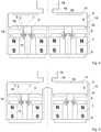
- the displaceable wall section 1 can be used by means of more than one coil 2 and more than one carrier 5, as in Fig. 4 displayed, moved.
- the noises emitted on the back of the displaceable wall section 1 are absorbed, for example, by a device based on the plate oscillator principle or in a porous structure and thereby reduced as much as possible (not shown).
- fine conductors of the coil 2 through which current flows are located directly on at least one movable wall section 1.
- the displaceable wall section 1 there is at least one permanent magnet 7, for example in the form of a bar magnet as in Fig. 6 shown.
- the permanent magnet 7 requires the highest possible flux density in order to induce the air gap 4, which must be kept as narrow as possible, between the permanent magnet 7 and the movable wall section 1 with the electrical conductors 2, which is why the strongest possible permanent magnets with flux densities of 0.5... 1.2T (for example neodymium -Iron-boron magnets) are used, which generate a strong magnetic field 3 with low weight.
- the displaceable wall section 1 (for example made of a polymer or paper) as part of a first chamber of the stimulation device 9 can be integrated into the chamber via a bead 6, which mechanically follows the strokes of the displaceable wall section 1 largely without mechanical stresses.
- the electrical conductors 2 on the movable wall section 1 are made of the most electrically conductive material possible (for example copper or silver) and are electrically insulated from one another by being integrated into the movable wall section 1.
- the magnetic one Flow is controlled by means of side pole plates 19 (for example as in Fig. 6 in rod form) over the air gap 4.
- the side pole plates 19 are made of highly magnetically permeable material (for example a soft magnetic material alloy).
- the chamber of the stimulation device 9, the permanent magnet 7 and the side pole plates 19 are fastened in a frame 8 (for example made of plastic, aluminum or magnesium).
- the thin electrical conductors 2 are fed with an alternating control current from a control unit. Depending on the current direction or current polarity, the electrical conductors 2 are moved up or down in the magnetic field of the air gap 4 by the Lorentz force.
- the driving forces act evenly over the entire surface of the displaceable wall section 1.
- the directions of the Lorentz force, the magnetic field and the current flow are in Fig. 6 perpendicular to each other.
- the electrical conductors via the two permanent magnets 7 must be fed with different polarities in order to cause the same movement.
- the stroke of the deflection of the electrical conductors integrated into the displaceable wall section 1 is determined by the amplitude of the control current.
- the frequency of the alternating current corresponds to the frequency of the conductor movement and thus the frequency of the movement of the displaceable wall section 1.
- the frequency and the stroke of the displaceable wall section 1 can therefore be controlled comparatively easily by the current frequency and current amplitude independently of one another.
- the changing pressure field and the resulting changing positive and negative pressure on the erogenous body zone (clitoris) can be controlled independently of one another in frequency and amplitude by the alternating compression and expansion of the air by means of the movement of the displaceable wall section 1.
- alternating current Due to the direct transmission, an extended frequency range from less than 1Hz to several hundred Hz is easily possible with this principle.
- the direct current from the accumulator simply needs to be converted into alternating current. Converting to alternating current can include switching on and off and/or superimposing direct current components. This allows an alternating voltage with a direct current offset to be provided. For example, an alternating voltage can be provided that does not include a change in polarity, but rather only a change in the voltage level while the voltage direction (polarity) remains the same.
- the drive unit can also be in a ring shape as in Fig. 7 shown can be executed.
- the membrane is circular.
- the permanent magnet 7, the electrical conductors 2, the side pole plate 19 and the holder are designed, for example, in a ring shape.
- a pole core 11 is provided in the axis of symmetry of the drive unit for improved guidance of the magnetic field.
- the drive unit can also be connected to a second chamber 11 via a connecting channel 10, as in Fig. 8 shown.
- At least one second chamber 11 can also be as in Fig. 9 located on the side of the drive unit.
- noise-absorbing devices can be installed according to the plate oscillator principle or in a porous structure as in Fig. 10 be provided.
- the noise-absorbing devices reduce the noise propagation inherent in the movement of the displaceable wall section 1 as much as possible.
- the two-chamber embodiments can be made from Fig. 9 (right) and Fig. 10 (right) can also be designed in ring form.
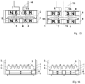
- permanent magnets 7 can alternatively be installed on both sides of the displaceable wall section 1 as in Fig. 12 can be arranged as shown.
- the design of the drive with permanent magnets 7 on both sides of the movable wall section 1 in Fig. 12 can be carried out with two permanent magnets with opposite polarity, each above and below the displaceable wall section 1 (left) or alternatively with two ring-shaped permanent magnets above and below the displaceable wall section 1 (right).
- the noises emitted on the back of the displaceable wall section 1 are absorbed, for example, by a device based on the plate oscillator principle or in a porous structure and thereby reduced as much as possible (not shown).
- the fine conductors 2 through which current flows are located directly on the movable wall section 1, which has at least one thin membrane that is folded in the form of a lamella (lamella membrane).
- the lamellar membrane there is at least one permanent magnet 7 (left), for example in the form of a bar magnet as in Fig. 13 shown.
- the permanent magnet 7 requires the highest possible flux density in order to induce the air gap 4 between the permanent magnet 7 and the lamellar membrane with the electrical conductors 2, which must be kept as narrow as possible, which is why the strongest possible permanent magnets with flux densities of around 0.5 to around 1.2T (for example neodymium Iron-boron magnets) are used, which generate a strong magnetic field 3 with low weight.
- the lamellar membrane (for example made of a polymer such as polyamide, polyester or polyimide) as part of a first chamber of the stimulation device 10 can be integrated into the chamber via a bead 6, which mechanically follows the strokes of the displaceable wall section 1 largely without mechanical stresses.
- the electrically insulated conductors 2 on the lamellar membrane are made of the most electrically conductive material possible (for example copper or silver) and are glued to the lamellar membrane, for example.
- the magnetic flux is controlled by means of side pole plates 19 (for example as in Fig. 13 in rod form) over the air gap 4.
- the side pole plates 19 are made of highly magnetically permeable material (for example a soft magnetic material alloy).
- the chamber of the stimulation device 10, the permanent magnet 7 and the side pole plates 19 are fastened in a frame 9 (for example made of plastic, aluminum or magnesium).
- the lamellar membrane is as in Fig. 13 shown with parallel electrical conductor tracks 2 covered in a meandering shape.
- the direction of current flow must be the same for all conductor tracks, since the magnetic field 3 also has the same orientation everywhere in the air gap 4, which must be kept as narrow as possible in terms of design.
- the electrical conductors 2 are guided in a meandering shape on the lamellar membrane in such a way that the current flows through the adjacent lamellar in the opposite direction.
- the thin electrical conductors 2 are fed with an alternating control current from a control unit.
- the slats move depending on the direction of current flow or polarity
- the Lorentz force then moves towards or away from each other and presses the air out of the space between them or sucks it in.
- the movement of the lamellar membrane can also be achieved with an alternating voltage that does not involve a change in polarity, but rather only a change in the level of voltage while the voltage direction (polarity) remains the same.
- a significantly larger membrane area becomes effective. Despite the comparatively large membrane area, the entire membrane area is driven evenly.
- several permanent magnets 7 in Fig. 13 (right) can be arranged under the lamellar membrane.
- the stroke of the deflection of the electrical conductors 2 integrated into the lamellar membrane is determined by the amplitude of the control current.
- the frequency of the alternating current corresponds to the frequency of the conductor movement and thus the frequency of the lamellar membrane movement.
- the frequency and stroke of the lamellar membrane movement can therefore be controlled comparatively easily by the current frequency and current amplitude independently of one another.
- the changing pressure field and the resulting changing positive and negative pressure on the erogenous body zone (clitoris) can be controlled independently of each other in frequency and amplitude by the alternating compression and expansion of the air by means of the contraction and expansion of the lamellar membrane.
- alternating current Due to the direct transmission, an extended frequency range from under 1Hz to several hundred Hz is easily possible with this principle.
- the direct current from the accumulator simply needs to be converted into alternating current. Converting to alternating current can include switching on and off and/or superimposing direct current components. This allows an alternating voltage with a direct current offset to be provided. For example, an alternating voltage can be provided that does not involve a change in polarity, but rather only a change in the voltage level while the voltage direction (polarity) remains the same.
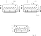
- the drive unit can also be connected to the further chamber 16 via the connecting channel 15, as in Fig. 14 shown.
- At least one second chamber 11 can also be as in Fig. 15 located on the side of the drive unit.
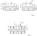
- noise-absorbing devices according to the plate oscillator principle or in a porous structure as in Fig. 16 be provided.
- permanent magnets 7 can alternatively be installed on both sides of the displaceable wall section 1 as in Fig. 17 can be arranged as shown.
- the movable wall section 1 is located in Fig. 17 directly between poles of the permanent magnets 7 and can also be carried out with several permanent magnets 7 next to each other.
- the noises emitted on the back of the lamellar membrane are absorbed, for example, by a device based on the plate oscillator principle or in a porous structure and thereby reduced as much as possible (not shown).
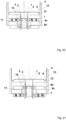
- Fig. 18 to 24 show further exemplary embodiments of an arrangement for a stimulation device or arrangements for the drive unit 32 and the pressure chamber 4.
- coil elements of an electromagnetic linear drive are arranged to be movable or displaceable in a stationary permanent magnetic field.
- the same reference numerals as in the previous figures are used for the same features.
- the suspension or holder 12 which acts as a positioning or centering device for the carrier 5 with the (oscillating) coil 2 is shown in a neutral initial state in which no deflection has taken place.
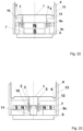
- Fig. 25 and 26 an embodiment in which the carrier 5 with the voice coil 2 from the neutral starting or zero position (cf. Fig. 18 to 24 ) shifted downwards into the stationary permanent magnetic field 3.
- the displaceable chamber wall section 1 is displaced downwards.
- the carrier 5 with the voice coil 2 and the movable chamber wall section 1 then vibrate, starting from the in the Fig. 25 and 26 shown deflected starting position to the neutral rest position.
- especially those in the Fig. 18 to 24 The examples shown are based on the ones in the Fig. 18 to 24 shown neutral rest position swung around this neutral starting position.
- a current of non-changing polarity is provided in other embodiments, for example in one or more of the embodiments in the Fig. 18 to 24 .
- Embodiments shown can be operated during operation around a deflected position that differs from the neutral rest or starting position.
- the coil 2 has an upper partial coil 2a and a lower partial coil 2b with separate coil windings.
- the upper and lower partial coils 2a, 2b are each arranged opposite pole plates 9, with the permanent magnets 7 on the outside ( Fig. 18 ) or inside ( Fig. 19 ) are arranged in relation to the coil 2.
- the internal design supports the formation of optimized magnetic induction.
- the permanent magnets 7 are arranged on the outside in relation to the voice coil 2.
- the arrangement of the permanent magnets 7 shown there, which is compared to the design in the Fig. 18 are arranged instead of the upper pole cap 9a or the lower pole cap 9b, supports a flat design.
- the designs in the Fig. 22 to 24 use one compared to the embodiments in the Fig. 18 to 21 one-piece coil 2, with the permanent magnets 7 also here in relation to the coil 2 according to Fig. 22 and 23 can be arranged inside and outside. When executed in Fig. 24 the permanent magnets 7 are arranged below the voice coil 2.
- a spring 40 is provided, which provides a spring preload against the deflected position of the carrier 5 with the voice coil 2 shown.
- Fig. 26 shows an alternative embodiment in which the spring 40 is omitted.
- a preload can be provided here by means of the suspension/holder 12.
Landscapes
- Health & Medical Sciences (AREA)
- Animal Behavior & Ethology (AREA)
- Pain & Pain Management (AREA)
- Physical Education & Sports Medicine (AREA)
- Rehabilitation Therapy (AREA)
- Life Sciences & Earth Sciences (AREA)
- Epidemiology (AREA)
- General Health & Medical Sciences (AREA)
- Public Health (AREA)
- Veterinary Medicine (AREA)
- Reproductive Health (AREA)
- Percussion Or Vibration Massage (AREA)
- Magnetic Treatment Devices (AREA)
- Reciprocating, Oscillating Or Vibrating Motors (AREA)
Applications Claiming Priority (3)
| Application Number | Priority Date | Filing Date | Title |
|---|---|---|---|
| DE102018107961.3A DE102018107961A1 (de) | 2018-04-04 | 2018-04-04 | Vorrichtung zum Stimulieren der Klitoris mit einem veränderlichen Druckfeld und Verfahren zum Erzeugen eines veränderlichen Druckfelds |
| EP19723636.7A EP3773406B1 (fr) | 2018-04-04 | 2019-04-04 | Dispositif pour stimuler le clitoris avec un champ de pression modulable et procédé pour produire un champ de pression modulable |
| PCT/DE2019/100309 WO2019192661A1 (fr) | 2018-04-04 | 2019-04-04 | Dispositif pour stimuler le clitoris avec un champ de pression modulable et procédé pour produire un champ de pression modulable |
Related Parent Applications (2)
| Application Number | Title | Priority Date | Filing Date |
|---|---|---|---|
| EP19723636.7A Division EP3773406B1 (fr) | 2018-04-04 | 2019-04-04 | Dispositif pour stimuler le clitoris avec un champ de pression modulable et procédé pour produire un champ de pression modulable |
| EP19723636.7A Division-Into EP3773406B1 (fr) | 2018-04-04 | 2019-04-04 | Dispositif pour stimuler le clitoris avec un champ de pression modulable et procédé pour produire un champ de pression modulable |
Publications (3)
| Publication Number | Publication Date |
|---|---|
| EP4342440A2 true EP4342440A2 (fr) | 2024-03-27 |
| EP4342440A3 EP4342440A3 (fr) | 2024-06-12 |
| EP4342440B1 EP4342440B1 (fr) | 2026-02-18 |
Family
ID=66529719
Family Applications (4)
| Application Number | Title | Priority Date | Filing Date |
|---|---|---|---|
| EP24156254.5A Active EP4342440B1 (fr) | 2018-04-04 | 2019-04-04 | Dispositif de stimulation du clitoris avec un champ de pression variable et procédé de production d'un champ de pression variable |
| EP19723636.7A Active EP3773406B1 (fr) | 2018-04-04 | 2019-04-04 | Dispositif pour stimuler le clitoris avec un champ de pression modulable et procédé pour produire un champ de pression modulable |
| EP19787154.4A Active EP3946210B1 (fr) | 2018-04-04 | 2019-09-30 | Dispositif de stimulation d'une zone érogène humaine avec un champ de pression variable |
| EP24195102.9A Active EP4438023B1 (fr) | 2018-04-04 | 2019-09-30 | Dispositif pour stimuler une zone érogène humaine avec un champ de pression variable |
Family Applications After (3)
| Application Number | Title | Priority Date | Filing Date |
|---|---|---|---|
| EP19723636.7A Active EP3773406B1 (fr) | 2018-04-04 | 2019-04-04 | Dispositif pour stimuler le clitoris avec un champ de pression modulable et procédé pour produire un champ de pression modulable |
| EP19787154.4A Active EP3946210B1 (fr) | 2018-04-04 | 2019-09-30 | Dispositif de stimulation d'une zone érogène humaine avec un champ de pression variable |
| EP24195102.9A Active EP4438023B1 (fr) | 2018-04-04 | 2019-09-30 | Dispositif pour stimuler une zone érogène humaine avec un champ de pression variable |
Country Status (9)
| Country | Link |
|---|---|
| US (4) | US12251351B2 (fr) |
| EP (4) | EP4342440B1 (fr) |
| AU (2) | AU2019247064B2 (fr) |
| CA (2) | CA3095965A1 (fr) |
| DE (1) | DE102018107961A1 (fr) |
| DK (2) | DK3773406T3 (fr) |
| ES (2) | ES2981639T3 (fr) |
| FI (2) | FI3773406T3 (fr) |
| WO (2) | WO2019192661A1 (fr) |
Families Citing this family (7)
| Publication number | Priority date | Publication date | Assignee | Title |
|---|---|---|---|---|
| DE202013012252U1 (de) | 2013-09-23 | 2015-11-12 | Novoluto Gmbh | Stimulationsvorrichtung |
| DE202015105689U1 (de) | 2015-03-13 | 2015-11-11 | Novoluto Gmbh | Stimulationsvorrichtung mit Fortsatz |
| DE202016008412U1 (de) | 2016-10-05 | 2017-11-09 | Novoluto Gmbh | Stiftförmige Stimulationsvorrichtung |
| DE102018107961A1 (de) | 2018-04-04 | 2019-10-10 | Novoluto Gmbh | Vorrichtung zum Stimulieren der Klitoris mit einem veränderlichen Druckfeld und Verfahren zum Erzeugen eines veränderlichen Druckfelds |
| EP3685809B2 (fr) | 2019-01-24 | 2025-10-01 | Novoluto GmbH | Dispositif de stimulation pour un pénis humain |
| CN219290098U (zh) * | 2022-12-30 | 2023-07-04 | 深圳市妍爱科技有限公司 | 一种永磁体推动式空气压缩按摩器 |
| US20240238151A1 (en) * | 2023-01-12 | 2024-07-18 | Hytto Pte. Ltd. | Stimulation device for providing sexual stimulation |
Citations (2)
| Publication number | Priority date | Publication date | Assignee | Title |
|---|---|---|---|---|
| DE102013110501A1 (de) | 2013-09-23 | 2015-03-26 | Novoluto Gmbh | Stimulationsvorrichtung |
| DE102016105019B3 (de) | 2016-03-17 | 2017-07-06 | Fun Factory Gmbh | Massagevorrichtung zur Druckwellen-Massage |
Family Cites Families (394)
| Publication number | Priority date | Publication date | Assignee | Title |
|---|---|---|---|---|
| US15626A (en) | 1856-08-26 | Cupping | ||
| US787443A (en) | 1904-01-28 | 1905-04-18 | Emory J Godman | Massaging apparatus. |
| US809810A (en) | 1904-11-29 | 1906-01-09 | John Frederick W Jost | Incandescent gas-lamp. |
| US847360A (en) | 1905-09-25 | 1907-03-19 | Us Standard Electrical Works | Massaging implement. |
| US907749A (en) | 1908-07-29 | 1908-12-29 | Walter D Davenport | Massage-machine. |
| GB191018973A (en) | 1910-08-12 | 1910-11-03 | John Heywood | A New and Improved Pneumatic Appliance for Massage. |
| US1042058A (en) | 1911-01-17 | 1912-10-22 | Kate Van Hook | Massage apparatus. |
| DE278733C (fr) | 1912-08-06 | |||
| US1179129A (en) | 1915-04-27 | 1916-04-11 | Charles W Smith | Suction and compression cupping apparatus. |
| US1378922A (en) | 1919-05-31 | 1921-05-24 | George A Ward | Intermittent-vacuum massage-machine |
| US1502440A (en) | 1922-06-10 | 1924-07-22 | Herbert F Robert | Massaging implement |
| US1762692A (en) | 1927-01-28 | 1930-06-10 | Abraham W Lair | Massage machine |
| US1730535A (en) | 1927-07-25 | 1929-10-08 | Alfred P Rudolph | Hand-operated vacuum massage device |
| US1732310A (en) | 1928-11-01 | 1929-10-22 | Frank J Naibert | Vacuum skin cleanser |
| DE582196C (de) | 1929-07-12 | 1933-08-11 | Johann Boerlage Dr | Einfach wirkende Luftpumpe fuer Massage |
| US1805675A (en) | 1930-01-18 | 1931-05-19 | Alfred P Rudolph | Massage device |
| US1882040A (en) | 1930-03-08 | 1932-10-11 | William A Roehm | Suction-massage apparatus |
| US1898652A (en) | 1930-07-08 | 1933-02-21 | George A Williams | Direct air pulsator |
| US1941665A (en) | 1930-08-06 | 1934-01-02 | Walt Raymond E De | Massage apparatus |
| DE538578C (de) | 1930-08-17 | 1931-11-14 | Henri Robert Hochstrasser | Einrichtung zur wechselweisen Erzeugung von Druck und Unterdruck fuer Heilzwecke |
| US1914290A (en) | 1930-08-26 | 1933-06-13 | Martin E Popkin | Pneumatic massaging and cleansing machine |
| US1998696A (en) | 1931-11-04 | 1935-04-23 | Andis Mathew | Massaging mechanism |
| US1964590A (en) | 1931-11-28 | 1934-06-26 | Muller Friederich | Vibrator |
| US2052098A (en) | 1934-04-14 | 1936-08-25 | Andrew M Lockett | Therapeutic vibrator |
| US2017284A (en) | 1934-04-16 | 1935-10-15 | Walter E Lembright | Massaging device |
| US2076410A (en) | 1935-04-08 | 1937-04-06 | Automatic Musical Instr Co | Massage instrument |
| US2064418A (en) | 1935-08-20 | 1936-12-15 | Knapp Monarch Co | Electric vibrator |
| US2154427A (en) | 1935-10-29 | 1939-04-18 | Automatic Instr Company | Electric vibrator |
| US2112646A (en) | 1936-08-10 | 1938-03-29 | Biederman Joseph Bear | Device for the treatment of diseases of the genital organs |
| US2218081A (en) | 1937-03-27 | 1940-10-15 | Brichieri-Colombi Luigi | Massage device |
| US2234102A (en) | 1937-04-26 | 1941-03-04 | Automatic Instr Company | Vibrator |
| US2189116A (en) | 1939-07-26 | 1940-02-06 | Harriette E Niemiec | Massage device |
| US2218443A (en) | 1939-09-14 | 1940-10-15 | Tweddle David | Massage apparatus |
| US2314590A (en) | 1940-08-26 | 1943-03-23 | John D Grey | Electrovacuum vibrator |
| US2470660A (en) | 1945-04-07 | 1949-05-17 | Knapp Monarch Co | Electric vibrator |
| US2519790A (en) | 1948-12-09 | 1950-08-22 | William H Quinn | Massaging apparatus |
| US2561034A (en) | 1949-03-19 | 1951-07-17 | Arlis F Phillips | Combination vibrator and vacuum massage device |
| DE856788C (de) | 1949-10-12 | 1952-11-24 | Wolfgang Wehl | Saug-Druck-Wechselmassageapparat |
| US2616417A (en) | 1950-05-23 | 1952-11-04 | Louis S Holbrook | Device for massaging by means of air suction |
| US2674994A (en) | 1952-06-19 | 1954-04-13 | Owen K Murphy | Motor operated kinesitherapy device |
| US2661736A (en) | 1952-08-20 | 1953-12-08 | Republic Electric & Mfg Corp | Electric vibrator for massage purposes |
| DE1703184U (de) | 1954-02-06 | 1955-07-21 | Hermann Rohling & Co K G | Vacuum-massagegeraet. |
| CH329193A (de) | 1954-07-24 | 1958-04-15 | Maurice Dr Med Fuchs | Massagevorrichtung |
| DE1463673A1 (de) | 1963-11-08 | 1969-03-27 | Standard Elek K Lorenz Ag | Schaltungsanordnung zur Gleichlastregelung |
| GB1049973A (en) | 1964-06-30 | 1966-11-30 | Leo Entpr Ltd | Improvements in or relating to massage vibrators |
| GB1077143A (en) | 1964-09-30 | 1967-07-26 | Norman Alexander Macleod | Improvements in an applicator for use in the therapeutic treatment of skin |
| US3396720A (en) | 1964-10-30 | 1968-08-13 | Ohkubo Shigeyuki | Cosmetic massage device |
| GB1060507A (en) | 1965-05-13 | 1967-03-01 | Kot Pak Sang | Vibrator |
| JPS4728781Y1 (fr) | 1967-06-02 | 1972-08-30 | ||
| FR2072609A5 (fr) | 1969-12-01 | 1971-09-24 | Kawada Sohji | |
| US3619673A (en) * | 1970-04-07 | 1971-11-09 | Data Products Corp | Moving coil linear motor |
| DE7237890U (de) | 1972-10-16 | 1973-03-15 | Hueckel H | Massagestab |
| US3841323A (en) | 1973-07-23 | 1974-10-15 | D Stoughton | Massage apparatus |
| US3906940A (en) | 1974-08-26 | 1975-09-23 | Sohji Kawada | Facial treatment device |
| US3910262A (en) | 1974-11-04 | 1975-10-07 | Dan T Stoughton | Therapeutic apparatus |
| GB1513605A (en) | 1975-09-04 | 1978-06-07 | Mabuchi Motor Co | Beauty treatment device |
| JPS547433Y2 (fr) | 1976-05-24 | 1979-04-06 | ||
| US4033338A (en) | 1976-06-04 | 1977-07-05 | Kingsley Igwebike | Vibratory feminine hygiene vacuum device |
| JPS53135768A (en) | 1977-04-30 | 1978-11-27 | Matsushita Electric Works Ltd | Face treating apparatus |
| JPS5927576B2 (ja) | 1977-05-06 | 1984-07-06 | 松下電工株式会社 | 美顔器 |
| JPS53149442A (en) | 1977-05-31 | 1978-12-26 | Matsushita Electric Works Ltd | Cosmetic device |
| US4232661A (en) | 1978-02-08 | 1980-11-11 | Christensen Earl A | Body massage apparatus |
| JPS594135B2 (ja) | 1978-02-28 | 1984-01-27 | 松下電工株式会社 | 吸引型美顔器のフィルタ装置 |
| US4175554A (en) | 1978-03-16 | 1979-11-27 | Gerow Frank J | Prosthesis of male impotence |
| US4318038A (en) * | 1978-11-15 | 1982-03-02 | Nippon Electric Co., Ltd. | Moving-coil linear motor |
| US4312350A (en) | 1979-08-23 | 1982-01-26 | Doan Rosetta C | Apparatus for collecting seminal fluids |
| US4612592A (en) * | 1979-12-26 | 1986-09-16 | Burroughs Corporation | Dual coil/dual magnet actuator |
| US4428368A (en) | 1980-09-29 | 1984-01-31 | Masakatsu Torii | Massage device |
| JPS6041956B2 (ja) | 1980-12-10 | 1985-09-19 | 松下電工株式会社 | 電気かみそりのトリマ装置 |
| US4439699A (en) * | 1982-01-18 | 1984-03-27 | International Business Machines Corporation | Linear moving coil actuator |
| GB2137097A (en) | 1983-03-28 | 1984-10-03 | Kam Weng Tong | Sexual Intercourse Aid |
| DE3515691A1 (de) | 1985-05-02 | 1986-02-27 | Günter 2071 Siek Straten | Saugstossmassagemaschine (fuer den unterleib) |
| KR900005760B1 (ko) * | 1986-02-19 | 1990-08-09 | 가부시기가이샤 히다찌 세이사꾸쇼 | 가동코일형 리니어 모터 |
| JPS62231663A (ja) | 1986-04-01 | 1987-10-12 | 林原 健 | 振動刺激装置 |
| JPS63102758A (ja) | 1986-10-18 | 1988-05-07 | 株式会社 アズ・インタ−ナシヨナル | 肌用吸引式クリ−ナ |
| FR2627693B1 (fr) | 1988-02-26 | 1991-06-28 | Romain Michel | Appareil electromagnetique pour traitements medicaux par stimulations vibratoires locales |
| JPH0636819Y2 (ja) | 1988-10-15 | 1994-09-28 | 鐘紡株式会社 | 吸引器 |
| USD323034S (en) | 1990-01-12 | 1992-01-07 | Conair Corporation | Therapeutic massager or the like |
| USD329563S (en) | 1990-05-07 | 1992-09-22 | Vectra Fitness, Inc. | Storage rack for dumbbells |
| DE9011708U1 (de) | 1990-08-11 | 1990-10-18 | Kainka, Silvia, 2000 Hamburg | Massagevorrichtung für Körperhöhlen |
| EP0503027B1 (fr) | 1990-10-01 | 1995-04-12 | BAGNOUD, Marius | Appareil pour le drainage lymphatique |
| RU2014059C1 (ru) | 1991-03-14 | 1994-06-15 | Владимир Леонидович Муранивский | Оргастический пояс с комплектом насадок |
| US5127396A (en) | 1991-05-30 | 1992-07-07 | Health Devices Corporation | Plug and phallic device and system |
| US5440183A (en) * | 1991-07-12 | 1995-08-08 | Denne Developments, Ltd. | Electromagnetic apparatus for producing linear motion |
| JPH0537234A (ja) | 1991-07-26 | 1993-02-12 | Nec Corp | 誘電体発振器 |
| JP2555943Y2 (ja) | 1991-10-28 | 1997-11-26 | 紀伊産業株式会社 | 吸引器 |
| USD351236S (en) | 1992-01-10 | 1994-10-04 | Metronic Electronic Gmbh | Combined heat massager and receptacle |
| CN1056276C (zh) | 1992-03-23 | 2000-09-13 | 方存云 | 吻式美容器 |
| CN2153351Y (zh) | 1992-10-22 | 1994-01-19 | 管程霄 | 气体保健按摩器 |
| US5336158A (en) | 1992-11-12 | 1994-08-09 | Huggins Freddie L | Pneumatic vacuum vibrator apparatus |
| DE4243876A1 (de) | 1992-12-23 | 1994-06-30 | Michael Lenke | Gerät zur Hautbehandlung sowie Verfahren zur kosmetischen Hautbehandlung |
| DE4304091C2 (de) | 1993-02-11 | 1995-04-13 | Frenkel Gmbh | Massagegerät |
| JP2739090B2 (ja) | 1993-04-15 | 1998-04-08 | 株式会社ビバリーコーポレーション | 美容器 |
| DE9309994U1 (de) | 1993-04-30 | 1993-10-07 | Lenke, Michael, 94526 Metten | Massagegerät |
| CN2157772Y (zh) | 1993-06-04 | 1994-03-02 | 王兆源 | 正负气压肢体治疗仪的气压发生装置 |
| JP2555943B2 (ja) | 1993-08-06 | 1996-11-20 | 日本電気株式会社 | 半導体装置の製造方法 |
| US5501650A (en) | 1993-09-08 | 1996-03-26 | Gellert; Reinhard R. | Automated masturbatory device |
| DE4341790A1 (de) | 1993-12-08 | 1995-06-14 | Liebig Otto | Pneumatisch regulierbare Potenzstütze |
| USD359563S (en) | 1994-03-28 | 1995-06-20 | Jimmy Chi | Massager |
| CN2198900Y (zh) | 1994-07-22 | 1995-05-31 | 刘剑虹 | 便携通络治疗器 |
| US5593381A (en) | 1994-07-25 | 1997-01-14 | Neptune Pundak & Ayalon Ltd. | Skin and tissue treatment and stimulation device and method |
| WO1996011767A1 (fr) | 1994-10-18 | 1996-04-25 | Emhart Inc. | Dispositif a souder des goujons |
| DE19505047C1 (de) | 1995-02-15 | 1997-01-09 | Gemicon Gmbh | Therapiegerät |
| US5647837A (en) | 1995-03-30 | 1997-07-15 | Mccarty; Donald L. | Tumescence sustaining applicator |
| US5725473A (en) | 1995-08-28 | 1998-03-10 | Taylor; Larry Thornell | Sexual aid |
| US5690603A (en) | 1995-09-25 | 1997-11-25 | Kain; Melissa Mia | Erogenic stimulator |
| US5662593A (en) | 1995-12-22 | 1997-09-02 | T. Top (1994) Ltd. | Massaging appliance and cream dispenser unit therefor |
| FR2746639B1 (fr) | 1996-04-01 | 1998-07-10 | Grea Alain | dispositif de massage pneumatique local de la peau par variation de pression d'air relative positive et negative en enceinte fermee |
| DE19615557A1 (de) | 1996-04-19 | 1997-10-23 | Hans Wellhausen | Vibrations-Massage-Gerät |
| US5813973A (en) | 1996-05-30 | 1998-09-29 | Gloth; David | Device and method for alleviating female urinary incontinence |
| US5693002A (en) | 1996-09-16 | 1997-12-02 | Topco Sales | Sexual appliance having a suction device which provides stimulation |
| USD402905S (en) | 1997-08-27 | 1998-12-22 | Matsushita Electric Industrial Co., Ltd. | Electronic clinical thermometer |
| USD414582S (en) | 1997-11-28 | 1999-09-28 | Hyeon-Bae Hwang | Skin beauty apparatus |
| JP3324990B2 (ja) | 1998-01-14 | 2002-09-17 | 松下電工株式会社 | 美顔器 |
| DE29809041U1 (de) | 1998-05-19 | 1998-11-05 | Szwajcowski, Monika, 26160 Bad Zwischenahn | Gummi-Saugglocke für Akupunktur und Massage manuell bedienbar |
| DE29809828U1 (de) | 1998-06-02 | 1998-11-12 | Bossert, Matthias, 63927 Bürgstadt | Vibrierende Komponente zum Einsatz im Bereich der sexuellen Stimulation |
| KR100476041B1 (ko) | 1998-06-23 | 2005-07-07 | 비오이 하이디스 테크놀로지 주식회사 | 액정 패널과 테이프 캐리어 패키지 연결 구조 |
| US6099463A (en) | 1998-08-03 | 2000-08-08 | Hockhalter; Robert | Female stimulator comprising close-fitting clitoral suction chamber |
| TW558982U (en) | 1998-10-26 | 2003-10-21 | Matsushita Electric Works Ltd | Facial aesthetic treatment apparatus |
| US6964643B2 (en) | 1998-11-18 | 2005-11-15 | Nugyn, Inc. | Devices and methods for treatment of incontinence |
| WO2000028939A2 (fr) | 1998-11-18 | 2000-05-25 | Urometrics, Inc. | Dispositifs et procedes servant a traiter le clitoris |
| DE19853353C2 (de) | 1998-11-19 | 2002-05-02 | Hubertus Bordfeld | Vorrichtung zum Entfernen von Insektenstichen |
| US6666875B1 (en) | 1999-03-05 | 2003-12-23 | Olympus Optical Co., Ltd. | Surgical apparatus permitting recharge of battery-driven surgical instrument in noncontact state |
| US7104950B2 (en) | 1999-07-02 | 2006-09-12 | Th, Inc. | Sexual stimulation |
| WO2001058393A1 (fr) | 2000-02-11 | 2001-08-16 | Potencia Medical Ag | Appareil de traitement de l'impuissance avec unite de transformation d'energie |
| USD443057S1 (en) | 2000-02-18 | 2001-05-29 | Urometrics, Inc. | Clitoral therapy device |
| DE10011289A1 (de) | 2000-03-08 | 2001-09-20 | Sven Harzbecker | Vorrichtung zur Reinigung der Haut |
| CN1116064C (zh) | 2000-12-15 | 2003-07-30 | 刘周鲁鄂 | 治疗骨质增生的药物 |
| DE10100795A1 (de) | 2001-01-10 | 2002-08-14 | Braun Gmbh | Aufladbares Elektrogerät, Ladestation für ein solches Elektrogerät und Verfahren zur Datenübertragung zwischen einem solchen Elektrogerät und einer Ladestation hierfür |
| DE20106065U1 (de) | 2001-03-30 | 2001-11-08 | Kadri, Asis, 13125 Berlin | Massagestab mit integrierter Nachtsichtkamera |
| USD463862S1 (en) | 2001-05-31 | 2002-10-01 | Specialife Industries Ltd. | Water massager |
| US6517511B2 (en) | 2001-06-22 | 2003-02-11 | Tzu-Chiang Yao | Cleansable multi-purpose nasal discharge aspirator |
| US6758826B2 (en) | 2001-07-03 | 2004-07-06 | Water Pik, Inc. | Vibrating personal massager |
| DE20112384U1 (de) | 2001-07-27 | 2001-10-31 | W.+ W. Frenkel GmbH & Co. KG, 72514 Inzigkofen | Massage-Saugglocke für Schwing-Massagegeräte |
| US20040260209A1 (en) | 2003-06-23 | 2004-12-23 | Engli (2001) Ltd. | System and method for face and body treatment |
| US20040260210A1 (en) | 2003-06-23 | 2004-12-23 | Engii (2001) Ltd. | System and method for face and body treatment |
| CN100434058C (zh) | 2001-12-17 | 2008-11-19 | 皇家飞利浦电子股份有限公司 | 带有至少两个吸嘴的个人护理设备 |
| US6723060B2 (en) | 2002-02-07 | 2004-04-20 | Edward W. Miller | Vibrator |
| US20030176817A1 (en) | 2002-03-12 | 2003-09-18 | Shun-Yi Chang | Electrical multi-functional fitness and body slimming massage device |
| DE10218124B4 (de) | 2002-04-23 | 2004-07-15 | Siemens Ag | Ladevorrichtung zur kontaktlosen Ladung batteriebetriebener Geräte |
| US7318811B1 (en) | 2002-06-03 | 2008-01-15 | Charles Corbishley | Vibrating body jewelry device |
| DE10392886B4 (de) | 2002-07-09 | 2007-12-06 | Kyung-Sam Byon | Tragbarer elektronischer peniler Gefässerweiterer |
| US8308631B2 (en) | 2002-10-17 | 2012-11-13 | Kobashikawa Alvin Y | Electronic variable stroke devices and system for remote control and interactive play |
| USD478385S1 (en) | 2002-11-04 | 2003-08-12 | Wahl Clipper Corporation | Massager |
| US7079898B2 (en) | 2002-11-25 | 2006-07-18 | Salomon Cohn | Pain relieving and healing device |
| US6733438B1 (en) | 2002-12-23 | 2004-05-11 | Jeffrey Dann | Female stimulation device |
| US6976970B2 (en) | 2003-03-24 | 2005-12-20 | Health Devices Corporation | Hub assembly for simultaneously mounting plural vibrating devices |
| ITBO20030186A1 (it) | 2003-04-01 | 2004-10-02 | Gen Project Srl | Apparecchiatura per il massaggio cutaneo. |
| EP1477149B1 (fr) | 2003-05-14 | 2009-07-22 | Rocks off Limited | Dispositif d'aide de stimulation |
| US7258675B2 (en) | 2003-05-21 | 2007-08-21 | Thomas Nichols | Facial rejuvenation device and method |
| JP4075001B2 (ja) | 2003-06-17 | 2008-04-16 | ドクタース テック カンパニー リミティッド | 皮膚美容装置 |
| TW595494U (en) | 2003-06-26 | 2004-06-21 | Biboting Int Co Ltd | Underbelly exercise device |
| AU156617S (en) | 2003-07-25 | 2004-10-08 | Lrc Products | Stimulation device |
| WO2005061042A1 (fr) | 2003-12-18 | 2005-07-07 | Cms Co., Ltd. | Appareil d'impregnation sous vide pour la croissance et la repousse des cheveux |
| USD510441S1 (en) | 2004-01-06 | 2005-10-04 | Brookstone Purchasing, Inc. | Massager |
| JP2005198988A (ja) | 2004-01-19 | 2005-07-28 | Matsushita Electric Works Ltd | 美顔器 |
| JP3991990B2 (ja) | 2004-01-19 | 2007-10-17 | 松下電工株式会社 | 美顔器 |
| JP3952021B2 (ja) | 2004-01-19 | 2007-08-01 | 松下電工株式会社 | 美顔器 |
| JP4109640B2 (ja) | 2004-02-25 | 2008-07-02 | 株式会社エム・アイ・ラボ | 自動励振マッサージ器 |
| US7824351B2 (en) | 2004-03-05 | 2010-11-02 | David Heilman | Feminine hydro-therapeutic massage device |
| US20090038069A1 (en) | 2004-03-05 | 2009-02-12 | David Heilman | Hydro-therapeutic massage device |
| US8100887B2 (en) | 2004-03-09 | 2012-01-24 | Bluesky Medical Group Incorporated | Enclosure-based reduced pressure treatment system |
| JP2005288079A (ja) | 2004-03-31 | 2005-10-20 | Nippori Gift:Kk | 性感帯開発鍛練具 |
| WO2005099366A2 (fr) | 2004-04-05 | 2005-10-27 | Christopher Kargula | Dispositif de simulation de l'acte sexuel |
| CN2696611Y (zh) | 2004-04-06 | 2005-05-04 | 崔新军 | 吸附式按摩器 |
| DE102004017702A1 (de) | 2004-04-10 | 2005-10-27 | Kannengießer, Wilhelm | Intimsaugschale mit Einführsonde |
| US8147399B2 (en) | 2004-05-11 | 2012-04-03 | Gloth David A | Device and method for applying a biocompatible substance to a female stimulation device |
| US6949067B1 (en) | 2004-05-11 | 2005-09-27 | Dann Jeffrey A | Device and method for enhancing female sexual stimulation |
| US20050273024A1 (en) | 2004-06-04 | 2005-12-08 | Nanma Manufacturing Co., Ltd. | Bendable vibrator device |
| USD523562S1 (en) | 2004-09-24 | 2006-06-20 | Plum Tree Uk Ltd. | Vibrator |
| USD523561S1 (en) | 2004-09-24 | 2006-06-20 | Plum Tree Uk Ltd. | Vibrator |
| USD523963S1 (en) | 2004-09-24 | 2006-06-27 | Plum Tree Uk Ltd. | Vibrator |
| ES2251885B1 (es) | 2004-10-29 | 2007-07-16 | Invenciones Medico Sanitarias, S.L. | Dispositivo incentivador del placer sexual. |
| US7588533B2 (en) | 2004-11-26 | 2009-09-15 | Joanne Drysdale | Sexual therapy device |
| CA2491249A1 (fr) | 2004-12-17 | 2006-06-17 | Bruce Murison | Dispositif de stimulation sexuelle electromecanique |
| CN2765609Y (zh) | 2004-12-21 | 2006-03-22 | 周学谦 | 电子按摩治疗仪 |
| DE202005004843U1 (de) | 2005-03-17 | 2005-07-14 | Merlaku, Kastriot | Vibrator |
| DE102005042092B4 (de) | 2005-03-17 | 2021-06-17 | Kastriot Merlaku | Vibrator für Erotik-Zwecke zum Einführen in eine Vagina |
| US7261685B2 (en) | 2005-04-12 | 2007-08-28 | Wu Chang Jy Richard | On-genital erection device and system for coital use |
| US20070100259A1 (en) | 2005-11-02 | 2007-05-03 | Nanma Manufacturing Co. Ltd. | Massage apparatus |
| USD613417S1 (en) | 2005-12-09 | 2010-04-06 | Jimmyjane, Inc. | Vibrating massager |
| US9132058B2 (en) | 2006-02-01 | 2015-09-15 | LELO Inc. | Rechargeable personal massager |
| CA2535276A1 (fr) | 2006-02-06 | 2007-08-06 | John Kennedy | Dispositif therapeutique et systeme et methode pour reduire l'exposition nocive au rayonnement electromagnetique |
| DE102006016401B3 (de) | 2006-04-07 | 2007-08-30 | Witt, Florian M. | Kupplung zweier Fluidleitungsenden mit Halbkugelabschnitten |
| WO2007119034A1 (fr) | 2006-04-13 | 2007-10-25 | Libertybelle Marketing Ltd | Masseur de prostate/dispositif d'assistance sexuelle a glissement « main libre » |
| US20080011310A1 (en) | 2006-05-03 | 2008-01-17 | Gt Urological, Llc | External penile compression cuff with absorbent pouch |
| KR20090034925A (ko) | 2006-06-27 | 2009-04-08 | 팔로마 메디칼 테크놀로지스, 인코포레이티드 | 핸드헬드 광미용 장치 |
| EP2059210B1 (fr) | 2006-08-30 | 2019-05-01 | Ohmea Medical Technologies, LLC | Dispositifs thérapeutiques pour le traitement de divers états chez la femme |
| US20080119913A1 (en) | 2006-10-26 | 2008-05-22 | Lumiport, Llc | Light therapy personal care device |
| US20080106896A1 (en) | 2006-11-03 | 2008-05-08 | Biboting International Co., Ltd. | Illumination device for coupling with cup structure |
| JP2008125577A (ja) | 2006-11-17 | 2008-06-05 | Eisuke Imanaga | 薬効成分送達システム、施術用カップ及び薬効成分含有組成物 |
| KR200439531Y1 (ko) | 2006-12-18 | 2008-04-17 | 연성흠 | 불감증치료용 팽창기구 |
| USD545446S1 (en) | 2007-01-26 | 2007-06-26 | Zhejiang Lover Health Science And Technology Development Co., Ltd. | Control device |
| US7534203B2 (en) | 2007-02-05 | 2009-05-19 | Placeo | Vibrator device with inflatable, alterable accessories |
| WO2009087627A2 (fr) | 2008-01-08 | 2009-07-16 | Placeo | Dispositif de stimulation |
| US20090275796A1 (en) | 2007-02-05 | 2009-11-05 | Noam Gil | Stimulation device |
| WO2008107902A2 (fr) | 2007-03-07 | 2008-09-12 | Galmedics Biotech Ltd. | Dispositifs, systèmes et procédés permettant de raccourcir la durée des menstruations |
| US7824363B2 (en) | 2007-05-04 | 2010-11-02 | Medela Holding Ag | Hands-free breast pump with balanced reciprocating drive |
| US20080304984A1 (en) | 2007-06-08 | 2008-12-11 | Man-Yan Chan | Therapeutic device |
| CN201067499Y (zh) | 2007-06-13 | 2008-06-04 | 陈民欣 | 手持式治疗装置 |
| TW200848010A (en) | 2007-06-15 | 2008-12-16 | Avita Corp | Nose vacuum device |
| WO2009012172A2 (fr) | 2007-07-13 | 2009-01-22 | Finger-Fitting Products, Inc. | Appareil de massage programmable portable |
| US20090016563A1 (en) * | 2007-07-14 | 2009-01-15 | Aurasound, Inc. | Micro-speaker |
| US8100886B2 (en) | 2007-08-15 | 2012-01-24 | Visiomed Group Sa | Aspirator assembly |
| CN201101685Y (zh) | 2007-09-18 | 2008-08-20 | 碧波庭国际有限公司 | 健胸仪器 |
| JP4400665B2 (ja) | 2007-09-28 | 2010-01-20 | パナソニック電工株式会社 | 超音波美容器具 |
| US7828717B2 (en) | 2007-10-08 | 2010-11-09 | Wing Pow International Corp. | Mechanized dildo |
| WO2010042045A1 (fr) | 2008-10-10 | 2010-04-15 | Milux Holding S.A. | Système, appareil et procédé de traitement de patiente à dysfonctionnement sexuel |
| US20090118573A1 (en) | 2007-11-05 | 2009-05-07 | Min-Hao Tsao | Vacuum suction cup |
| DE202007019339U1 (de) | 2007-11-13 | 2011-12-01 | Dieter Olpp | Elektrische Zahnbürste mit zugehöriger Ladestation |
| DE202007016874U1 (de) | 2007-11-30 | 2008-02-14 | Msp Concept Gmbh & Co. Kg | Haltevorrichtung für ein Penisextensionsgerät |
| CN201119979Y (zh) | 2007-12-07 | 2008-09-24 | 邢秀龙 | 振吸式电动按摩器 |
| CN201139737Y (zh) | 2008-01-18 | 2008-10-29 | 杨晓川 | 一种电动吸吹式美容仪 |
| US7530944B1 (en) | 2008-03-14 | 2009-05-12 | Melissa Mia Kain | Erogenic stimulator |
| US10441764B2 (en) | 2008-06-09 | 2019-10-15 | Robert E. Akridge | Sonic applicator for skin formulations |
| US10219974B2 (en) | 2008-06-16 | 2019-03-05 | Udo Blenk | Massage device |
| US9107797B2 (en) | 2008-08-11 | 2015-08-18 | Tricatalyst, Llc | Sexual stimulation devices and methods |
| US8647255B2 (en) | 2008-08-11 | 2014-02-11 | Tricatalyst, Llc | Sexual stimulation devices and methods |
| CN101401739A (zh) | 2008-08-22 | 2009-04-08 | 东莞市雅思电子有限公司 | 一种电动黑头清洁器的负压装置 |
| USD612510S1 (en) | 2008-09-08 | 2010-03-23 | Brookstone Purchasing, Inc. | Light therapy wand |
| AU2009292907A1 (en) | 2008-09-19 | 2010-03-25 | John De Alva | Sexual aid system |
| AU2009303298B2 (en) | 2008-10-10 | 2013-05-23 | Internet Services, Llc | Haptic output device for use with haptic encoded media |
| NO329077B1 (no) | 2008-11-21 | 2010-08-16 | Vibrotron As | Fremgangsmate og anordning for ereksjonsforsterkning |
| USD621950S1 (en) | 2008-12-19 | 2010-08-17 | Panasonic Electric Works Co., Ltd. | Light irradiation facial apparatus |
| USD652523S1 (en) | 2009-01-07 | 2012-01-17 | Kate Somerville Skin Care, LLC | Skin care device |
| KR101026295B1 (ko) | 2009-02-18 | 2011-03-31 | 장태순 | 마사지장치용 이중 구조 마사지 컵 |
| USD609361S1 (en) | 2009-05-12 | 2010-02-02 | The Gillette Company | Laser hand piece |
| TWM377220U (en) | 2009-05-19 | 2010-04-01 | Biboting Int Co Ltd | Mask used for physical therapy |
| WO2010149168A1 (fr) | 2009-06-25 | 2010-12-29 | Ingeniørhøjskolen I Århus | Diffuseur extensible |
| KR20120056854A (ko) | 2009-08-26 | 2012-06-04 | 지미제인, 인코포레이티드 | 가요성 하부구조체를 가진 마사지장치 |
| JP2011083423A (ja) | 2009-10-15 | 2011-04-28 | Panasonic Electric Works Co Ltd | 生体用刺激付与装置 |
| US20110098613A1 (en) | 2009-10-23 | 2011-04-28 | Minna Life Llc | Massage Device and Control Methods |
| US9295572B2 (en) | 2010-03-04 | 2016-03-29 | Kelsey MacKenzie Stout | Shared haptic device with sensors for in-situ gesture controls |
| USD637309S1 (en) | 2010-03-05 | 2011-05-03 | Youn Hoon Park | Beauty massager |
| USD666303S1 (en) | 2010-03-05 | 2012-08-28 | Jane Jian Ding | Massage apparatus |
| US8308667B2 (en) | 2010-03-12 | 2012-11-13 | Wing Pow International Corp. | Interactive massaging device |
| JP2011188921A (ja) | 2010-03-12 | 2011-09-29 | Panasonic Electric Works Co Ltd | 振動付与装置 |
| US20110230802A1 (en) | 2010-03-16 | 2011-09-22 | Nanma Manufacturing Co., Ltd. | Massage device with magnetic field effect control capabilities |
| EP2412392A1 (fr) | 2010-07-29 | 2012-02-01 | Koninklijke Philips Electronics N.V. | Pompe à piston avec tampon variable |
| CA139448S (en) | 2010-09-10 | 2011-10-13 | Lrc Products | Stimulation device |
| DE202010012572U1 (de) | 2010-09-28 | 2011-05-26 | Canbulat, Okay, 30823 | Der Länge nach umfangvergrößernder Teilummantelungsaufsatz aus Silikon mit integrierter Vibrationsfunktion für den menschlichen Penis-(Sextoy) |
| FI123981B (fi) | 2010-12-01 | 2014-01-15 | Hld Healthy Life Devices Oy | Pulsaatiohierontalaite |
| US20120150076A1 (en) | 2010-12-13 | 2012-06-14 | Wayne Clarvoe | Equalizer suction/ vibrator & satisfaction guarantee |
| CN202154785U (zh) | 2010-12-31 | 2012-03-07 | 郝新明 | 阳具形系列安全套 |
| USD670398S1 (en) | 2011-01-06 | 2012-11-06 | InControl Medical, LLC | Stimulation device |
| US9987190B2 (en) | 2011-03-04 | 2018-06-05 | Kelsey MacKenzie Stout | Shared cybernetics using gestures |
| USD649657S1 (en) | 2011-03-29 | 2011-11-29 | Brookstone Purchasing, Inc. | Hand-held massager with a plurality of attachable node assemblies |
| WO2012152297A1 (fr) | 2011-05-09 | 2012-11-15 | Gabriel Welle | Appareil de massage pour stimulation sexuelle |
| KR101305550B1 (ko) | 2011-12-15 | 2013-09-06 | 홍상현 | 역류 방지 기능을 갖는 모유 착유기용 펌핑 장치 및 이를 적용한 모유 착유기 |
| LT2726048T (lt) | 2011-07-01 | 2017-02-10 | Standard Innovation Corporation | Seksualinės stimuliacijos įrenginys |
| US8870746B2 (en) | 2011-07-07 | 2014-10-28 | Courtney A. Carlson | Female stimulation device |
| US20130060081A1 (en) | 2011-09-01 | 2013-03-07 | Catherine Ann Carter | Segmented massage system |
| CN103796619B (zh) | 2011-09-08 | 2016-10-12 | 罗纳尔多·艾伦·布朗 | 用于促进阴茎疲软的男性的性高潮的装置 |
| US8382656B1 (en) | 2011-09-08 | 2013-02-26 | Ronald Allen Brown | Apparatus and method for facilitating male orgasm |
| EP2758012B1 (fr) | 2011-09-22 | 2017-11-15 | Swiss-Tec Global Limited | Raccord à vide pour un appareil d'extension du pénis |
| CN104203191A (zh) | 2011-10-26 | 2014-12-10 | Jj探测有限责任公司 | 用于个人按摩的系统、设备和方法 |
| WO2013067367A1 (fr) | 2011-11-04 | 2013-05-10 | Ohmera Medical Technologies, Inc. | Systèmes et méthodes de traitements thérapeutiques de différentes affections chez la femme |
| ES2407459B1 (es) | 2011-11-11 | 2013-12-26 | E-Process Consulting And Management 2013, S.L. | Dispositivo para la estimulación sexual femenina. |
| USD750301S1 (en) | 2011-11-15 | 2016-02-23 | Fluke Corporation | Strobe light |
| USD671226S1 (en) | 2012-02-27 | 2012-11-20 | Wahl Clipper Corporation | Massager housing |
| EP2823377A4 (fr) | 2012-03-06 | 2016-01-06 | Coactive Drive Corp | Ensemble synchronisé d'actionneurs à vibration dans une topologie de réseau |
| CN202715029U (zh) | 2012-03-06 | 2013-02-06 | 胡智强 | 气囊式震动按摩器 |
| US20130237751A1 (en) | 2012-03-07 | 2013-09-12 | Taylor Lawrence Alexander | Linear Motor and Handheld Unit |
| WO2013138658A1 (fr) | 2012-03-14 | 2013-09-19 | Zipper Ralph | Dispositif de stimulation sexuelle amélioré utilisant la photothérapie et la vibration |
| CN102600034B (zh) | 2012-04-20 | 2013-10-23 | 爱侣健康科技有限公司 | 头部带震动的转珠按摩棒 |
| US10328184B2 (en) | 2012-05-08 | 2019-06-25 | John M Gvodas, Jr. | Wound treatment device |
| TWM438274U (en) | 2012-05-18 | 2012-10-01 | Jia Shin Internat Co Ltd | Electric massage device and massage driving structure thereof |
| DE202012005414U1 (de) | 2012-06-01 | 2012-06-21 | Frank Bierschenk | Tragbares Elektrogerät zur Intimstimulation und Bindegewebemassage |
| EP2674142A1 (fr) | 2012-06-15 | 2013-12-18 | Marlafin AG | Agencement de tampon, utilisation d'un agencement de tampon, procédé et utilisation d'un récipient de gaz comprimé |
| WO2014008606A1 (fr) | 2012-07-12 | 2014-01-16 | Standard Innovation Corporation | Dispositif de stimulation du point g et du clitoris |
| CN102743275B (zh) | 2012-07-24 | 2014-04-09 | 爱侣健康科技有限公司 | 鼠标滚轮式性按摩器 |
| CN102743276B (zh) | 2012-07-24 | 2014-09-24 | 爱侣健康科技有限公司 | 全方位弯曲震动按摩器 |
| USD681225S1 (en) | 2012-07-24 | 2013-04-30 | Xueliang CHEN | Vibrator |
| DE102012015471B4 (de) | 2012-08-07 | 2024-11-14 | Udo Blenk | Massagegerät |
| US9144531B2 (en) | 2012-08-13 | 2015-09-29 | Crave Innovations, Inc. | Vibratory actuator and device for sexual stimulation |
| USD706441S1 (en) | 2012-09-10 | 2014-06-03 | Ovo Joint Venture LLC | Stimulation device |
| USD706440S1 (en) | 2012-09-10 | 2014-06-03 | Ovo Joint Venture LLC | Stimulation device |
| USD706444S1 (en) | 2012-09-10 | 2014-06-03 | Ovo Joint Venture LLC | Stimulation device |
| USD692570S1 (en) | 2012-09-14 | 2013-10-29 | Derma Dream Group Ltd. | Iontophoresis device |
| DE102012018878A1 (de) | 2012-09-25 | 2014-03-27 | Hansgrohe Se | Duschkopf |
| PL2712600T3 (pl) | 2012-09-26 | 2019-08-30 | Obotics Inc. | Sposoby i urządzenia dla napędzanych płynem urządzeń dla dorosłych |
| US9022925B2 (en) | 2012-09-27 | 2015-05-05 | Nanma Manufacturing Co., Ltd. | Massage apparatus having a sleeve with a lubrication well |
| USD693247S1 (en) | 2012-11-05 | 2013-11-12 | Kaz Usa, Inc. | Thermometer |
| WO2014078444A1 (fr) | 2012-11-13 | 2014-05-22 | David Jonathan | Dispositif cutané de photothérapie |
| USD723160S1 (en) | 2012-11-14 | 2015-02-24 | Rodan & Fields, Llc | Exfoliation tool |
| USD689382S1 (en) | 2012-11-19 | 2013-09-10 | Kaz Usa, Inc. | Thermometer |
| WO2014081600A1 (fr) | 2012-11-21 | 2014-05-30 | ExploraMed NC6, LLC | Dispositifs et procédés pour améliorer le plaisir sexuel de la femme |
| US20140142374A1 (en) | 2012-11-21 | 2014-05-22 | ExploraMed NC6, LLC | Devices and Methods for Promoting Female Sexual Wellness |
| CN104470485B (zh) * | 2012-11-30 | 2016-11-23 | 妮薇尔公司 | 用于促进女性性健康的装置和方法 |
| US20160022533A1 (en) | 2012-11-30 | 2016-01-28 | Exploramed Nc6. Inc. | Devices and methods for promoting female sexual wellness |
| USD704345S1 (en) | 2012-12-18 | 2014-05-06 | Gizmospring.com Dongguan Limited | Personal massager |
| USD739951S1 (en) | 2012-12-18 | 2015-09-29 | Gizmospring.com Dongguan Limited | Personal massager |
| CN103517697B (zh) | 2012-12-31 | 2016-05-18 | 爱侣健康科技有限公司 | 性刺激装置 |
| US9610215B2 (en) | 2013-01-04 | 2017-04-04 | LELO, Inc. | Massager with touch-sensing head |
| CN104334125A (zh) | 2013-01-24 | 2015-02-04 | 李宗亮 | 真空吸引辅助器 |
| DE102013100943A1 (de) | 2013-01-30 | 2014-07-31 | GS Elektromedizinische Geräte G. Stemple GmbH | Vorrichtung zur kardiopulmonalen Massage und/oder Reanimation |
| CN103961246B (zh) | 2013-02-06 | 2016-02-03 | 厦门松霖科技有限公司 | 脉动式负压按摩器及出水装置 |
| CN103070767B (zh) | 2013-02-16 | 2015-06-17 | 俞勇 | 个人按摩设备 |
| WO2014127531A1 (fr) | 2013-02-22 | 2014-08-28 | Chen Qingyue | Appareil de sexe mâle |
| WO2014131110A1 (fr) | 2013-02-26 | 2014-09-04 | Massey Matthew Douglas | Procédés et dispositifs pour dispositifs à flexion pour adultes |
| US20140243590A1 (en) | 2013-02-28 | 2014-08-28 | Winzz, Inc | System and device for simulating interaction and the use of the system and device for sexual interaction |
| AU349708S (en) | 2013-03-20 | 2013-07-10 | Fieldpoint Cyprus Ltd | Therapeutic lamp |
| BR112015023956B1 (pt) | 2013-03-22 | 2021-02-09 | Koninklijke Philips N.V | dispositivo para tratamento de pele |
| USD759256S1 (en) | 2013-04-07 | 2016-06-14 | Healthmate International, LLC | Cleaning and massaging system |
| US9737457B2 (en) | 2013-04-16 | 2017-08-22 | Eugene Allen | Sexual appliances providing improved stimulation of Grafenberg area |
| CN104248500B (zh) | 2013-06-10 | 2016-08-24 | 温州泓呈祥科技有限公司 | 自慰装置 |
| US9039639B2 (en) | 2013-06-28 | 2015-05-26 | Gbs Ventures Llc | External ear canal pressure regulation system |
| US10251790B2 (en) | 2013-06-28 | 2019-04-09 | Nocira, Llc | Method for external ear canal pressure regulation to alleviate disorder symptoms |
| USD708440S1 (en) | 2013-07-23 | 2014-07-08 | Elc Management Llc | Handle for a skin cleansing device |
| US9486388B2 (en) | 2013-07-29 | 2016-11-08 | Eric Vincent Wright, JR. | Stimulator apparatus |
| KR101487323B1 (ko) | 2013-08-08 | 2015-01-29 | (주)에보소닉 | 음향 압력을 이용하는 진동 장치 및 이를 구비하는 인체 자극 장치 |
| US10568803B2 (en) | 2013-08-29 | 2020-02-25 | Gold Corwon Investment Limited | Multi-purpose healthcare apparatus |
| NL2011661C2 (nl) | 2013-10-22 | 2015-04-23 | Kiiroo B V | Inrichting en werkwijze voor seksuele stimulatie van een penis. |
| US9949889B2 (en) | 2013-11-11 | 2018-04-24 | Joylux, Inc. | At-home light-emitting diode and massage device for vaginal rejuvenation |
| US20150133833A1 (en) | 2013-11-11 | 2015-05-14 | Christopher Michael Bradley | Vibrator |
| US20150174387A1 (en) | 2013-12-23 | 2015-06-25 | L'oreal | Combined sonic and ultrasonic skin care device |
| CN104721028A (zh) | 2013-12-24 | 2015-06-24 | 宁小静 | 性按摩器 |
| US12396884B2 (en) | 2013-12-31 | 2025-08-26 | Teeny Clean, Llc | Device and method for stimulating the meibomian glands of the eyelid |
| GB201400170D0 (en) | 2014-01-06 | 2014-02-19 | Blaize Cheryl | A glove |
| US20150351999A1 (en) | 2014-01-15 | 2015-12-10 | Getting in the Mood, LLC | Heating and vibrating personal massager with accompanying cover |
| TW201542190A (zh) | 2014-05-06 | 2015-11-16 | ling-zhi Su | 女性情趣按摩方法及其裝置 |
| US9855186B2 (en) | 2014-05-14 | 2018-01-02 | Aytu Women's Health, Llc | Devices and methods for promoting female sexual wellness and satisfaction |
| JP1511164S (fr) | 2014-05-15 | 2014-11-10 | ||
| USD773823S1 (en) | 2014-06-03 | 2016-12-13 | Heroka Industries Ltd. | Facial cleansing device |
| US20160008215A1 (en) | 2014-06-13 | 2016-01-14 | Jeffrey S. Pfeiffer | Device for stimulating upper vagina |
| US20160000647A1 (en) | 2014-07-07 | 2016-01-07 | Mark J. Eberhardt | Battery-Powered Leg Vibration Unit |
| USD723711S1 (en) | 2014-08-22 | 2015-03-03 | Rocks Off Limited | Vibrator |
| EP2995292A3 (fr) | 2014-09-13 | 2016-07-06 | Standard Innovation SARL | Dispositif pour le bien-être sexuel |
| USD773065S1 (en) | 2014-10-03 | 2016-11-29 | Dimensional Industries, Inc. | Personal massaging device |
| CN104367458A (zh) | 2014-11-03 | 2015-02-25 | 苏州翰墨科技有限公司 | 女性按摩器 |
| US20160120375A1 (en) | 2014-11-03 | 2016-05-05 | Epicare, Ltd. | Dual-Function Skin Cleansing Apparatus |
| USD759261S1 (en) | 2014-11-04 | 2016-06-14 | Yonwoo Co., Ltd. | Skin care massager |
| DE202014009296U1 (de) | 2014-11-18 | 2015-03-02 | Bernhard Rudolph | Vibrationseinheit |
| US20160136036A1 (en) | 2014-11-19 | 2016-05-19 | Danzhi Cai | Massage device |
| USD809150S1 (en) | 2014-12-05 | 2018-01-30 | Redschlag Holding Gmbh | Stimulation and massage apparatus |
| US9717644B2 (en) | 2014-12-22 | 2017-08-01 | John H. Shadduck | Wearable sensing and actuator systems, and methods of use |
| DE202015105689U1 (de) | 2015-03-13 | 2015-11-11 | Novoluto Gmbh | Stimulationsvorrichtung mit Fortsatz |
| DE202015002699U1 (de) | 2015-04-10 | 2016-07-13 | Maria Hristova | Vorrichtung zur sexuellen Stimulation von Geschlechtsorganen |
| USD771388S1 (en) | 2015-04-14 | 2016-11-15 | Starmoon Ltd. | Toothbrush |
| US20180125748A1 (en) | 2015-04-24 | 2018-05-10 | Aytu Women's Health, LLC. | Devices, Mediums, Systems And Methods For Facilitating Female Sexual Arousal |
| USD772419S1 (en) | 2015-07-01 | 2016-11-22 | Joylux, Inc. | Rejuvenating massage device |
| DE202015005041U1 (de) | 2015-07-14 | 2015-10-20 | Chung-Liang Lee | Vakuumsaugvorrichtung |
| CN104958129A (zh) | 2015-07-31 | 2015-10-07 | 聂琴波 | 一种导电型避孕套及避孕装置 |
| USD771828S1 (en) | 2015-08-04 | 2016-11-15 | LELO Inc. | Personal massager |
| CN204931954U (zh) | 2015-08-21 | 2016-01-06 | 徐明进 | 一种带固定器的多功能避孕套 |
| USD773061S1 (en) | 2015-10-02 | 2016-11-29 | Joylux, Inc. | Light-emitting diode and rejuvenating massage device |
| ES2768993T3 (es) | 2015-10-09 | 2020-06-24 | Stanislav Kotlov | Dispositivo para la estimulación sexual |
| WO2017087761A1 (fr) | 2015-11-18 | 2017-05-26 | Jafri Maqsood | Dispositif médical pour restreindre l'efflux de sang veineux et produire un stimulus vibratoire |
| USD768309S1 (en) | 2015-11-18 | 2016-10-04 | John Hetzel | Massage therapy device |
| USD768310S1 (en) | 2015-11-18 | 2016-10-04 | John Hetzel | Massage therapy device |
| CN105616124A (zh) | 2016-01-02 | 2016-06-01 | 辽阳百乐保健品有限公司 | 一种吸气震动按摩器及其使用方法 |
| US20170196801A1 (en) | 2016-01-12 | 2017-07-13 | Flexxsonic Corp. | Application of topical product using a sonic device |
| US20170202731A1 (en) | 2016-01-14 | 2017-07-20 | Nuelle, Inc. | Devices and methods for facilitating female sexual arousal, interest and satisfaction |
| USD796054S1 (en) | 2016-02-01 | 2017-08-29 | Shenzhen Pretty Love Technology Co., Ltd. | Massage vibrator with vacuum suction arrangement |
| USD796055S1 (en) | 2016-02-01 | 2017-08-29 | Shenzhen Pretty Love Technology Co., Ltd. | Massage vibrator with vacuum suction arrangement |
| GB201602735D0 (en) | 2016-02-16 | 2016-03-30 | Cross Jeremy | Stimulation device and method |
| USD802784S1 (en) | 2016-02-25 | 2017-11-14 | Vee International, Inc. | Massager |
| JP2017164130A (ja) | 2016-03-15 | 2017-09-21 | コノコ医療電機株式会社 | 垂直振動発生装置を備える鍼マッサージ器 |
| AU2016208327A1 (en) | 2016-04-04 | 2017-10-19 | EIS GmbH | Pressure wave massager |
| JP3222492U (ja) | 2016-04-06 | 2019-08-08 | ジュバリップス エルエルシー | 豊唇装置 |
| USD819222S1 (en) | 2016-04-07 | 2018-05-29 | Juvalips, Llc | Lip suction device |
| USD793571S1 (en) | 2016-04-21 | 2017-08-01 | Ievgen Iurchenko | Vibrator for massage |
| US10231901B2 (en) | 2016-05-17 | 2019-03-19 | Megan Swartz | Sexual stimulation device |
| USD797302S1 (en) | 2016-05-17 | 2017-09-12 | Channel Investments, Llc | Dermatological treatment device |
| GB2551505A (en) | 2016-06-20 | 2017-12-27 | Rocks Off Ltd | Male sexual stimulation device |
| USD804332S1 (en) | 2016-07-08 | 2017-12-05 | Chiat Koo Lim | Infrared thermometer |
| US20180031090A1 (en) | 2016-07-28 | 2018-02-01 | L'oréal | Applicator attachment having a flexible membrane to convert oscillating rotational motion to orthogonal reciprocating motion |
| US20180031089A1 (en) | 2016-07-28 | 2018-02-01 | L'oreal | Applicator attachment having cams to convert oscillating rotational motion to orthogonal reciprocating motion |
| DE202016008412U1 (de) | 2016-10-05 | 2017-11-09 | Novoluto Gmbh | Stiftförmige Stimulationsvorrichtung |
| DE102016118911A1 (de) | 2016-10-05 | 2018-04-05 | Novoluto Gmbh | Stiftförmige Stimulationsvorrichtung |
| USD809945S1 (en) | 2016-11-03 | 2018-02-13 | Helen Of Troy Limited | Thermometer |
| US9889064B1 (en) | 2016-12-06 | 2018-02-13 | Shenzhen Aigan Technology Co. Ltd. | Sexual stimulation device with an oscillator feature |
| USD805781S1 (en) | 2016-12-20 | 2017-12-26 | Ideavillage Products Corporation | Facial brush |
| USD822843S1 (en) | 2017-01-10 | 2018-07-10 | Novoluto Gmbh | Vibromassage device |
| EP3357383B1 (fr) | 2017-02-02 | 2019-10-30 | keeeper GmbH | Conteneur destiné à stocker des produits alimentaires coulant |
| USD825073S1 (en) | 2017-02-03 | 2018-08-07 | Novoluto Gmbh | Erotic massage vibrator |
| DE102017104052A1 (de) | 2017-02-27 | 2018-08-30 | Fun Factory Gmbh | Pulsator mit verringerter Größe |
| EP3589250A1 (fr) | 2017-02-28 | 2020-01-08 | T J Smith & Nephew Limited | Système de traitement de plaie par pression négative à pansements multiples |
| US9737458B1 (en) | 2017-03-21 | 2017-08-22 | Shenzhen Aigan Technology Co. Ltd. | Prostate massager |
| CN107137218A (zh) | 2017-04-24 | 2017-09-08 | 胡建坤 | 仿真器官及其控制方法 |
| DE202017104021U1 (de) | 2017-07-05 | 2018-10-09 | Fun Factory Gmbh | Massagevorrichtung zur Druckwellen-Massage |
| US10217332B2 (en) * | 2017-07-10 | 2019-02-26 | Apple Inc. | Haptic actuator including damper body and related methods |
| US10792214B2 (en) | 2017-07-12 | 2020-10-06 | LELO Inc. | Stimulation devices and methods of use |
| US10959907B2 (en) | 2018-09-15 | 2021-03-30 | Uccellini LLC | Stimulation device having a pressure field stimulator and a roller massager |
| CN108599516A (zh) | 2018-02-02 | 2018-09-28 | 罗绍欢 | 一种磁场高频震动吸吮方法、装置及其应用 |
| DE102018103132A1 (de) | 2018-02-13 | 2019-08-14 | Novoluto Gmbh | Massagevorrichtung mit zumindest einem drehbaren Abschnitt |
| DE102018107939A1 (de) | 2018-04-04 | 2019-10-10 | Novoluto Gmbh | Direkte Stimulationsvorrichtung mit verbessertem Antrieb |
| DE102018107961A1 (de) | 2018-04-04 | 2019-10-10 | Novoluto Gmbh | Vorrichtung zum Stimulieren der Klitoris mit einem veränderlichen Druckfeld und Verfahren zum Erzeugen eines veränderlichen Druckfelds |
| CN211410078U (zh) | 2018-08-09 | 2020-09-04 | 苏州翰墨科技有限公司 | 个人按摩仪 |
| WO2020056211A1 (fr) | 2018-09-15 | 2020-03-19 | Uccellini LLC | Dispositif de stimulation de champ de pression |
| US11318064B2 (en) | 2018-09-15 | 2022-05-03 | Uccellini Inc. | Pressure field stimulation device |
| EP3685809B2 (fr) | 2019-01-24 | 2025-10-01 | Novoluto GmbH | Dispositif de stimulation pour un pénis humain |
| ES2907849T3 (es) * | 2019-03-07 | 2022-04-26 | Novoluto Gmbh | Dispositivo de estimulación insertable |
| CN211934809U (zh) | 2019-08-02 | 2020-11-17 | 深圳市中德博恩科技有限公司 | 一种人体局部部位按摩装置 |
-
2018
- 2018-04-04 DE DE102018107961.3A patent/DE102018107961A1/de active Pending
-
2019
- 2019-04-04 WO PCT/DE2019/100309 patent/WO2019192661A1/fr not_active Ceased
- 2019-04-04 DK DK19723636.7T patent/DK3773406T3/da active
- 2019-04-04 FI FIEP19723636.7T patent/FI3773406T3/fi active
- 2019-04-04 AU AU2019247064A patent/AU2019247064B2/en active Active
- 2019-04-04 US US17/044,503 patent/US12251351B2/en active Active
- 2019-04-04 EP EP24156254.5A patent/EP4342440B1/fr active Active
- 2019-04-04 ES ES19723636T patent/ES2981639T3/es active Active
- 2019-04-04 CA CA3095965A patent/CA3095965A1/fr active Pending
- 2019-04-04 EP EP19723636.7A patent/EP3773406B1/fr active Active
- 2019-09-30 AU AU2019438954A patent/AU2019438954B2/en active Active
- 2019-09-30 CA CA3134908A patent/CA3134908A1/fr active Pending
- 2019-09-30 DK DK19787154.4T patent/DK3946210T3/da active
- 2019-09-30 EP EP19787154.4A patent/EP3946210B1/fr active Active
- 2019-09-30 WO PCT/DE2019/100860 patent/WO2020200339A1/fr not_active Ceased
- 2019-09-30 FI FIEP19787154.4T patent/FI3946210T3/fi active
- 2019-09-30 EP EP24195102.9A patent/EP4438023B1/fr active Active
- 2019-09-30 US US17/601,392 patent/US12576003B2/en active Active
- 2019-09-30 ES ES19787154T patent/ES2989551T3/es active Active
-
2025
- 2025-01-31 US US19/043,047 patent/US20250177237A1/en active Pending
- 2025-09-30 US US19/345,860 patent/US20260027000A1/en active Pending
Patent Citations (2)
| Publication number | Priority date | Publication date | Assignee | Title |
|---|---|---|---|---|
| DE102013110501A1 (de) | 2013-09-23 | 2015-03-26 | Novoluto Gmbh | Stimulationsvorrichtung |
| DE102016105019B3 (de) | 2016-03-17 | 2017-07-06 | Fun Factory Gmbh | Massagevorrichtung zur Druckwellen-Massage |
Also Published As
| Publication number | Publication date |
|---|---|
| ES2981639T3 (es) | 2024-10-09 |
| EP3946210B1 (fr) | 2024-08-21 |
| DE102018107961A1 (de) | 2019-10-10 |
| CA3134908A1 (fr) | 2020-10-08 |
| US12251351B2 (en) | 2025-03-18 |
| US20220211570A1 (en) | 2022-07-07 |
| US20250177237A1 (en) | 2025-06-05 |
| EP4438023A3 (fr) | 2024-12-18 |
| DK3946210T3 (da) | 2024-10-21 |
| EP4342440B1 (fr) | 2026-02-18 |
| EP4438023B1 (fr) | 2026-04-08 |
| DK3773406T3 (da) | 2024-06-10 |
| EP4342440A3 (fr) | 2024-06-12 |
| FI3946210T3 (fi) | 2024-11-19 |
| ES2989551T3 (es) | 2024-11-27 |
| US20260027000A1 (en) | 2026-01-29 |
| AU2019438954B2 (en) | 2025-08-28 |
| AU2019247064B2 (en) | 2022-12-08 |
| EP3946210A1 (fr) | 2022-02-09 |
| WO2020200339A1 (fr) | 2020-10-08 |
| US20210038470A1 (en) | 2021-02-11 |
| AU2019247064A1 (en) | 2020-10-22 |
| CA3095965A1 (fr) | 2019-10-10 |
| EP4438023A2 (fr) | 2024-10-02 |
| FI3773406T3 (fi) | 2024-06-27 |
| EP3773406B1 (fr) | 2024-03-27 |
| US12576003B2 (en) | 2026-03-17 |
| EP3773406A1 (fr) | 2021-02-17 |
| WO2019192661A1 (fr) | 2019-10-10 |
Similar Documents
| Publication | Publication Date | Title |
|---|---|---|
| EP3773406B1 (fr) | Dispositif pour stimuler le clitoris avec un champ de pression modulable et procédé pour produire un champ de pression modulable | |
| DE69935334T2 (de) | Tieffrequenzschwinger | |
| US9192542B2 (en) | Massage device | |
| DE102012015471B4 (de) | Massagegerät | |
| AU2019438954A1 (en) | Appliance for stimulating a human erogenous zone with a variable pressure field | |
| WO2021099327A1 (fr) | Appareil de stimulation | |
| WO2000013297A1 (fr) | Actionneur electromagnetique dote d'un systeme ressort-masse oscillant | |
| KR102756008B1 (ko) | 햅틱 장치 및 햅틱 모듈 | |
| DE102017207785A1 (de) | Inertialmassenaktor | |
| DE102010033934B4 (de) | Energieumwandlungssystem | |
| DE102017109385A1 (de) | Tragbares Muskelstimulationsgerät | |
| EP3972550A1 (fr) | Dispositif de massage destiné à être tenu interdigitalement | |
| CN220477807U (zh) | 一种电磁式串珠振动棒 | |
| DE202022101241U1 (de) | Dynamische Regelung zweier Vibrationsmotoren | |
| KR20250012176A (ko) | 햅틱 장치 및 햅틱 모듈 | |
| WO2017081291A1 (fr) | Jouet de massage doté de deux mécanismes d'entraînement indépendants | |
| DE102023100342A1 (de) | Druckwellenmassagegerät | |
| DE102017203598A1 (de) | Elektromagnetischer Aktuator | |
| DE102021132188A1 (de) | Verfahren zum Erzeugen eines akustischen Feedbacks und orthopädietechnische Einrichtung |
Legal Events
| Date | Code | Title | Description |
|---|---|---|---|
| PUAI | Public reference made under article 153(3) epc to a published international application that has entered the european phase |
Free format text: ORIGINAL CODE: 0009012 |
|
| STAA | Information on the status of an ep patent application or granted ep patent |
Free format text: STATUS: THE APPLICATION HAS BEEN PUBLISHED |
|
| AC | Divisional application: reference to earlier application |
Ref document number: 3773406 Country of ref document: EP Kind code of ref document: P |
|
| AK | Designated contracting states |
Kind code of ref document: A2 Designated state(s): AL AT BE BG CH CY CZ DE DK EE ES FI FR GB GR HR HU IE IS IT LI LT LU LV MC MK MT NL NO PL PT RO RS SE SI SK SM TR |
|
| REG | Reference to a national code |
Ipc: A61H0019000000 Ref country code: DE Ref legal event code: R079 Ref document number: 502019014412 Country of ref document: DE Free format text: PREVIOUS MAIN CLASS: A61H0009000000 Ipc: A61H0019000000 |
|
| PUAL | Search report despatched |
Free format text: ORIGINAL CODE: 0009013 |
|
| AK | Designated contracting states |
Kind code of ref document: A3 Designated state(s): AL AT BE BG CH CY CZ DE DK EE ES FI FR GB GR HR HU IE IS IT LI LT LU LV MC MK MT NL NO PL PT RO RS SE SI SK SM TR |
|
| RIC1 | Information provided on ipc code assigned before grant |
Ipc: A61H 9/00 20060101ALI20240503BHEP Ipc: A61H 19/00 20060101AFI20240503BHEP |
|
| STAA | Information on the status of an ep patent application or granted ep patent |
Free format text: STATUS: REQUEST FOR EXAMINATION WAS MADE |
|
| 17P | Request for examination filed |
Effective date: 20241210 |
|
| GRAP | Despatch of communication of intention to grant a patent |
Free format text: ORIGINAL CODE: EPIDOSNIGR1 |
|
| STAA | Information on the status of an ep patent application or granted ep patent |
Free format text: STATUS: GRANT OF PATENT IS INTENDED |
|
| RIC1 | Information provided on ipc code assigned before grant |
Ipc: A61H 9/00 20060101ALI20250408BHEP Ipc: A61H 19/00 20060101AFI20250408BHEP |
|
| INTG | Intention to grant announced |
Effective date: 20250423 |
|
| GRAJ | Information related to disapproval of communication of intention to grant by the applicant or resumption of examination proceedings by the epo deleted |
Free format text: ORIGINAL CODE: EPIDOSDIGR1 |
|
| STAA | Information on the status of an ep patent application or granted ep patent |
Free format text: STATUS: REQUEST FOR EXAMINATION WAS MADE |
|
| GRAP | Despatch of communication of intention to grant a patent |
Free format text: ORIGINAL CODE: EPIDOSNIGR1 |
|
| STAA | Information on the status of an ep patent application or granted ep patent |
Free format text: STATUS: GRANT OF PATENT IS INTENDED |
|
| INTC | Intention to grant announced (deleted) | ||
| INTG | Intention to grant announced |
Effective date: 20250911 |
|
| GRAS | Grant fee paid |
Free format text: ORIGINAL CODE: EPIDOSNIGR3 |
|
| GRAA | (expected) grant |
Free format text: ORIGINAL CODE: 0009210 |
|
| STAA | Information on the status of an ep patent application or granted ep patent |
Free format text: STATUS: THE PATENT HAS BEEN GRANTED |
|
| AC | Divisional application: reference to earlier application |
Ref document number: 3773406 Country of ref document: EP Kind code of ref document: P |
|
| AK | Designated contracting states |
Kind code of ref document: B1 Designated state(s): AL AT BE BG CH CY CZ DE DK EE ES FI FR GB GR HR HU IE IS IT LI LT LU LV MC MK MT NL NO PL PT RO RS SE SI SK SM TR |
|
| REG | Reference to a national code |
Ref country code: CH Ref legal event code: F10 Free format text: ST27 STATUS EVENT CODE: U-0-0-F10-F00 (AS PROVIDED BY THE NATIONAL OFFICE) Effective date: 20260218 Ref country code: GB Ref legal event code: FG4D Free format text: NOT ENGLISH |
|
| REG | Reference to a national code |
Ref country code: IE Ref legal event code: FG4D Free format text: LANGUAGE OF EP DOCUMENT: GERMAN |
|
| REG | Reference to a national code |
Ref country code: DE Ref legal event code: R096 Ref document number: 502019014412 Country of ref document: DE |
|
| P01 | Opt-out of the competence of the unified patent court (upc) registered |
Free format text: CASE NUMBER: UPC_APP_0005602_4342440/2026 Effective date: 20260216 |
|
| PGFP | Annual fee paid to national office [announced via postgrant information from national office to epo] |
Ref country code: GB Payment date: 20260304 Year of fee payment: 8 |