EP4342709A1 - Véhicule de travail - Google Patents
Véhicule de travail Download PDFInfo
- Publication number
- EP4342709A1 EP4342709A1 EP23198147.3A EP23198147A EP4342709A1 EP 4342709 A1 EP4342709 A1 EP 4342709A1 EP 23198147 A EP23198147 A EP 23198147A EP 4342709 A1 EP4342709 A1 EP 4342709A1
- Authority
- EP
- European Patent Office
- Prior art keywords
- work vehicle
- switch
- work
- reverse
- input
- Prior art date
- Legal status (The legal status is an assumption and is not a legal conclusion. Google has not performed a legal analysis and makes no representation as to the accuracy of the status listed.)
- Pending
Links
Images



Classifications
-
- A—HUMAN NECESSITIES
- A01—AGRICULTURE; FORESTRY; ANIMAL HUSBANDRY; HUNTING; TRAPPING; FISHING
- A01D—HARVESTING; MOWING
- A01D34/00—Mowers; Mowing apparatus of harvesters
- A01D34/006—Control or measuring arrangements
-
- A—HUMAN NECESSITIES
- A01—AGRICULTURE; FORESTRY; ANIMAL HUSBANDRY; HUNTING; TRAPPING; FISHING
- A01D—HARVESTING; MOWING
- A01D34/00—Mowers; Mowing apparatus of harvesters
- A01D34/01—Mowers; Mowing apparatus of harvesters characterised by features relating to the type of cutting apparatus
- A01D34/412—Mowers; Mowing apparatus of harvesters characterised by features relating to the type of cutting apparatus having rotating cutters
- A01D34/63—Mowers; Mowing apparatus of harvesters characterised by features relating to the type of cutting apparatus having rotating cutters having cutters rotating about a vertical axis
- A01D34/64—Mowers; Mowing apparatus of harvesters characterised by features relating to the type of cutting apparatus having rotating cutters having cutters rotating about a vertical axis mounted on a vehicle, e.g. a tractor, or drawn by an animal or a vehicle
-
- A—HUMAN NECESSITIES
- A01—AGRICULTURE; FORESTRY; ANIMAL HUSBANDRY; HUNTING; TRAPPING; FISHING
- A01D—HARVESTING; MOWING
- A01D34/00—Mowers; Mowing apparatus of harvesters
- A01D34/01—Mowers; Mowing apparatus of harvesters characterised by features relating to the type of cutting apparatus
- A01D34/412—Mowers; Mowing apparatus of harvesters characterised by features relating to the type of cutting apparatus having rotating cutters
- A01D34/63—Mowers; Mowing apparatus of harvesters characterised by features relating to the type of cutting apparatus having rotating cutters having cutters rotating about a vertical axis
- A01D34/76—Driving mechanisms for the cutters
-
- A—HUMAN NECESSITIES
- A01—AGRICULTURE; FORESTRY; ANIMAL HUSBANDRY; HUNTING; TRAPPING; FISHING
- A01D—HARVESTING; MOWING
- A01D34/00—Mowers; Mowing apparatus of harvesters
- A01D34/01—Mowers; Mowing apparatus of harvesters characterised by features relating to the type of cutting apparatus
- A01D34/412—Mowers; Mowing apparatus of harvesters characterised by features relating to the type of cutting apparatus having rotating cutters
- A01D34/63—Mowers; Mowing apparatus of harvesters characterised by features relating to the type of cutting apparatus having rotating cutters having cutters rotating about a vertical axis
- A01D34/82—Other details
- A01D34/828—Safety devices
Definitions
- the present invention relates to a work vehicle including a work machine that travels in a park or the like to mow a lawn or another plant in the park or the like.
- a main object of the present invention is to provide a work vehicle with a high mowing work efficiency that does not require a restart of an engine when an advancing direction of the work vehicle is switched from a reverse direction to a forward direction.
- the invention which solves the above problem, is as follows.
- the mowing blade (48) of the work machine (4) can rotate to mow a weed, and thus a mowing work efficiency can be improved.
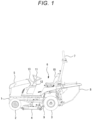
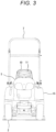
- a work vehicle such as a tractor includes: a right and left pair of front wheels 2 in a front portion under a machine body frame 1; a right and left pair of rear wheels 3 in a rear portion under the machine body frame 1; and a work machine 4 that is provided between the front wheels 2 and the rear wheels 3 under the machine body frame 1 to mowing a lawn or the like.
- the work vehicle further includes: a bonnet 5 that stores an engine E in a front portion above the machine body frame 1; an operation unit 6 that is provided behind the bonnet 5 and which a worker gets in; a safety frame 7 that is provided behind the control unit 6 to protect the worker; and a grass collection container 8 that is provided in a lower portion behind the safety frame 7 to store grass or the like mowed by the work machine 4.
- a shooter 9 communicates between a rear portion of the work machine 4 and a front portion of the grass collection container 8.
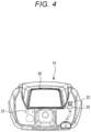
- a steering wheel 11 is provided in front of an operator's seat 10 in the operation unit 6, and the steering wheel 11 is supported by a steering column 12 via a steering shaft (not illustrated).
- a dashboard 13 is formed above the steering column 12.
- a cleaner lever 16 is provided on a fender 15 that is located on a left side of the operator's seat 10.
- a cleaner lever 16 drives a cleaner (not illustrated) that forcibly conveys the grass mowed by the work machine 4 to the grass collection container 8.
- a lift/lower lever 17 that lifts or lowers the work machine 4 is provided on a fender 15 that is located on a right side of the operator's seat 10.
- An accelerator pedal 19 that moves the work vehicle forward or in reverse is provided on a floor 18 that is located on the right side of the steering column 12.
- a meter panel 20 is provided to a central portion of the dashboard 13 and displays an output speed of the engine E and the like.
- a restriction cancellation switch (the "first switch” in the claims) 21 is provided on a rear left side of the meter panel 20.
- the restriction cancellation switch 21 cancels a restriction function that stops and restricts driving of the work machine 4 when the work vehicle travels in reverse.
- a restart switch 22 to restart the engine E and a start switch 23 to start the work machine 4 are provided on a rear right side of the meter panel 20.
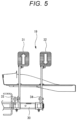
- the accelerator pedal 19 includes a forward accelerator pedal (the “first accelerator pedal” in the claims) 31 and a reverse accelerator pedal (the “second accelerator pedal” in the claims) 32, each of which is supported by a support shaft 30 extending in a right-left direction.
- the forward accelerator pedal moves the work vehicle forward
- the reverse accelerator pedal 32 moves the work vehicle in reverse.
- a rotary shaft 36 rotates in a clockwise direction via a forward arm 33 and a rotary body 35.
- the forward arm 33 is coupled to a base portion of the forward accelerator pedal 31, and the rotary body 35 is supported by the rotary shaft 36.
- the reverse accelerator pedal 32 is depressed, the rotary shaft 36 rotates in a counterclockwise direction via a reverse arm 34 and the rotary body 35.
- the reverse arm 34 is coupled to a base portion of the reverse accelerator pedal 32, and the rotary body 35 is supported by the rotary shaft 36.
- a rotation angle of the rotary shaft 36 is measured by an angle sensor 37 that is arranged near the rotary shaft 36.
- a neutral state In the neutral state, the work vehicle travels neither forward nor in reverse.
- output rotation of the engine E is transmitted to a continuously variable transmission 40.
- the output rotation the number of which is increased, reduced, or the like by the continuously variable transmission 40, is transmitted to the right and left pair of the rear wheels 3 via a differential gear 41 for rear wheels.
- a rotational speed of each of the rear wheels 3 is measured by a speed sensor 43.
- the output rotation of the continuously variable transmission 40 is also transmitted to the right and left pairs of the front wheels 2 via a differential gear 42 for front wheels when a drive switching device (not illustrated) is switched from two-wheel drive to four-wheel drive.
- the output rotation of the engine E is transmitted to a work clutch 46 via a speed increasing gear 45.
- the output rotation of the engine E is also transmitted to a right and left pair of mowing blades 48, which are installed in the work machine 4, via the work clutch 46 and a work rotary shaft 47.
- the mowing blades 48 can rotate to mow the lawn or the like.
- wind generated by the rotation of the mowing blades 48 efficiently conveys the residual mowed grass in the shooter 9 to the grass collection container 8.
- the work clutch 46 is disengaged, the output rotation of the engine E is not transmitted to the mowing blades 48 of the work machine 4, and the mowing blades 48 are stopped.
- the work clutch 46 When the start switch 23 is input, the work clutch 46 is engaged. When the input of the start switch 23 is cut off, the work clutch 46 is disengaged. When the work vehicle attempts to travel in reverse while the work clutch 46 is engaged, the work clutch 46 is disengaged. However, in the case where the restriction cancellation switch 21 is input, the work clutch 46 remains engaged even when the work vehicle travels in reverse.
- a controller 50 includes: a processing unit 51 including a CPU and the like; a storage unit 52 including ROM, RAM, a hard disk drive, flash memory, or the like; and a communication unit 53 for data communication with outside.
- the processing unit 51 calculates a travel speed of the work vehicle on the basis of a measured value by the speed sensor 43, and the like.
- the storage unit 52 stores a set speed, set time, and the like that are input on the meter panel 20.
- the communication unit 53 transmits information on the travel speed of the work vehicle and the like to an external portable controller.
- the restriction cancellation switch 21, the restart switch 22, the start switch (the "third switch” in the claims) 23, the angle sensor 37, and the speed sensor 43 are connected to an input side of the controller 50 via a predetermined input interface circuit.
- the restriction cancellation switch 21 cancels the restriction function that stops and restricts driving of the work machine 4 when the work vehicle travels in reverse.
- the restart switch 22 restarts the engine E, and the start switch 23 starts the work machine 4.
- the angle sensor 37 measures the rotation angle of the rotary shaft 36 that rotates by the depression of the forward accelerator pedal 31 or the reverse accelerator pedal 32.
- the speed sensor 43 measures the rotation speed of each of the rear wheels 3.
- the continuously variable transmission 40 and an alarm switch 63 are connected to an output side of the controller 50 via a predetermined output interface circuit.
- the continuously variable transmission 40 increases or reduces the number of the output rotation of the engine E.
- the alarm switch 63 is used by the work clutch 46, which is arranged in the transmission path between the engine E and the work machine 4, to sound an alarm.
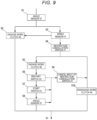
- step S1 in which the work clutch 46 is engaged and the mowing blades 48 of the work machine 4 rotate, the processing unit 51 of the controller 50 determines the measured value by the angle sensor 37 that measures the rotation angle of the rotary shaft 36. If it is determined that a current state is either a forward travel state where the forward accelerator pedal 31 is depressed and the work vehicle travels forward or the neutral state where neither the forward accelerator pedal 31 nor the reverse accelerator pedal 32 is depressed, the processing proceeds to step S2. If it is determined that the current state is a reverse travel state where the reverse accelerator pedal 32 is depressed and the work vehicle travels in reverse, the processing proceeds to step S3.
- step S2 the processing unit 51 maintains the engagement of the work clutch 46, and then the processing returns to step S1.
- step S3 the processing unit 51 determines the measured value by the speed sensor 43 that measures the rotational speed of each of the rear wheels 3. If the rotational speed of each of the rear wheels 3 is lower than or equal to the set speed that is input in advance on the meter panel 20, the processing returns to S2. If the rotational speed of each of the rear wheels 3 is higher than the set speed, the processing proceeds to step S4.
- step S4 the processing unit 51 determines an input state of the restriction cancellation switch 21, which cancels the restriction function of disengaging the work clutch 46 and restricting the engagement of the work clutch 46. If it is determined that the restriction cancellation switch 21 is input, the processing proceeds to step S5. If it is determined that the restriction cancellation switch 21 is not input, the processing proceeds to step S10.
- step S5 the processing unit 51 maintains the engagement of the work clutch 46, and then the processing proceeds to step S6.
- the mowing blades 48 of the work machine 4 can rotate to mow the lawn or the like, and thus mowing work efficiency can be improved.
- the wind generated by the rotation of the mowing blades 48 is blown into the shooter 9, which communicates between the rear portion of the work machine 4 and the front portion of the grass collection container 8. In this way, the residual mowed grass in the shooter 9 can be conveyed to the grass collection container 8.
- step S6 the processing unit 51 determines an input state of the restart switch 22, which stops the engine E once and then restarts the engine E. If it is determined that the restart switch 22 is not input, the processing proceeds to step S7. If it is determined that the restart switch 22 is input, the processing proceeds to step S9.
- step S7 the processing unit 51 determines an input state of the start switch 23, which engages or disengages the work clutch 46. If it is determined that the start switch 23 is input and the engagement of the work clutch 46 is maintained, the processing proceeds to step S8. If it is determined that the start switch 23 is not input and it is attempted to disengage the work clutch 46, the processing proceeds to step S9.
- step S8 the processing unit 51 determines the measured value by the angle sensor 37 that measures the rotation angle of rotary shaft 36. If it is determined that the current state is the reverse travel state where the reverse accelerator pedal 32 is depressed and the work vehicle travels in reverse, the processing returns to step S1. If it is determined that the current state is either the forward travel state where the forward accelerator pedal 31 is depressed and the work vehicle travels forward or the neutral state where neither the forward accelerator pedal 31 nor the reverse accelerator pedal 32 is depressed, the processing proceeds to step S9.
- step S9 the processing unit 51 cancels the input of the restriction cancellation switch 21, and the processing proceeds to step S10. In this way, it is possible to prevent the worker from forgetting to cut off the input of the restriction cancellation switch 21. Thus, it is possible to disengage the work clutch 46, stop the rotation of the mowing blades 48 of the work machine 4, and thereby improve the work safety when the engine E is restarted, when the work clutch 46 is disengaged, when the work vehicle travels forward, or the like.
- step S10 the processing unit 51 disengages the work clutch 46, and then the processing returns to step S1.
- the work clutch 46 is preferably disengaged after a predetermined time elapses. In this way, the wind generated by the rotation of the mowing blades 48 can convey the residual mowed grass in the shooter 9 to the grass collection container 8.
- the invention provides a work vehicle with a high mowing work efficiency that does not require a restart of an engine when an advancing direction of the work vehicle is switched from a reverse direction to a forward direction.
- the work vehicle includes a work machine (4) that mows grass, and stops rotation of a mowing blade (48) of the work machine (4) when the reverse travel of the work vehicle is detected.
- the work vehicle includes a first switch (21) that causes the mowing blade (48) of the work machine (4) to rotate when the work vehicle travels in reverse. In the case where the work vehicle is switched from the reverse travel to travel other than the reverse travel after an on-signal of the first switch (21) is input, input of an on-signal of the first switch (21) is canceled.
Landscapes
- Life Sciences & Earth Sciences (AREA)
- Environmental Sciences (AREA)
- Harvester Elements (AREA)
Applications Claiming Priority (1)
| Application Number | Priority Date | Filing Date | Title |
|---|---|---|---|
| JP2022149954A JP2024044444A (ja) | 2022-09-21 | 2022-09-21 | 作業車両 |
Publications (1)
| Publication Number | Publication Date |
|---|---|
| EP4342709A1 true EP4342709A1 (fr) | 2024-03-27 |
Family
ID=88097697
Family Applications (1)
| Application Number | Title | Priority Date | Filing Date |
|---|---|---|---|
| EP23198147.3A Pending EP4342709A1 (fr) | 2022-09-21 | 2023-09-19 | Véhicule de travail |
Country Status (2)
| Country | Link |
|---|---|
| EP (1) | EP4342709A1 (fr) |
| JP (1) | JP2024044444A (fr) |
Citations (5)
| Publication number | Priority date | Publication date | Assignee | Title |
|---|---|---|---|---|
| EP1541446A2 (fr) * | 2003-12-10 | 2005-06-15 | Deere & Company | Véhicule utilitaire |
| US20050274098A1 (en) * | 2004-06-01 | 2005-12-15 | Weber Steve J | Lawnmower override assembly apparatus and method |
| US20060201121A1 (en) * | 2005-03-09 | 2006-09-14 | Straka David A | Reverse operation safety circuit |
| EP3109091A1 (fr) * | 2007-09-11 | 2016-12-28 | Hydro-Gear Limited Partnership | Systèmes et procédés de commande pour véhicules utilitaires électriques |
| JP2020096558A (ja) | 2018-12-18 | 2020-06-25 | 井関農機株式会社 | 作業車両 |
-
2022
- 2022-09-21 JP JP2022149954A patent/JP2024044444A/ja active Pending
-
2023
- 2023-09-19 EP EP23198147.3A patent/EP4342709A1/fr active Pending
Patent Citations (5)
| Publication number | Priority date | Publication date | Assignee | Title |
|---|---|---|---|---|
| EP1541446A2 (fr) * | 2003-12-10 | 2005-06-15 | Deere & Company | Véhicule utilitaire |
| US20050274098A1 (en) * | 2004-06-01 | 2005-12-15 | Weber Steve J | Lawnmower override assembly apparatus and method |
| US20060201121A1 (en) * | 2005-03-09 | 2006-09-14 | Straka David A | Reverse operation safety circuit |
| EP3109091A1 (fr) * | 2007-09-11 | 2016-12-28 | Hydro-Gear Limited Partnership | Systèmes et procédés de commande pour véhicules utilitaires électriques |
| JP2020096558A (ja) | 2018-12-18 | 2020-06-25 | 井関農機株式会社 | 作業車両 |
Also Published As
| Publication number | Publication date |
|---|---|
| JP2024044444A (ja) | 2024-04-02 |
Similar Documents
| Publication | Publication Date | Title |
|---|---|---|
| US12268122B2 (en) | Work vehicle and grass mowing machine | |
| US10029571B2 (en) | Electric work vehicle | |
| EP3078252B1 (fr) | Véhicule de tonte | |
| US10967903B2 (en) | Electrically powered work vehicle | |
| US12201058B2 (en) | Riding grass mower with rotary blade drive selection unit | |
| EP1541446A2 (fr) | Véhicule utilitaire | |
| AU2021325092A1 (en) | Vehicle control module for autonomous vehicle | |
| EP2903849B1 (fr) | Système de commande de prise de force | |
| US20160355186A1 (en) | Electronic control systems for grounds maintenance vehicle | |
| US10816063B2 (en) | Work vehicle having implement | |
| US9038490B2 (en) | Tractors including automatic reset of a power takeoff circuit | |
| EP4663492A1 (fr) | Véhicule de travail | |
| JP2024044444A (ja) | 作業車両 | |
| JP7246086B2 (ja) | 自律制御型草刈機 | |
| EP4305944B1 (fr) | Système de commande pour véhicule de travail | |
| JPH1146550A (ja) | 自走式作物収穫機 | |
| US12550803B2 (en) | Work machine | |
| EP4151483B1 (fr) | Engin de chantier | |
| US20250065871A1 (en) | Work machine | |
| JP7503252B1 (ja) | コンバイン | |
| JP7797987B2 (ja) | 乗用芝刈機 | |
| US20250194458A1 (en) | Parameter Management System and Work Vehicle | |
| JP2025103509A (ja) | 作業車両 | |
| JPH04110233A (ja) | トラクターの前輪駆動制御装置 |
Legal Events
| Date | Code | Title | Description |
|---|---|---|---|
| PUAI | Public reference made under article 153(3) epc to a published international application that has entered the european phase |
Free format text: ORIGINAL CODE: 0009012 |
|
| STAA | Information on the status of an ep patent application or granted ep patent |
Free format text: STATUS: THE APPLICATION HAS BEEN PUBLISHED |
|
| AK | Designated contracting states |
Kind code of ref document: A1 Designated state(s): AL AT BE BG CH CY CZ DE DK EE ES FI FR GB GR HR HU IE IS IT LI LT LU LV MC ME MK MT NL NO PL PT RO RS SE SI SK SM TR |
|
| STAA | Information on the status of an ep patent application or granted ep patent |
Free format text: STATUS: REQUEST FOR EXAMINATION WAS MADE |
|
| 17P | Request for examination filed |
Effective date: 20240917 |
|
| RBV | Designated contracting states (corrected) |
Designated state(s): AL AT BE BG CH CY CZ DE DK EE ES FI FR GB GR HR HU IE IS IT LI LT LU LV MC ME MK MT NL NO PL PT RO RS SE SI SK SM TR |