EP4343061A2 - Machine à bourrer les ballasts de voie ferrée - Google Patents
Machine à bourrer les ballasts de voie ferrée Download PDFInfo
- Publication number
- EP4343061A2 EP4343061A2 EP24156261.0A EP24156261A EP4343061A2 EP 4343061 A2 EP4343061 A2 EP 4343061A2 EP 24156261 A EP24156261 A EP 24156261A EP 4343061 A2 EP4343061 A2 EP 4343061A2
- Authority
- EP
- European Patent Office
- Prior art keywords
- machine
- hand
- tamping machine
- handle
- vibration
- Prior art date
- Legal status (The legal status is an assumption and is not a legal conclusion. Google has not performed a legal analysis and makes no representation as to the accuracy of the status listed.)
- Withdrawn
Links
Images

Classifications
-
- E—FIXED CONSTRUCTIONS
- E01—CONSTRUCTION OF ROADS, RAILWAYS, OR BRIDGES
- E01B—PERMANENT WAY; PERMANENT-WAY TOOLS; MACHINES FOR MAKING RAILWAYS OF ALL KINDS
- E01B27/00—Placing, renewing, working, cleaning, or taking-up the ballast, with or without concurrent work on the track; Devices therefor; Packing sleepers
- E01B27/12—Packing sleepers, with or without concurrent work on the track; Compacting track-carrying ballast
- E01B27/13—Packing sleepers, with or without concurrent work on the track
- E01B27/14—Manual tools or hand-held power tools therefor
-
- E—FIXED CONSTRUCTIONS
- E01—CONSTRUCTION OF ROADS, RAILWAYS, OR BRIDGES
- E01B—PERMANENT WAY; PERMANENT-WAY TOOLS; MACHINES FOR MAKING RAILWAYS OF ALL KINDS
- E01B27/00—Placing, renewing, working, cleaning, or taking-up the ballast, with or without concurrent work on the track; Devices therefor; Packing sleepers
- E01B27/02—Placing the ballast; Making ballastway; Redistributing ballasting material; Machines or devices therefor; Levelling means
- E01B27/028—Compacting ballasting material; Performing ballast cores or seats for sleepers
-
- E—FIXED CONSTRUCTIONS
- E01—CONSTRUCTION OF ROADS, RAILWAYS, OR BRIDGES
- E01B—PERMANENT WAY; PERMANENT-WAY TOOLS; MACHINES FOR MAKING RAILWAYS OF ALL KINDS
- E01B27/00—Placing, renewing, working, cleaning, or taking-up the ballast, with or without concurrent work on the track; Devices therefor; Packing sleepers
- E01B27/12—Packing sleepers, with or without concurrent work on the track; Compacting track-carrying ballast
- E01B27/13—Packing sleepers, with or without concurrent work on the track
- E01B27/16—Sleeper-tamping machines
Definitions
- the invention relates to a hand tamping machine for compacting track ballast.
- a hand tamping machine for compacting track ballast is known from WO 2012/139 687 A1 .
- the hand tamping machine includes a tamping pick for penetrating the track ballast, a vibration generator, an internal combustion engine for rotating the vibration generator and handles for guiding the hand tamping machine during operation.
- Vibration dampers act between the vibration generator and the handles.
- the vibrations transmitted to the handles cannot be completely eliminated and are stressful for the user. Noise and exhaust emissions generated by the internal combustion engine place additional strain on the user.
- the invention is based on the object of improving a hand-held tamping machine for compacting track ballast, in particular to increase its ease of use and to reduce the stress it places on the user.
- a hand tamping machine has a particularly high level of operating comfort when along a shaft axis of a drive shaft, which connects the motor with the Vibration generator connects, at least one handle for guiding the hand tamping machine is arranged by at least 30% of the height of the hand tamping machine above the machine's center of gravity of the hand tamping machine and / or is arranged by at least 15% of the height of the hand tamping machine above the center of gravity of the motor.
- the arrangement of the at least one handle above the engine's center of gravity means that the user's head can be kept particularly far away from the engine that generates noise and / or pollutants. Due to its low-lying arrangement, the motor comes closer to the vibration generator. Surprisingly, however, it was found that the engine is not necessarily exposed to higher vibration loads as a result. Rather, by arranging it closer to the machine's center of gravity, a higher inertial damping can be achieved, which means that the vibrations transmitted to the motor can even be reduced.
- the lower center of gravity of the machine in relation to at least one handle makes it easier to control the hand tamping machine.
- the hand-held tamping machine that penetrates the track ballast is pivoted about a horizontal axis.
- a corresponding pivoting movement of the hand tamping machine from the vertical orientation is supported by a high center of gravity of the machine.
- the mass to be moved by the user and thus the total energy to be applied by the user, can be reduced due to the lower machine center of gravity, which means that the user tires less quickly.
- the longer lever arm offers better control over the hand tamping machine compared to the machine's center of gravity.
- a particular advantage of the hand tamping machine according to the invention is that the vibrations present on the at least one handle during operation and the associated stress on the user are particularly low. Due to the particularly low arrangement of the machine's center of gravity compared to the at least one handle, a vibration node of a rigid body vibration excited by the vibration generator can be relocated particularly close to the at least one handle. The resulting vibration amplitude on the at least one handle is therefore particularly low. Circulatory disorders and muscle diseases associated with continuous vibration stress can thus be prevented.
- the tamping pick points vertically downwards.
- Distances in relation to the at least one handle are, unless otherwise specified, to the top of the handle.
- the shaft axis is preferably arranged coaxially to the central longitudinal axis and/or to the vertical axis of the hand tamping machine.
- the machine center of gravity is understood to mean the center of gravity of the hand tamping machine, particularly when the hand tamping machine is in a ready-to-use state.
- a fuel tank of the engine is half full and a preferably replaceable ballast contact attachment is attached to the hand tamping machine.
- Guiding the hand tamping machine during operation means holding and moving the hand tamping machine when compacting the track ballast and/or carrying the hand tamping machine to the position of the track ballast to be processed.
- the handle device preferably has at least two, in particular exactly two or at least three, in particular at least four, of the handles.
- the position information provided in connection with the at least one handle preferably applies to all of the handles.
- the at least one handle can be formed by and/or attached to a support structure.
- the respective handle comprises a vibration-damping material, in particular a plastic and/or a rubber-elastic material.
- a power adjustment element, in particular a throttle lever, for regulating the power delivered by the engine can be arranged on the at least one handle, in particular in such a way that the user does not have to release his hand from the handle in order to operate the power adjustment element.
- the vibration generator is arranged at least in sections in a tamping pick tube. This allows the hand tamping machine to compact the track ballast in a particularly time- and energy-efficient manner.
- the vibration generator can have an unbalanced mass arranged eccentrically to the shaft axis, in particular completely within the tamping pick, in particular within a tamping pick tube. As a result, the vibration excitation can take place particularly close to the track ballast, whereby the kinetic energy used can be transferred to the track ballast largely without loss.
- the vibration excitation of the at least one handle and the motor is, however, reduced.
- the tamping pick preferably comprises an attachment support and a gravel contact attachment that can be detachably attached to the attachment support.
- the ballast contact attachment which is exposed to high stress due to contact with the track ballast, can therefore be easily replaced.
- the tamping pick in particular the attachment support, is preferably hollow, in particular tubular.
- the attachment support can be designed as a tamping pick tube.
- the vibration generator is arranged at least in sections within the tamping pick tube or tubular tamping pick.
- An unbalanced mass of the vibration generator can be arranged completely within the tamping pick tube and/or can be completely overlapped by the tamping pick tube along a direction perpendicular to the shaft axis.
- the vibration generator is preferably designed in such a way that the forces generated to stimulate the tamping pick to vibrate act perpendicular to the shaft axis, in particular in the horizontal direction.
- the transmission of vibrations oriented perpendicular to the shaft axis to the at least one handle and/or the motor is particularly strongly inhibited in the hand tamping machine according to the invention.
- the hand tamping machine preferably comprises the at least one handle, the motor center of gravity, the machine center of gravity and a tip of the tamping pick.
- a vibration node can thereby be arranged particularly close to the at least one handle along the shaft axis.
- the overall height of the hand tamping machine and/or the distance between the at least one handle and the underside of the Tamping picks in a range from 850 mm to 1250 mm, in particular from 950 mm to 1150 mm, in particular from 1000 mm to 1100 mm.
- a hand tamping machine is particularly user-friendly.
- the vibration movements transmitted to at least one handle are reduced even further.
- the hand tamping machine is even easier to operate.
- the machine center of gravity, in particular along the shaft axis of the drive shaft is preferably in a range from 30% to 70%, in particular from 35% to 65%, in particular from 40% to 60%, in particular from 45% to 55%, of the overall height the hand tamping machine is arranged below the at least one handle, in particular all of the handles.
- a hand tamping machine is particularly comfortable to use.
- the vibrations transmitted to the at least one handle are particularly low due to inertial damping by the machine mass.
- the at least one handle is preferably arranged at a maximum of 65%, in particular a maximum of 60%, in particular a maximum of 55%, in particular a maximum of 50%, in particular a maximum of 45%, of the height of the hand tamping machine above the machine's center of gravity.
- the at least one handle is preferably arranged at a maximum of 50%, in particular a maximum of 45%, in particular a maximum of 40%, in particular a maximum of 35%, in particular a maximum of 30%, in particular a maximum of 25%, above the engine's center of gravity of the engine. This makes it possible to achieve a particularly high level of operating comfort.
- a hand tamping machine is particularly user-friendly. By arranging the engine's center of gravity far away from the at least one handle, the user is less exposed to noise and/or exhaust emissions. Vibrations emanating from the motor are transmitted less strongly to the at least one handle due to the greater proximity to the machine's center of gravity and the resulting greater inertial damping.
- the motor center of gravity is preferably arranged along the shaft axis in a range from 15% to 50%, in particular from 20% to 40%, in particular from 25% to 30%, of the height of the hand tamping machine below the at least one, in particular all, handles.
- a hand tamping machine is particularly comfortable to use.
- the burden on the user caused by vibrations transmitted to the at least one handle is particularly low.
- the vibration node is preferably one, in particular the only, vibration node of a rigid body movement of the hand tamping machine caused by the vibration excitation of the vibration generator. Alternatively, this can be a vibration node due to an elastic deformation of the hand tamping machine and/or a natural vibration form of the hand tamping machine.
- the at least one handle is arranged along the shaft axis, preferably a maximum of 15%, in particular a maximum of 10%, in particular a maximum of 5%, of the overall height of the hand tamping machine from the oscillation node.
- the engine center of gravity along the shaft axis is a maximum of 15%, in particular a maximum of 10%, in particular a maximum of 5% of the height of the hand tamping machine is located away from a vibration node of the hand tamping machine due to the vibration excitation by the vibration generator. This allows the vibration loads transmitted to the engine to be reduced.
- a hand tamping machine is particularly comfortable to use.
- the burden on the user caused by vibrations transmitted to the at least one handle is particularly low.
- the vibration amplitude excited during operation of the hand tamping machine in the area of at least one handle is particularly low.
- the oscillation node is preferably detected in an operating state of the hand-held tamping machine in which no external forces act on the hand-held tamping machine and/or when the tamping pick has penetrated into the track ballast and/or when the tamping pick, in particular one, is fixed, in particular when fixed in position and/or orientation Tip of the darning pick.
- the first vibration decoupler preferably comprises a vibration damper.
- the first vibration decoupler can have at least one decoupling element, in particular an elastic element and/or a damping element, in particular a rubber-elastic body, in particular for connecting the handle device and/or the motor to the tamping pick and/or the vibration generator.
- the first vibration decoupler preferably acts between the handle device and/or motor and the tamping pick and/or the vibration generator and/or between the handle device and the motor.
- the first allows Vibration decoupler a limited relative movement between the handle device and / or the motor and the tamping pick and / or the vibration generator and / or between the handle device and the motor in a horizontal direction and / or in a vertical direction.
- the at least one handle and/or the motor can be decoupled from a vibration of the tamping pick and/or the vibration generator.
- a hand tamping machine is particularly comfortable to use. Due to the arrangement of the handle-side connection point and/or the tamping pick-side connection point of the first vibration decoupler above the center of gravity of the machine, this is particularly far away from the tamping pick, in particular the main vibration source of the hand-held tamping device.
- this connection point is arranged opposite the tamping pick in relation to the center of mass, whereby vibrations on the at least one handle are particularly comprehensively reduced by the particularly strong inertial damping in the area of the machine's center of gravity. The damping effect is increased and the vibration load on the user is reduced.
- a hand tamping machine ensures a particularly high level of operating comfort.
- the motor center of gravity and the handle-side connection point of the first vibration decoupler are preferably arranged along the shaft axis between the at least one handle and the machine center of gravity. This reduces the vibrations transmitted to the motor and/or the handle device.
- the vibrations excited on the at least one handle are particularly low if the ratio between the distance of the at least a handle from the motor center of gravity and the distance of the motor center of gravity from the handle-side connection point of the first vibration decoupler in a range from 1:1 to 4:1, in particular from 1.5:1 to 3.5:1, in particular from 2 :1 to 3:1. With this arrangement it is advantageously achieved that the mass of the motor exerts a particularly high intertial damping effect on the handle device.
- a hand tamping machine is particularly comfortable to use.
- the connection point of the first vibration decoupler on the tamping pick side can be arranged above or below the machine's center of gravity.
- the distance between the connection point on the tamping pick side of the first vibration decoupler and the machine's center of gravity is preferably a maximum of 15%, in particular a maximum of 10%, in particular a maximum of 5%, of the overall height of the hand tamping machine.
- the hand tamping machine experiences particularly high inertial damping in the area of the machine's center of gravity. A particularly strong reduction in the vibration transmitted to the handle device and/or the motor via the connection point on the tamping pick side of the first vibration decoupler can be achieved with such an arrangement.
- a hand tamping machine has a particularly high level of operating comfort during operation.
- the distance between the handle-side connection point of the first vibration decoupler and the machine center of gravity is a maximum of 20%, in particular a maximum of 15%, in particular a maximum of 10%, in particular a maximum of 5% of the overall height of the hand tamping machine.
- the handle-side connection point of the first vibration decoupler is along the shaft axis, preferably between the at least one handle and the machine's center of gravity and/or above the tamping pick-side Connection point of the first vibration decoupler arranged.
- the inertial damping due to the mass of the hand tamping machine has a particularly strong effect on reducing the vibrations on the at least one handle.
- a hand tamping machine is particularly easy to use. Because the first and/or the second vibration decoupler are arranged opposite the tamping pick and/or the vibration generator with respect to the machine's center of gravity, the vibrations transmitted thereto are reduced, in particular due to the particularly strong inertial damping in the area of the machine's center of gravity. Accordingly, the vibrations transmitted to the motor and/or the at least one handle are reduced.
- a hand tamping machine ensures even lower vibrations on the at least one handle.
- the hand tamping machine can have the first and/or the second vibration decoupler.
- the second vibration decoupler can be arranged above or below the first vibration decoupler or can overlap the first vibration decoupler along the shaft axis.
- the second vibration decoupler can be designed essentially in accordance with the first vibration decoupler.
- the second vibration decoupler is connected to the second vibration decoupler via a rigid head support structure, in particular a support plate.
- the second vibration decoupler preferably acts between the handle device and/or motor and the tamping pick and/or the vibration generator and/or between the handle device and the motor.
- the second vibration decoupler can provide a limited relative movement between the at least one handle and the tamping pick and/or the vibration generator and/or the motor and/or between the motor and the tamping pick and/or the vibration generator, in particular in any horizontal direction and/or in the vertical direction.
- the second vibration decoupler can have at least one decoupling element, in particular a spring element and/or a damping element, in particular a rubber-elastic element.
- the first and/or the second vibration decoupler preferably have several of the decoupling elements.
- a hand tamping machine can be used particularly flexibly.
- the hand tamping machine preferably comprises an energy source, in particular a fuel tank for supplying the internal combustion engine with fuel or an accumulator for supplying the electric motor with electrical power.
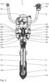
- a hand tamping machine 1 for compacting track ballast 2 is described.
- Track rails 3 are attached to track sleepers 4, which rest on the track ballast 2.
- the hand tamping machine 1 is shown in operation, with the hand tamping machine 1 penetrating the track ballast 2 in a vertical orientation to a depth below the track sleepers 4 for compacting the track ballast 2.
- the hand tamping machine 1 has a tamping pick 5, a vibration generator 6, a motor 7 and a handle device 8.
- the tamping pick 5 comprises a tamping pick tube 9 and a gravel contact attachment 10, which surrounds the tamping pick tube 9 at least in sections.
- the gravel contact attachment 10, which is subject to wear, is attached to the tamping pick tube 9 in an exchangeable manner.
- the vibration generator 6 is designed to stimulate the tamping pick 5 to vibrate.
- the motor 7 and the vibration generator 6 are designed to excite a vibration frequency in a range from 20 Hz to 100 Hz, in particular from 30 Hz to 60 Hz.
- the vibration generator 6 has an eccentric shaft 11, which is rotatably mounted in the tamping pick tube 9 about an eccentric axis 12 by means of two pipe bearings 13a, 13b.
- An unbalance mass 14 is attached to the eccentric shaft 11. In a direction perpendicular to the eccentric axis 12, the unbalanced mass 14 is completely overlapped by the tamping pick tube 9 and the ballast contact attachment 10.
- the engine 7 is an internal combustion engine, in particular a gasoline engine.
- the motor 7 can also be designed as an electric motor.
- the drive shaft 15 is rotatably mounted about a shaft axis 16.
- the drive shaft 15 is reversibly detachably connected to the eccentric shaft 11 and transmits torque.
- the drive shaft 15 can alternatively be non-detachably connected to the eccentric shaft 11, in particular formed in one piece with it.
- the eccentric shaft 11 and the drive shaft 15 are coaxial.
- the handle device 8 has two handles 17a, 17b.
- the handles 17a, 17b comprise a plastic, in particular they are designed as rubber handles.
- the engine 7 has a power adjustment element 18, in particular a throttle lever, for regulating the power output.
- the power adjustment element 18 is arranged on the first handle 17a in such a way that the user does not have to release his hand from the handle 17a to adjust the motor power.
- the handles 17a, 17b are connected to the motor 7 and the tamping pick 5 via a support structure 19.
- the support structure 19 is a tubular structure that essentially consists of metal.
- the hand tamping machine 1 has a first vibration decoupler 20 and a second vibration decoupler 21.
- the first vibration decoupler 20 acts between the tamping pick 5 and the handle device 8 and the motor 7.
- the first vibration decoupler 20 is connected to the tamping pick 5 via a connection point 22 on the tamping pick side.
- a handle-side connection point 23 of the first vibration decoupler 20 is connected to the handle device 8 and the motor 7.
- the first vibration decoupler 20 is attached to a pick support structure 24 via the connection point 22 on the tamping pick side.
- the first vibration decoupler 20 is attached to a head support structure 25 via the handle-side connection point 23.
- the head support structure 25 is designed as a support plate.
- the motor 7 is attached, in particular rigidly, to the head support structure 25.
- the second vibration decoupler 21 acts between the handle device 8 and the tamping pick 5 and the motor 7, in particular the head support structure 25.
- the second vibration decoupler 21 is connected to the tamping pick 5 via a connection point 26 on the tamping pick side, in particular attached to the head support structure 25.
- the second vibration decoupler 21 is connected to the handle device 8, in particular attached to the support structure 10, via a connection point 27 on the handle side.
- the first vibration decoupler 20 and the second vibration decoupler 21 each comprise four decoupling elements 28a, 28b made of a rubber-elastic material.
- the decoupling elements 28a, 28b of the respective vibration decoupler 20, 21 are connected in parallel with one another.
- the second vibration decoupler 21 is connected in series to the first vibration decoupler 20.
- the two vibration decouplers 20, 21 each enable a limited relative movement of the connection points 22, 26 on the tamping pick side to the connection points 23, 27 on the handle side in all spatial directions.
- the drive shaft is used to transmit power between the motor 5 and the vibration generator 6 while tolerating corresponding relative movements 15 designed in two parts.
- a third vibration decoupler 31 acts between a first drive shaft part 29 and a second drive shaft part 30.
- the first drive shaft part 29 is connected to the second drive shaft part 30 via the third vibration decoupler 31 in a torque-transmitting manner.
- the third vibration decoupler 31 enables a limited displacement of the first drive shaft part 29 to the second drive shaft part 30 along the shaft axis 16 and a limited relative pivoting movement about any axis perpendicular to the shaft axis 16.
- the hand tamping machine 1 has a height H of 1060 mm, which corresponds to the overall dimension of the hand tamping machine 1 along the shaft axis 16.
- a machine center of gravity SP0 is located along the shaft axis 16 in the middle of the hand tamping machine 1.
- the machine center of gravity SP0 is arranged from the handles 17a, 17b at a distance hG0 of 530 mm.
- a motor center of gravity SPM is arranged below the handles 17a, 17b at a distance hGM of 240 mm from the handles 17a, 17b. Accordingly, a distance h0M between the machine center of gravity SP0 and the motor center of gravity SPM is 290 mm.
- the handle-side connection point 23 of the first vibration decoupler 20 is arranged at a distance hT0 of 120 mm from the machine center of gravity SP0. Consequently, a distance hMT between the motor center of gravity SPM and the handle-side connection point 23 is 170 mm and the distance hGM between the motor center of gravity SPM and the handles 17a, 17b is 240 mm. A distance ht0 between the machine center of gravity SP0 and the tamping pick-side connection point 22 of the first vibration decoupler 20 is 60 mm.
- a distance h0F between the machine center of gravity SP0 and a force application point KP of the resulting eccentric force F provided by the vibration generator 6 is 383 mm.
- the functionality of the hand tamping machine 1 is as follows: The hand tamping machine 1 is in an operational state in which the fuel tank 32 is half full and the ballast contact attachment 10 is attached to the tamping pick tube 9.
- the user grasps the hand tamping machine 1 by the handles 17a, 17b in order to carry it to the location of the track ballast 2 to be compacted.
- the motor 7 is started and drives the vibration generator 6 according to the power set via the power setting element 18.
- the vibration generator 6 causes the tamping pick 5 to vibrate. Guided by the user via the handles 17a, 17b and under the influence of the weight of the hand tamping machine 1, the tamping pick 5 penetrates the track ballast 2.
- the tamping pick 5 transmits the vibration movement to the track ballast 2, which is thereby compacted.
- the user can pivot the hand tamping machine 1 about a horizontal axis, in particular oriented parallel to the respective track sleeper 4.
- compaction of the track ballast 2 below the track sleeper 4 can be achieved particularly efficiently and reliably.
- the vibrations excited on the handles 17a, 17b result at least in part from a rigid body movement of the hand tamping machine 1.
- the shaft axis 16 is shown in the vertical orientation of the hand tamping machine 1.
- the shaft axis 16 ' drawn obliquely to the vertical direction, symbolizes the rigid body movement of the track tamping machine 1 resulting from the eccentric force F.
- the resulting vibration amplitude is shown to be greatly exaggerated.
- the rigid body vibration does not take into account the limited rigidity of the hand tamping machine 1, in particular the vibration decoupler 20, 21.
- a vibration node SKP In a vibration node SKP, the position of which depends on the mass distribution of the hand tamping machine 1, there is a minimum of the oscillation amplitude, in particular this is zero.
- a distance hGP between the handles 17a, 17b and the oscillation node SKP is 60 mm. Due to the proximity of the handles 17a, 17b to the oscillation node SKP, the respective vibration amplitude present on the handles 17a, 17b is particularly low.
- the vibration decouplers 20, 21, 31 reduce the vibrations transmitted from the tamping pick 5 and/or the vibration generator 6 to the handle device 8, in particular the handles 17a, 17b, and the motor 7. This can shorten the service life of the motor 7 reduced stress can be extended. Furthermore, this results in considerable relief for the user.
- the large distance hGM between the handles 17a, 17b and the motor center of gravity SPM, especially in relation to the height H, has a particularly advantageous effect on the ease of use.
- the source of noise and/or exhaust emissions formed by the motor 7 is therefore particularly far away from the user's head.
- the motor 7 is arranged particularly close to the machine's center of gravity SP0, whereby the motor 7 is exposed to particularly low vibration loads due to the increased inertial damping there.
- the reaction forces acting on the user via the handles 17a, 17b depend on the aforementioned distances, in particular the arrangement of the machine center of gravity SP0, the motor center of gravity SPM, the force application point KP and the handle 17a, 17b along the Shaft axis 16.
- the present choice of distances results in particular in the arrangement of the handles 17a, 17b near the oscillation node SKP.
- the reaction forces acting on the user or the vibration excitation on the handles 17a, 17b are particularly low.
- the hand tamping machine 1 is therefore particularly user-friendly to operate.
Landscapes
- Engineering & Computer Science (AREA)
- Architecture (AREA)
- Civil Engineering (AREA)
- Structural Engineering (AREA)
- Road Paving Machines (AREA)
- Machines For Laying And Maintaining Railways (AREA)
- Investigation Of Foundation Soil And Reinforcement Of Foundation Soil By Compacting Or Drainage (AREA)
- Percussive Tools And Related Accessories (AREA)
Applications Claiming Priority (2)
| Application Number | Priority Date | Filing Date | Title |
|---|---|---|---|
| DE102021205469.2A DE102021205469A1 (de) | 2021-05-28 | 2021-05-28 | Handstopfmaschine zum Verdichten von Gleisschotter |
| EP22173664.8A EP4095313B1 (fr) | 2021-05-28 | 2022-05-17 | Machine portative à bourrer permettant de compacter des ballasts de voie ferrée |
Related Parent Applications (1)
| Application Number | Title | Priority Date | Filing Date |
|---|---|---|---|
| EP22173664.8A Division EP4095313B1 (fr) | 2021-05-28 | 2022-05-17 | Machine portative à bourrer permettant de compacter des ballasts de voie ferrée |
Publications (2)
| Publication Number | Publication Date |
|---|---|
| EP4343061A2 true EP4343061A2 (fr) | 2024-03-27 |
| EP4343061A3 EP4343061A3 (fr) | 2024-06-19 |
Family
ID=81850696
Family Applications (2)
| Application Number | Title | Priority Date | Filing Date |
|---|---|---|---|
| EP24156261.0A Withdrawn EP4343061A3 (fr) | 2021-05-28 | 2022-05-17 | Machine à bourrer les ballasts de voie ferrée |
| EP22173664.8A Active EP4095313B1 (fr) | 2021-05-28 | 2022-05-17 | Machine portative à bourrer permettant de compacter des ballasts de voie ferrée |
Family Applications After (1)
| Application Number | Title | Priority Date | Filing Date |
|---|---|---|---|
| EP22173664.8A Active EP4095313B1 (fr) | 2021-05-28 | 2022-05-17 | Machine portative à bourrer permettant de compacter des ballasts de voie ferrée |
Country Status (12)
| Country | Link |
|---|---|
| US (1) | US12486622B2 (fr) |
| EP (2) | EP4343061A3 (fr) |
| JP (1) | JP2022183132A (fr) |
| CN (1) | CN115404728A (fr) |
| AU (1) | AU2022203600A1 (fr) |
| BR (1) | BR102022009970A2 (fr) |
| CA (1) | CA3160841A1 (fr) |
| DE (1) | DE102021205469A1 (fr) |
| DK (1) | DK4095313T3 (fr) |
| ES (1) | ES2975163T3 (fr) |
| FI (1) | FI4095313T3 (fr) |
| PL (1) | PL4095313T3 (fr) |
Families Citing this family (2)
| Publication number | Priority date | Publication date | Assignee | Title |
|---|---|---|---|---|
| DE102021205469A1 (de) | 2021-05-28 | 2022-12-01 | Robel Bahnbaumaschinen Gmbh | Handstopfmaschine zum Verdichten von Gleisschotter |
| CN116516745A (zh) * | 2023-05-04 | 2023-08-01 | 安阳振动器有限责任公司 | 一种扭簧传动内燃便携式捣固机 |
Citations (2)
| Publication number | Priority date | Publication date | Assignee | Title |
|---|---|---|---|---|
| WO2012139687A1 (fr) | 2011-04-13 | 2012-10-18 | Robel Bahnbaumaschinen Gmbh | Bourroir manuel |
| DE102021205469A1 (de) | 2021-05-28 | 2022-12-01 | Robel Bahnbaumaschinen Gmbh | Handstopfmaschine zum Verdichten von Gleisschotter |
Family Cites Families (20)
| Publication number | Priority date | Publication date | Assignee | Title |
|---|---|---|---|---|
| US1341945A (en) * | 1919-12-23 | 1920-06-01 | Nathaniel C Study | Tamper and the like implement |
| US1431808A (en) * | 1922-02-23 | 1922-10-10 | Jackson Corwill | Tamper |
| DE2441180C3 (de) * | 1974-08-28 | 1981-06-11 | Koehring Gmbh - Bomag Division, 5407 Boppard | Von Hand geführter Vibrationsstampfer |
| SU610903A1 (ru) | 1975-12-25 | 1978-06-15 | Калужский Завод Транспортного Машиностроения | Электрическа шпалоподбойка |
| JPS5824562B2 (ja) * | 1977-12-16 | 1983-05-21 | 芝浦メカトロニクス株式会社 | タイタンパ |
| JPS5483210A (en) * | 1977-12-16 | 1979-07-03 | Shibaura Eng Works Ltd | Tie tamper |
| US4186197A (en) * | 1978-12-27 | 1980-01-29 | Susumu Tetsuo | Vibration ram |
| SU1051151A1 (ru) | 1982-07-05 | 1983-10-30 | Ленинградский Ордена Ленина Институт Инженеров Железнодорожного Транспорта Им.Акад.В.Н.Образцова | Электрическа шпалоподбойка |
| JPH10298913A (ja) * | 1997-04-25 | 1998-11-10 | Mikasa Sangyo Kk | タンピングランマー |
| JP2001003310A (ja) * | 1999-06-23 | 2001-01-09 | Sakai Heavy Ind Ltd | 締固め機 |
| JP2006029057A (ja) * | 2004-07-21 | 2006-02-02 | Ota Kensetsu Kk | タンピングランマー運搬移送時の支持金具 |
| JP4195045B2 (ja) * | 2006-05-31 | 2008-12-10 | 三笠産業株式会社 | ランマーの保護カバー構造 |
| CN201040818Y (zh) | 2006-09-25 | 2008-03-26 | 什邡瑞邦机械有限责任公司 | 手提式捣固镐 |
| JP2012241389A (ja) * | 2011-05-18 | 2012-12-10 | Hitachi Construction Machinery Camino Co Ltd | ランマ |
| JP2015031138A (ja) * | 2013-08-07 | 2015-02-16 | 株式会社日立建機カミーノ | ランマの転圧板 |
| CN203487421U (zh) | 2013-09-25 | 2014-03-19 | 南昌人和铁路科技设备有限公司 | 内燃捣固镐 |
| CN104264541B (zh) * | 2014-10-17 | 2016-11-02 | 安阳市安振高新产业有限责任公司 | 一种用于铁路道床捣固的便携式冲击镐 |
| DE202015001706U1 (de) * | 2015-03-05 | 2015-04-07 | Robel Bahnbaumschinen Gmbh | Handstopfer zum Unterstopfen von Schotter eines Gleises |
| EA202092780A1 (ru) | 2018-07-25 | 2021-03-01 | Робель Банбаумашинен Гмбх | Виброуплотнитель балластной подушки железнодорожного пути |
| CN211171454U (zh) | 2019-11-25 | 2020-08-04 | 北京安创工研科技有限公司 | 捣固器 |
-
2021
- 2021-05-28 DE DE102021205469.2A patent/DE102021205469A1/de not_active Ceased
-
2022
- 2022-05-17 EP EP24156261.0A patent/EP4343061A3/fr not_active Withdrawn
- 2022-05-17 DK DK22173664.8T patent/DK4095313T3/da active
- 2022-05-17 FI FIEP22173664.8T patent/FI4095313T3/fi active
- 2022-05-17 EP EP22173664.8A patent/EP4095313B1/fr active Active
- 2022-05-17 PL PL22173664.8T patent/PL4095313T3/pl unknown
- 2022-05-17 ES ES22173664T patent/ES2975163T3/es active Active
- 2022-05-23 BR BR102022009970-7A patent/BR102022009970A2/pt unknown
- 2022-05-25 US US17/824,251 patent/US12486622B2/en active Active
- 2022-05-26 CN CN202210585354.1A patent/CN115404728A/zh active Pending
- 2022-05-27 JP JP2022086864A patent/JP2022183132A/ja active Pending
- 2022-05-27 AU AU2022203600A patent/AU2022203600A1/en active Pending
- 2022-05-27 CA CA3160841A patent/CA3160841A1/fr active Pending
Patent Citations (2)
| Publication number | Priority date | Publication date | Assignee | Title |
|---|---|---|---|---|
| WO2012139687A1 (fr) | 2011-04-13 | 2012-10-18 | Robel Bahnbaumaschinen Gmbh | Bourroir manuel |
| DE102021205469A1 (de) | 2021-05-28 | 2022-12-01 | Robel Bahnbaumaschinen Gmbh | Handstopfmaschine zum Verdichten von Gleisschotter |
Also Published As
| Publication number | Publication date |
|---|---|
| US12486622B2 (en) | 2025-12-02 |
| EP4095313B1 (fr) | 2024-02-21 |
| PL4095313T3 (pl) | 2024-06-17 |
| JP2022183132A (ja) | 2022-12-08 |
| DK4095313T3 (da) | 2024-05-06 |
| AU2022203600A1 (en) | 2022-12-15 |
| CN115404728A (zh) | 2022-11-29 |
| ES2975163T3 (es) | 2024-07-03 |
| FI4095313T3 (fi) | 2024-05-15 |
| BR102022009970A2 (pt) | 2023-01-03 |
| CA3160841A1 (fr) | 2022-11-28 |
| EP4095313A1 (fr) | 2022-11-30 |
| EP4343061A3 (fr) | 2024-06-19 |
| DE102021205469A1 (de) | 2022-12-01 |
| US20220380986A1 (en) | 2022-12-01 |
Similar Documents
| Publication | Publication Date | Title |
|---|---|---|
| EP4095313B1 (fr) | Machine portative à bourrer permettant de compacter des ballasts de voie ferrée | |
| EP2434053B1 (fr) | Vibrocompacteur destiné à étanchéifier un sous-sol | |
| DE2216656C2 (de) | Erdbearbeitungsmaschine mit einem Erdbearbeitungswerkzeug | |
| DE2241692A1 (de) | Ruettelstampfer | |
| EP2980316A1 (fr) | Dispositif d'étanchéification de sol avec amortissement et guidage | |
| DE1634732A1 (de) | Gesteinsmeissel zum Ebnen oder Aufreissen von Felsboden | |
| DE102012006395A1 (de) | Handbediente Vibrationsvorrichtung mit vibrationsdämpfender Griffbefestigung | |
| DE112022002976T5 (de) | Plattenverdichter | |
| WO1998048119A1 (fr) | Compacteur destine au compactage du sol | |
| DE202009000264U1 (de) | Dämpfungselement | |
| AT523825B1 (de) | Maschine und Verfahren mit einem Stopfaggregat | |
| DE102019124415A1 (de) | Unwuchtsystem mit reduzierter rotationsträgheit für vibrationsverdichter | |
| EP1936037B1 (fr) | Compacteur de montage au vehicule | |
| DE102007003927B4 (de) | Schwingungsentlasteter Griff | |
| EP0267546B1 (fr) | Appareil vibratoire thérapeutique | |
| EP1012403B1 (fr) | Instrument de travail a vibrations massiques superieures reduites | |
| DE102016105950A1 (de) | Bodenverdichtungsvorrichtung mit entkoppeltem Führungshandgriff | |
| DE102014019139A1 (de) | Tiefenrüttler mit veränderbarer Unwucht | |
| DE102018128610A1 (de) | Vibrationsplatte mit geteilter Obermasse und schwingungsentkoppelter Führungseinrichtung | |
| EP3067470B1 (fr) | Vibrateur comme accessoire d'engin de chantier | |
| EP0945297A1 (fr) | Système d'échappement pour un véhicule automobile | |
| DE19739742A1 (de) | Arbeitsgerät mit Massenausgleich am Kurbeltrieb | |
| EP3237687B1 (fr) | Amortisseur de vibrations pour articulation d'accouplement d'un dispositif de vibration en profondeur | |
| DE102006041784A1 (de) | Schwingungserreger | |
| DE102020129941B3 (de) | Vorrichtung zum Lösen und Entfernen von verlegten Pflastersteinen aus einer Pflasterbettung sowie betreffende Arbeitsmaschinenanordnung |
Legal Events
| Date | Code | Title | Description |
|---|---|---|---|
| PUAI | Public reference made under article 153(3) epc to a published international application that has entered the european phase |
Free format text: ORIGINAL CODE: 0009012 |
|
| STAA | Information on the status of an ep patent application or granted ep patent |
Free format text: STATUS: THE APPLICATION HAS BEEN PUBLISHED |
|
| AC | Divisional application: reference to earlier application |
Ref document number: 4095313 Country of ref document: EP Kind code of ref document: P |
|
| AK | Designated contracting states |
Kind code of ref document: A2 Designated state(s): AL AT BE BG CH CY CZ DE DK EE ES FI FR GB GR HR HU IE IS IT LI LT LU LV MC MK MT NL NO PL PT RO RS SE SI SK SM TR |
|
| PUAL | Search report despatched |
Free format text: ORIGINAL CODE: 0009013 |
|
| AK | Designated contracting states |
Kind code of ref document: A3 Designated state(s): AL AT BE BG CH CY CZ DE DK EE ES FI FR GB GR HR HU IE IS IT LI LT LU LV MC MK MT NL NO PL PT RO RS SE SI SK SM TR |
|
| RIC1 | Information provided on ipc code assigned before grant |
Ipc: E01B 27/14 20060101AFI20240515BHEP |
|
| STAA | Information on the status of an ep patent application or granted ep patent |
Free format text: STATUS: THE APPLICATION IS DEEMED TO BE WITHDRAWN |
|
| 18D | Application deemed to be withdrawn |
Effective date: 20241220 |