EP4343200B1 - Dispositif d'éclairage ou dispositif d'éclairage pour un phare de véhicule automobile - Google Patents
Dispositif d'éclairage ou dispositif d'éclairage pour un phare de véhicule automobile Download PDFInfo
- Publication number
- EP4343200B1 EP4343200B1 EP22196548.6A EP22196548A EP4343200B1 EP 4343200 B1 EP4343200 B1 EP 4343200B1 EP 22196548 A EP22196548 A EP 22196548A EP 4343200 B1 EP4343200 B1 EP 4343200B1
- Authority
- EP
- European Patent Office
- Prior art keywords
- light
- light guide
- guide body
- total reflection
- reflection surface
- Prior art date
- Legal status (The legal status is an assumption and is not a legal conclusion. Google has not performed a legal analysis and makes no representation as to the accuracy of the status listed.)
- Active
Links
Images


Classifications
-
- F—MECHANICAL ENGINEERING; LIGHTING; HEATING; WEAPONS; BLASTING
- F21—LIGHTING
- F21S—NON-PORTABLE LIGHTING DEVICES; SYSTEMS THEREOF; VEHICLE LIGHTING DEVICES SPECIALLY ADAPTED FOR VEHICLE EXTERIORS
- F21S41/00—Illuminating devices specially adapted for vehicle exteriors, e.g. headlamps
- F21S41/20—Illuminating devices specially adapted for vehicle exteriors, e.g. headlamps characterised by refractors, transparent cover plates, light guides or filters
- F21S41/24—Light guides
-
- F—MECHANICAL ENGINEERING; LIGHTING; HEATING; WEAPONS; BLASTING
- F21—LIGHTING
- F21S—NON-PORTABLE LIGHTING DEVICES; SYSTEMS THEREOF; VEHICLE LIGHTING DEVICES SPECIALLY ADAPTED FOR VEHICLE EXTERIORS
- F21S41/00—Illuminating devices specially adapted for vehicle exteriors, e.g. headlamps
- F21S41/10—Illuminating devices specially adapted for vehicle exteriors, e.g. headlamps characterised by the light source
- F21S41/14—Illuminating devices specially adapted for vehicle exteriors, e.g. headlamps characterised by the light source characterised by the type of light source
- F21S41/141—Light emitting diodes [LED]
-
- F—MECHANICAL ENGINEERING; LIGHTING; HEATING; WEAPONS; BLASTING
- F21—LIGHTING
- F21S—NON-PORTABLE LIGHTING DEVICES; SYSTEMS THEREOF; VEHICLE LIGHTING DEVICES SPECIALLY ADAPTED FOR VEHICLE EXTERIORS
- F21S41/00—Illuminating devices specially adapted for vehicle exteriors, e.g. headlamps
- F21S41/10—Illuminating devices specially adapted for vehicle exteriors, e.g. headlamps characterised by the light source
- F21S41/14—Illuminating devices specially adapted for vehicle exteriors, e.g. headlamps characterised by the light source characterised by the type of light source
- F21S41/18—Combination of light sources of different types or shapes
-
- F—MECHANICAL ENGINEERING; LIGHTING; HEATING; WEAPONS; BLASTING
- F21—LIGHTING
- F21S—NON-PORTABLE LIGHTING DEVICES; SYSTEMS THEREOF; VEHICLE LIGHTING DEVICES SPECIALLY ADAPTED FOR VEHICLE EXTERIORS
- F21S41/00—Illuminating devices specially adapted for vehicle exteriors, e.g. headlamps
- F21S41/20—Illuminating devices specially adapted for vehicle exteriors, e.g. headlamps characterised by refractors, transparent cover plates, light guides or filters
- F21S41/285—Refractors, transparent cover plates, light guides or filters not provided in groups F21S41/24 - F21S41/2805
-
- F—MECHANICAL ENGINEERING; LIGHTING; HEATING; WEAPONS; BLASTING
- F21—LIGHTING
- F21S—NON-PORTABLE LIGHTING DEVICES; SYSTEMS THEREOF; VEHICLE LIGHTING DEVICES SPECIALLY ADAPTED FOR VEHICLE EXTERIORS
- F21S41/00—Illuminating devices specially adapted for vehicle exteriors, e.g. headlamps
- F21S41/30—Illuminating devices specially adapted for vehicle exteriors, e.g. headlamps characterised by reflectors
- F21S41/32—Optical layout thereof
-
- F—MECHANICAL ENGINEERING; LIGHTING; HEATING; WEAPONS; BLASTING
- F21—LIGHTING
- F21S—NON-PORTABLE LIGHTING DEVICES; SYSTEMS THEREOF; VEHICLE LIGHTING DEVICES SPECIALLY ADAPTED FOR VEHICLE EXTERIORS
- F21S43/00—Signalling devices specially adapted for vehicle exteriors, e.g. brake lamps, direction indicator lights or reversing lights
- F21S43/10—Signalling devices specially adapted for vehicle exteriors, e.g. brake lamps, direction indicator lights or reversing lights characterised by the light source
- F21S43/13—Signalling devices specially adapted for vehicle exteriors, e.g. brake lamps, direction indicator lights or reversing lights characterised by the light source characterised by the type of light source
- F21S43/14—Light emitting diodes [LED]
-
- F—MECHANICAL ENGINEERING; LIGHTING; HEATING; WEAPONS; BLASTING
- F21—LIGHTING
- F21S—NON-PORTABLE LIGHTING DEVICES; SYSTEMS THEREOF; VEHICLE LIGHTING DEVICES SPECIALLY ADAPTED FOR VEHICLE EXTERIORS
- F21S43/00—Signalling devices specially adapted for vehicle exteriors, e.g. brake lamps, direction indicator lights or reversing lights
- F21S43/10—Signalling devices specially adapted for vehicle exteriors, e.g. brake lamps, direction indicator lights or reversing lights characterised by the light source
- F21S43/13—Signalling devices specially adapted for vehicle exteriors, e.g. brake lamps, direction indicator lights or reversing lights characterised by the light source characterised by the type of light source
- F21S43/15—Strips of light sources
-
- F—MECHANICAL ENGINEERING; LIGHTING; HEATING; WEAPONS; BLASTING
- F21—LIGHTING
- F21S—NON-PORTABLE LIGHTING DEVICES; SYSTEMS THEREOF; VEHICLE LIGHTING DEVICES SPECIALLY ADAPTED FOR VEHICLE EXTERIORS
- F21S43/00—Signalling devices specially adapted for vehicle exteriors, e.g. brake lamps, direction indicator lights or reversing lights
- F21S43/20—Signalling devices specially adapted for vehicle exteriors, e.g. brake lamps, direction indicator lights or reversing lights characterised by refractors, transparent cover plates, light guides or filters
- F21S43/235—Light guides
- F21S43/236—Light guides characterised by the shape of the light guide
- F21S43/239—Light guides characterised by the shape of the light guide plate-shaped
-
- F—MECHANICAL ENGINEERING; LIGHTING; HEATING; WEAPONS; BLASTING
- F21—LIGHTING
- F21S—NON-PORTABLE LIGHTING DEVICES; SYSTEMS THEREOF; VEHICLE LIGHTING DEVICES SPECIALLY ADAPTED FOR VEHICLE EXTERIORS
- F21S43/00—Signalling devices specially adapted for vehicle exteriors, e.g. brake lamps, direction indicator lights or reversing lights
- F21S43/20—Signalling devices specially adapted for vehicle exteriors, e.g. brake lamps, direction indicator lights or reversing lights characterised by refractors, transparent cover plates, light guides or filters
- F21S43/235—Light guides
- F21S43/236—Light guides characterised by the shape of the light guide
- F21S43/241—Light guides characterised by the shape of the light guide of complex shape
-
- F—MECHANICAL ENGINEERING; LIGHTING; HEATING; WEAPONS; BLASTING
- F21—LIGHTING
- F21S—NON-PORTABLE LIGHTING DEVICES; SYSTEMS THEREOF; VEHICLE LIGHTING DEVICES SPECIALLY ADAPTED FOR VEHICLE EXTERIORS
- F21S43/00—Signalling devices specially adapted for vehicle exteriors, e.g. brake lamps, direction indicator lights or reversing lights
- F21S43/20—Signalling devices specially adapted for vehicle exteriors, e.g. brake lamps, direction indicator lights or reversing lights characterised by refractors, transparent cover plates, light guides or filters
- F21S43/235—Light guides
- F21S43/242—Light guides characterised by the emission area
- F21S43/245—Light guides characterised by the emission area emitting light from one or more of its major surfaces
-
- F—MECHANICAL ENGINEERING; LIGHTING; HEATING; WEAPONS; BLASTING
- F21—LIGHTING
- F21S—NON-PORTABLE LIGHTING DEVICES; SYSTEMS THEREOF; VEHICLE LIGHTING DEVICES SPECIALLY ADAPTED FOR VEHICLE EXTERIORS
- F21S43/00—Signalling devices specially adapted for vehicle exteriors, e.g. brake lamps, direction indicator lights or reversing lights
- F21S43/20—Signalling devices specially adapted for vehicle exteriors, e.g. brake lamps, direction indicator lights or reversing lights characterised by refractors, transparent cover plates, light guides or filters
- F21S43/235—Light guides
- F21S43/247—Light guides with a single light source being coupled into the light guide
-
- F—MECHANICAL ENGINEERING; LIGHTING; HEATING; WEAPONS; BLASTING
- F21—LIGHTING
- F21S—NON-PORTABLE LIGHTING DEVICES; SYSTEMS THEREOF; VEHICLE LIGHTING DEVICES SPECIALLY ADAPTED FOR VEHICLE EXTERIORS
- F21S43/00—Signalling devices specially adapted for vehicle exteriors, e.g. brake lamps, direction indicator lights or reversing lights
- F21S43/20—Signalling devices specially adapted for vehicle exteriors, e.g. brake lamps, direction indicator lights or reversing lights characterised by refractors, transparent cover plates, light guides or filters
- F21S43/235—Light guides
- F21S43/249—Light guides with two or more light sources being coupled into the light guide
-
- F—MECHANICAL ENGINEERING; LIGHTING; HEATING; WEAPONS; BLASTING
- F21—LIGHTING
- F21S—NON-PORTABLE LIGHTING DEVICES; SYSTEMS THEREOF; VEHICLE LIGHTING DEVICES SPECIALLY ADAPTED FOR VEHICLE EXTERIORS
- F21S43/00—Signalling devices specially adapted for vehicle exteriors, e.g. brake lamps, direction indicator lights or reversing lights
- F21S43/20—Signalling devices specially adapted for vehicle exteriors, e.g. brake lamps, direction indicator lights or reversing lights characterised by refractors, transparent cover plates, light guides or filters
- F21S43/26—Refractors, transparent cover plates, light guides or filters not provided in groups F21S43/235 - F21S43/255
-
- F—MECHANICAL ENGINEERING; LIGHTING; HEATING; WEAPONS; BLASTING
- F21—LIGHTING
- F21S—NON-PORTABLE LIGHTING DEVICES; SYSTEMS THEREOF; VEHICLE LIGHTING DEVICES SPECIALLY ADAPTED FOR VEHICLE EXTERIORS
- F21S43/00—Signalling devices specially adapted for vehicle exteriors, e.g. brake lamps, direction indicator lights or reversing lights
- F21S43/30—Signalling devices specially adapted for vehicle exteriors, e.g. brake lamps, direction indicator lights or reversing lights characterised by reflectors
- F21S43/31—Optical layout thereof
- F21S43/315—Optical layout thereof using total internal reflection
-
- F—MECHANICAL ENGINEERING; LIGHTING; HEATING; WEAPONS; BLASTING
- F21—LIGHTING
- F21V—FUNCTIONAL FEATURES OR DETAILS OF LIGHTING DEVICES OR SYSTEMS THEREOF; STRUCTURAL COMBINATIONS OF LIGHTING DEVICES WITH OTHER ARTICLES, NOT OTHERWISE PROVIDED FOR
- F21V7/00—Reflectors for light sources
- F21V7/04—Optical design
- F21V7/041—Optical design with conical or pyramidal surface
-
- F—MECHANICAL ENGINEERING; LIGHTING; HEATING; WEAPONS; BLASTING
- F21—LIGHTING
- F21W—INDEXING SCHEME ASSOCIATED WITH SUBCLASSES F21K, F21L, F21S and F21V, RELATING TO USES OR APPLICATIONS OF LIGHTING DEVICES OR SYSTEMS
- F21W2103/00—Exterior vehicle lighting devices for signalling purposes
- F21W2103/20—Direction indicator lights
-
- F—MECHANICAL ENGINEERING; LIGHTING; HEATING; WEAPONS; BLASTING
- F21—LIGHTING
- F21W—INDEXING SCHEME ASSOCIATED WITH SUBCLASSES F21K, F21L, F21S and F21V, RELATING TO USES OR APPLICATIONS OF LIGHTING DEVICES OR SYSTEMS
- F21W2103/00—Exterior vehicle lighting devices for signalling purposes
- F21W2103/55—Daytime running lights [DRL]
-
- F—MECHANICAL ENGINEERING; LIGHTING; HEATING; WEAPONS; BLASTING
- F21—LIGHTING
- F21Y—INDEXING SCHEME ASSOCIATED WITH SUBCLASSES F21K, F21L, F21S and F21V, RELATING TO THE FORM OR THE KIND OF THE LIGHT SOURCES OR OF THE COLOUR OF THE LIGHT EMITTED
- F21Y2115/00—Light-generating elements of semiconductor light sources
- F21Y2115/10—Light-emitting diodes [LED]
Definitions
- the individual structures are distributed uniformly and/or in rows and/or columns over the total reflection surface.
- the two light exit surfaces can be inclined at an angle greater than 90° to each other, resulting in a V-shaped arrangement of the two light exit surfaces to each other.
- the upper light exit surface is located approximately at the same height as the one or more light sources, and/or wherein preferably the total reflection surface is located approximately at the same height as the at least one light source.
- the total reflection surface runs transversely to the main propagation direction of the optical fiber and is preferably inclined such that an upper edge region is closer to the at least one light source than a lower edge region.
- each facet represents a substantially rectangular, flat surface.
- the normal vector to this surface can be decomposed into a horizontal component lying in a substantially horizontal plane containing the optical fiber main propagation direction X, and a vertical component lying in a vertical plane normal to the plane parallel to the substantially horizontal plane.
- all facets are rotated by the same angle with respect to the main optical fiber propagation direction.
- tilt angle is the angle that the horizontal component of the normal vector makes to the main propagation direction of the optical fiber.
- the facets lie next to each other in one or more rows one above the other.
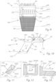
- the recesses 202 are pyramid-shaped, with a triangular opening 2021 and base surface 2022 and the two further lateral surfaces 2023, 2024 extending into the light guide body 100.
- Triangular does not necessarily mean that the connecting lines between two vertices of the "triangle” must be straight (in this respect, it is a “modified” triangle).
- pyramidal means that the shape of the depression is similar but not necessarily identical to a pyramid, for example, by having curved, not flat, surfaces.
- the two further lateral surfaces 2023, 2024 are preferably flat and are aligned substantially parallel to or in the direction of the light rays incident on the individual structure 202, i.e. preferably parallel to the main propagation direction X of the optical fiber.
- the base surface 2022 is curved, in particular into the light guide body 100.
- a surface normal to the base surface 2022 thus runs essentially parallel to the main light guide propagation direction X, wherein, for example, it is provided that the surface normal runs through the geometric center of the lateral surface and, in particular, runs normal to a tangential surface to the base surface at this center.
- This curvature can (see Figure 7 ) a splitting/expanding effect on an incident light beam of parallel light rays S1 can be achieved, so that the light rays are evenly distributed over the light exit surface 161 and this shines evenly brightly.
- the depressions 202 are cylindrical in shape, at least in sections.
- This design of the depressions 202 is advantageous here, since in this variant the distinguished straight line g50 and the straight line g161 (see the explanations for the variant according to Figure 1 ) run parallel to each other ( Figure 9 ) and transverse and normal to the main fiber propagation direction X. In this example, the lines g161, g162, g201 also run parallel to the marked line g50.
- the recesses each represent a "cutout" in the light guide or in the total reflection surface, starting from the total reflection surface 201, with a lateral surface 2022 of the recess being formed in the form of a portion of a cylindrical surface. This lateral surface, or the height of the cylindrical surface, runs essentially vertically.
- the incident light rays S1 are directed to the first light exit surface 161 via this lateral surface 2022.
- the lateral surface is curved, in particular curved into the light guide body 100, so that, as in the embodiment according to Figure 1 the light rays S1 are "scattered” accordingly (splitting/expanding effect on an incident light beam of parallel light rays S1), so that the light exit surface 161 is subsequently illuminated more evenly.
- the recess 202 is bounded by three further, preferably flat lateral surfaces 2023, 2024a, 2024b, which "open" into the opening of the recess.
- these surfaces are two lateral lateral surfaces 2024a, 2024b and a bottom lateral surface 2023, which are preferably flat.
- These flat lateral surfaces 2023, 2024a, 2024b preferably extend parallel to the main radiation direction X.
- the opening surfaces lie in the plane of the total reflection surface.
- the total reflection surface can be faceted, i.e., divided into several, preferably flat, facets.
- the opening surfaces lie in the plane of the respective facet, from which the recess extends into the light guide body.
- the area A total can be calculated by the sum of the areas of the facets 201A, from which areas the depressions 202 extend into the light guide body 100.
- the design according to the invention ensures that the light emitted by the light source(s) is divided according to the ratio of the size of the two light exit surfaces, so that both light exit surfaces are irradiated with the same light intensity and thus have the same luminance or surface brightness.
Landscapes
- Engineering & Computer Science (AREA)
- General Engineering & Computer Science (AREA)
- Physics & Mathematics (AREA)
- Microelectronics & Electronic Packaging (AREA)
- Optics & Photonics (AREA)
- Non-Portable Lighting Devices Or Systems Thereof (AREA)
- Planar Illumination Modules (AREA)
- Light Guides In General And Applications Therefor (AREA)
Claims (15)
- Dispositif de signalisation ou d'illumination (10) pour un véhicule automobile ou pour un projecteur de véhicule automobile, comprenant :- au moins une source lumineuse (50) pour l'émission de rayons lumineux,- un corps de guidage de lumière (100) associé à la au moins une source de lumière (50),le corps de guidage de lumière (100) comprenant une section d'injection (110) ainsi qu'une zone de sortie de lumière (160),des rayons lumineux, qui sont émis par la au moins une source de lumière (50), étant émis par la section d'injection (110), sont couplés dans le corps de guidage de la lumière (100), se propagent dans le corps de guidage de la lumière (100) et sortent du corps de guidage de la lumière (100) par la zone de sortie de la lumière (160),la zone de sortie de la lumière (160) comprenant deux surfaces de sortie de la lumière (161, 162), dans lequel la section de couplage (110) est formée, par exemple sous la forme d'un collimateur (111), de telle sorte que les rayons lumineux émis par ladite au moins une source de lumière (50) sont orientés sensiblement dans une direction principale de propagation de guide de lumière (X),caractérisé en ce que le corps de guide de lumière (100) comprend un dispositif de division de faisceau (200),dans lequelle dispositif de division de faisceau (200) comprend une surface de réflexion totale (201) qui réfléchit totalement au moins une partie des rayons lumineux (S1) qui la frappent, de sorte que ces rayons lumineux (S3) se propagent dans le corps de guide de lumière (100) dans une direction (Z) différente de la direction principale de propagation du guide de lumière (X),et dans lequel la surface de réflexion totale (201) présente des structures optiques individuelles (202), qui sont conçues de telle sorte qu'au moins une partie des rayons lumineux (S1) incidents sur une structure individuelle (202) sortent du corps de guidage de lumière (100) par la structure individuelle (202), pénètrent à nouveau dans le corps de guidage de lumière (100) par une surface de rentrée (203), les rayons lumineux (S2) rentrés étant dirigés vers l'une des surfaces de sortie de lumière, de la « première » surface de sortie de lumière (161), laquelle première surface de sortie de lumière (161) est opposée à la surface de rentrée (203), de sorte que ces rayons lumineux peuvent sortir de la première surface de sortie de lumière (161) dans une direction de rayonnement principale (Y),et dans lequel les rayons lumineux (S3) totalement réfléchis par la surface de réflexion totale (201) sont totalement réfléchis sur une face arrière (101) du corps de guidage de lumière (100) et sont ainsi déviés vers la deuxième surface de sortie de lumière (162), où les rayons lumineux (S5) sortent du corps de guidage de lumière (100) dans la direction de la direction de rayonnement principale (Y),dans lequel chaque structure optique individuelle (202) est formée comme un creux dans la surface de réflexion totale (201),un creux, partant d'une ouverture (2021) dans le corps de guidage de lumière (100), étant délimité par des surfaces d'enveloppe (2022, 2023, 2024 ; 2022, 2023, 2024a, 2024b),l'une des surfaces d'enveloppe, dite surface de base (2022), étant orientée de telle sorte que les rayons lumineux (S1) qui la frappent traversent la surface de base (2022) en direction de la première surface de sortie de lumière (161), etchaque ouverture (2021) laissant une surface, dite surface d'ouverture, dans la surface de réflexion totale (201), une surface d'ouverture ayant une aire d'ouverture AB,i, la surface de réflexion totale (201) ayant une aire totale Ages, Ages comprenant la somme de toutes les aires d'ouverture, et la première surface de sortie de lumière (161) ayant une première aire A1 et la deuxième surface de sortie de lumière (162) ayant une deuxième aire A2, et où

- Dispositif selon la revendication 1, dans lequel les autres surfaces d'enveloppe (2023, 2024 ; 2023, 2024a, 2024b) sont orientées sensiblement parallèlement aux rayons lumineux incidents sur la structure individuelle (202) ou en direction de ces rayons.
- Dispositif selon la revendication 1 ou 2, dans lequel les cavités (202) sont de forme pyramidale, avec une ouverture triangulaire (2021), une surface de base (2022) et deux surfaces d'enveloppe (2023, 2024) s'étendant dans le corps de guidage de lumière (100).
- Dispositif selon la revendication 1 ou 2, dans lequel les cavités (202) sont de forme cylindrique au moins par sections.
- Dispositif selon l'une des revendications 1 à 4, dans lequel la surface de base (2022) est incurvée, notamment dans le corps de guide de lumière (100), les autres surfaces d'enveloppe (2023, 2024 ; 2023, 2024a, 2024b) étant de préférence planes, les surfaces d'enveloppe planes (2023, 2024) s'étendant par exemple parallèlement à la direction principale de propagation (X) du guide de lumière.
- Dispositif selon l'une quelconque des revendications précédentes, dans lequel les structures individuelles (202) sont réparties uniformément et/ou en lignes et/ou en colonnes sur la surface de réflexion totale (201).
- Dispositif selon l'une des revendications précédentes, dans lequel il est prévu deux ou plusieurs sources lumineuses (50), dans lequel, pour respectivement une ou plusieurs des sources lumineuses (50), la section de couplage (110) est réalisée de telle manière, par ex. sous la forme d'un collimateur (111), de sorte que les rayons lumineux émis par chaque source de lumière (50) sont orientés essentiellement dans la direction principale de propagation (X) du guide de lumière, les sources de lumière (50) étant de préférence disposées en une rangée, en particulier latéralement les unes à côté des autres et transversalement à la direction principale de propagation (X) du guide de lumière.
- Dispositif selon l'une des revendications précédentes, dans lequel les surfaces de sortie de lumière (161, 162) sont directement adjacentes l'une à l'autre, notamment se rejoignent en un bord droit, et/ou une surface de sortie de lumière (161) est disposée au-dessus de l'autre surface de sortie de lumière (162).
- Dispositif selon l'une des revendications 1 à 8, dans lequel, lors d'une intersection des surfaces de sortie de lumière (161, 162) avec une surface horizontale, les droites d'intersection (g161, g162) obtenues en supposant que les surfaces de sortie de lumière (161, 162) sont planes,- soit parallèles à une droite excellente (g50), soit- s'étendent obliquement par rapport à la droite excellente (g50),la droite excellente (g50) étant une droite qui se trouve dans un plan horizontal et qui s'étend perpendiculairement à la direction principale de propagation de la fibre optique (X).
- Dispositif selon la revendication 9, dans lequel une droite d'intersection (g201), qui est obtenue lors d'une coupe horizontale à travers la surface de réflexion totale (201), est soit- parallèle à la droite marquée (g50), soit- oblique par rapport à la ligne droite excellente (g50).
- Dispositif selon l'une quelconque des revendications précédentes, dans lequel la première surface de sortie de lumière (161) est située sensiblement à la même hauteur que la ou les sources de lumière (50), et/ou dans lequel, de préférence, la surface de réflexion totale (201) est située sensiblement à la même hauteur que la ou les sources de lumière (50).
- Dispositif selon l'une des revendications précédentes, dans lequel la surface de réflexion totale (201) est divisée en plusieurs facettes (201A), des facettes (201A) étant situées latéralement les unes à côté des autres, et dans lequel, de préférence, les facettes sont chacune tordues selon un angle supérieur à 0° et inférieur à 90° par rapport à la direction principale de propagation (X) du guide de lumière.
- Dispositif selon l'une des revendications précédentes, dans lequel l'au moins une source lumineuse (50) est conçue comme une LED ou comprend au moins une LED.
- Projecteur de véhicule automobile comprenant un ou plusieurs dispositifs selon l'une quelconque des revendications 1 à 13.
- Véhicule automobile comprenant un ou plusieurs dispositifs selon l'une quelconque des revendications 1 à 13 et/ou un ou plusieurs projecteurs de véhicule automobile selon la revendication 14.
Priority Applications (5)
| Application Number | Priority Date | Filing Date | Title |
|---|---|---|---|
| EP22196548.6A EP4343200B1 (fr) | 2022-09-20 | 2022-09-20 | Dispositif d'éclairage ou dispositif d'éclairage pour un phare de véhicule automobile |
| JP2023143855A JP7628161B2 (ja) | 2022-09-20 | 2023-09-05 | 自動車投光器用の信号灯装置又は照射装置 |
| KR1020230120920A KR102942220B1 (ko) | 2022-09-20 | 2023-09-12 | 자동차 헤드라이트용 신호 발광 장치 또는 조명 장치 |
| US18/369,495 US11971151B2 (en) | 2022-09-20 | 2023-09-18 | Signal lighting device or lighting device for motor vehicle headlamp |
| CN202311208855.9A CN117739299A (zh) | 2022-09-20 | 2023-09-19 | 信号灯装置或照明装置、机动车辆前照灯及机动车辆 |
Applications Claiming Priority (1)
| Application Number | Priority Date | Filing Date | Title |
|---|---|---|---|
| EP22196548.6A EP4343200B1 (fr) | 2022-09-20 | 2022-09-20 | Dispositif d'éclairage ou dispositif d'éclairage pour un phare de véhicule automobile |
Publications (2)
| Publication Number | Publication Date |
|---|---|
| EP4343200A1 EP4343200A1 (fr) | 2024-03-27 |
| EP4343200B1 true EP4343200B1 (fr) | 2025-07-02 |
Family
ID=83398413
Family Applications (1)
| Application Number | Title | Priority Date | Filing Date |
|---|---|---|---|
| EP22196548.6A Active EP4343200B1 (fr) | 2022-09-20 | 2022-09-20 | Dispositif d'éclairage ou dispositif d'éclairage pour un phare de véhicule automobile |
Country Status (5)
| Country | Link |
|---|---|
| US (1) | US11971151B2 (fr) |
| EP (1) | EP4343200B1 (fr) |
| JP (1) | JP7628161B2 (fr) |
| KR (1) | KR102942220B1 (fr) |
| CN (1) | CN117739299A (fr) |
Families Citing this family (4)
| Publication number | Priority date | Publication date | Assignee | Title |
|---|---|---|---|---|
| EP4166843B1 (fr) * | 2021-10-18 | 2024-04-03 | Volkswagen Ag | Dispositif d'éclairage pour un véhicule automobile |
| EP4494940A1 (fr) * | 2023-07-21 | 2025-01-22 | ZKW Group GmbH | Dispositif d'éclairage pour un feu de véhicule automobile |
| EP4538590A1 (fr) * | 2023-10-09 | 2025-04-16 | ZKW Group GmbH | Dispositif d'éclairage ou d'éclairage de signal pour un vehicule |
| EP4650654A1 (fr) * | 2024-05-16 | 2025-11-19 | Hella Autotechnik Nova s.r.o. | Guide de lumière coudé pour lampe de véhicule et lampe de véhicule avec le guide de lumière |
Family Cites Families (13)
| Publication number | Priority date | Publication date | Assignee | Title |
|---|---|---|---|---|
| FR2952163B1 (fr) * | 2009-11-02 | 2013-08-23 | Valeo Vision | Dispositif d'eclairage ou de signalisation pour vehicule automobile comprenant un guide de lumiere |
| EP2354637B1 (fr) * | 2010-01-30 | 2020-03-04 | HELLA GmbH & Co. KGaA | Dispositif d'éclairage pour véhicules |
| JP5814302B2 (ja) * | 2013-06-18 | 2015-11-17 | 株式会社小糸製作所 | 車輌用灯具 |
| FR3042751B1 (fr) * | 2015-10-23 | 2018-09-07 | Automotive Lighting Rear Lamps France | Dispositif d'eclairage et/ou de signalisation compact pour vehicule |
| AT518552B1 (de) | 2016-08-19 | 2017-11-15 | Zkw Group Gmbh | Beleuchtungseinheit für einen Kraftfahrzeugscheinwerfer zum Erzeugen von zumindest zwei Lichtverteilungen |
| IT201600121517A1 (it) | 2016-11-30 | 2018-05-30 | Automotive Lighting Italia Spa | Fanale automobilistico comprendente una porzione di emissione luminosa ad effetto opalescente |
| DE102017105838B4 (de) * | 2017-03-17 | 2026-01-08 | Automotive Lighting Reutlingen Gmbh | Beleuchtungseinrichtung eines Kraftfahrzeugs mit einer Lichtleiteranordnung |
| CZ309726B6 (cs) | 2017-11-01 | 2023-08-23 | PO LIGHTING CZECH s.r.o | Světlovodivý optický systém |
| FR3084755B1 (fr) * | 2018-08-02 | 2020-12-18 | Valeo Vision | Piece optique comprenant un bloc avec un dioptre formant plieuse pour deux faisceaux |
| JP7363416B2 (ja) | 2019-11-27 | 2023-10-18 | 市光工業株式会社 | 車両用導光体及び車両用灯具ユニット |
| JP7472618B2 (ja) | 2020-04-16 | 2024-04-23 | 市光工業株式会社 | 車両用導光体及び車両用灯具ユニット |
| DE102022100799A1 (de) | 2022-01-14 | 2023-07-20 | HELLA GmbH & Co. KGaA | Beleuchtungsvorrichtung für ein Kraftfahrzeug |
| JP2023155612A (ja) * | 2022-04-11 | 2023-10-23 | スタンレー電気株式会社 | 車両用灯具 |
-
2022
- 2022-09-20 EP EP22196548.6A patent/EP4343200B1/fr active Active
-
2023
- 2023-09-05 JP JP2023143855A patent/JP7628161B2/ja active Active
- 2023-09-12 KR KR1020230120920A patent/KR102942220B1/ko active Active
- 2023-09-18 US US18/369,495 patent/US11971151B2/en active Active
- 2023-09-19 CN CN202311208855.9A patent/CN117739299A/zh active Pending
Also Published As
| Publication number | Publication date |
|---|---|
| JP2024045031A (ja) | 2024-04-02 |
| JP7628161B2 (ja) | 2025-02-07 |
| KR20240040031A (ko) | 2024-03-27 |
| CN117739299A (zh) | 2024-03-22 |
| EP4343200A1 (fr) | 2024-03-27 |
| KR102942220B1 (ko) | 2026-03-19 |
| US11971151B2 (en) | 2024-04-30 |
| US20240093853A1 (en) | 2024-03-21 |
Similar Documents
| Publication | Publication Date | Title |
|---|---|---|
| EP4343200B1 (fr) | Dispositif d'éclairage ou dispositif d'éclairage pour un phare de véhicule automobile | |
| EP3500794B1 (fr) | Module d'illumination pour phare de véhicule avec au moins deux distributions de lumière | |
| DE102008048765B4 (de) | Beleuchtungsvorrichtung für Kraftfahrzeuge | |
| DE60037178T2 (de) | Leuchte, optisches element und verfahren zum beleuchten eines objektes | |
| DE102008063369B4 (de) | Leuchte und Modulsystem für Leuchten | |
| EP1715244B1 (fr) | Lampe de signalisation pour véhicules | |
| DE10311072B4 (de) | Fahrzeugleuchte mit LED-Lichtquellen | |
| EP3653926B1 (fr) | Dispositif d'éclairage pour un phare de véhicule automobile ainsi que phare de véhicule automobile | |
| DE10243373A1 (de) | LED-Fahrzeugleuchte mit gleichmäßiger Helligkeit | |
| DE102018114099A1 (de) | Lichtleitendes Optiksystem | |
| WO2020104311A1 (fr) | Dispositif d'éclairage pour véhicules | |
| EP3052852A1 (fr) | Dispositif d'éclairage destiné à des véhicules | |
| WO2020126350A1 (fr) | Dispositif d'éclairage pour un phare de véhicule automobile ainsi que phare de véhicule automobile | |
| EP3839324A1 (fr) | Dispositif d'éclairage pour un phare de véhicule automobile | |
| EP2102545B1 (fr) | Plaque transparente comprenant une structure superficielle pour déclencher de manière essentiellement non éblouissante la lumière produite par une lampe | |
| DE102015115969B4 (de) | Beleuchtungsvorrichtung für Fahrzeuge | |
| EP2587134A1 (fr) | Eclairage | |
| DE60220971T2 (de) | Vorrichtung zur Ausleuchtung des Kennzeichenschilds eines Kraftfahrzeugs | |
| EP1388707A2 (fr) | Unité d'éclairage pour véhicules automobiles | |
| DE69406371T2 (de) | Kfz-Signalleuchte mit Abdeckscheibe und optischer Zwischenscheibe | |
| EP1156268B1 (fr) | Lampe à guide de lumière avec structure réfractive non uniforme | |
| DE102018115229A1 (de) | Licht-Zwischenscheibe für eine Kraftfahrzeugleuchte | |
| DE102014104339B4 (de) | Zentrales Aufhellungselement für LED-Leuchten | |
| EP3358250B1 (fr) | Luminaire pourvu d'une plaque de guidage de lumière avec des structures de déviation | |
| EP3359874B1 (fr) | Dispositif d'émission de lumière |
Legal Events
| Date | Code | Title | Description |
|---|---|---|---|
| PUAI | Public reference made under article 153(3) epc to a published international application that has entered the european phase |
Free format text: ORIGINAL CODE: 0009012 |
|
| STAA | Information on the status of an ep patent application or granted ep patent |
Free format text: STATUS: THE APPLICATION HAS BEEN PUBLISHED |
|
| AK | Designated contracting states |
Kind code of ref document: A1 Designated state(s): AL AT BE BG CH CY CZ DE DK EE ES FI FR GB GR HR HU IE IS IT LI LT LU LV MC MK MT NL NO PL PT RO RS SE SI SK SM TR |
|
| STAA | Information on the status of an ep patent application or granted ep patent |
Free format text: STATUS: REQUEST FOR EXAMINATION WAS MADE |
|
| 17P | Request for examination filed |
Effective date: 20240808 |
|
| RBV | Designated contracting states (corrected) |
Designated state(s): AL AT BE BG CH CY CZ DE DK EE ES FI FR GB GR HR HU IE IS IT LI LT LU LV MC MK MT NL NO PL PT RO RS SE SI SK SM TR |
|
| GRAP | Despatch of communication of intention to grant a patent |
Free format text: ORIGINAL CODE: EPIDOSNIGR1 |
|
| STAA | Information on the status of an ep patent application or granted ep patent |
Free format text: STATUS: GRANT OF PATENT IS INTENDED |
|
| RIC1 | Information provided on ipc code assigned before grant |
Ipc: F21S 43/20 20180101ALI20241217BHEP Ipc: F21S 43/31 20180101ALI20241217BHEP Ipc: F21S 43/249 20180101ALI20241217BHEP Ipc: F21S 43/247 20180101ALI20241217BHEP Ipc: F21S 43/245 20180101ALI20241217BHEP Ipc: F21S 43/243 20180101ALI20241217BHEP Ipc: F21S 43/241 20180101ALI20241217BHEP Ipc: F21S 43/239 20180101ALI20241217BHEP Ipc: F21S 43/15 20180101ALI20241217BHEP Ipc: F21S 43/14 20180101AFI20241217BHEP |
|
| INTG | Intention to grant announced |
Effective date: 20250121 |
|
| GRAJ | Information related to disapproval of communication of intention to grant by the applicant or resumption of examination proceedings by the epo deleted |
Free format text: ORIGINAL CODE: EPIDOSDIGR1 |
|
| STAA | Information on the status of an ep patent application or granted ep patent |
Free format text: STATUS: REQUEST FOR EXAMINATION WAS MADE |
|
| INTC | Intention to grant announced (deleted) | ||
| GRAP | Despatch of communication of intention to grant a patent |
Free format text: ORIGINAL CODE: EPIDOSNIGR1 |
|
| STAA | Information on the status of an ep patent application or granted ep patent |
Free format text: STATUS: GRANT OF PATENT IS INTENDED |
|
| GRAS | Grant fee paid |
Free format text: ORIGINAL CODE: EPIDOSNIGR3 |
|
| GRAA | (expected) grant |
Free format text: ORIGINAL CODE: 0009210 |
|
| STAA | Information on the status of an ep patent application or granted ep patent |
Free format text: STATUS: THE PATENT HAS BEEN GRANTED |
|
| INTG | Intention to grant announced |
Effective date: 20250512 |
|
| AK | Designated contracting states |
Kind code of ref document: B1 Designated state(s): AL AT BE BG CH CY CZ DE DK EE ES FI FR GB GR HR HU IE IS IT LI LT LU LV MC MK MT NL NO PL PT RO RS SE SI SK SM TR |
|
| REG | Reference to a national code |
Ref country code: GB Ref legal event code: FG4D Free format text: NOT ENGLISH |
|
| REG | Reference to a national code |
Ref country code: CH Ref legal event code: EP |
|
| REG | Reference to a national code |
Ref country code: DE Ref legal event code: R096 Ref document number: 502022004479 Country of ref document: DE |
|
| REG | Reference to a national code |
Ref country code: IE Ref legal event code: FG4D Free format text: LANGUAGE OF EP DOCUMENT: GERMAN |
|
| P01 | Opt-out of the competence of the unified patent court (upc) registered |
Free format text: CASE NUMBER: UPC_APP_0373_4343200/2025 Effective date: 20250715 |
|
| PGFP | Annual fee paid to national office [announced via postgrant information from national office to epo] |
Ref country code: DE Payment date: 20250919 Year of fee payment: 4 |
|
| PGFP | Annual fee paid to national office [announced via postgrant information from national office to epo] |
Ref country code: AT Payment date: 20251020 Year of fee payment: 4 Ref country code: FR Payment date: 20250925 Year of fee payment: 4 |
|
| REG | Reference to a national code |
Ref country code: NL Ref legal event code: MP Effective date: 20250702 |
|
| PG25 | Lapsed in a contracting state [announced via postgrant information from national office to epo] |
Ref country code: PT Free format text: LAPSE BECAUSE OF FAILURE TO SUBMIT A TRANSLATION OF THE DESCRIPTION OR TO PAY THE FEE WITHIN THE PRESCRIBED TIME-LIMIT Effective date: 20251103 |
|
| PG25 | Lapsed in a contracting state [announced via postgrant information from national office to epo] |
Ref country code: NL Free format text: LAPSE BECAUSE OF FAILURE TO SUBMIT A TRANSLATION OF THE DESCRIPTION OR TO PAY THE FEE WITHIN THE PRESCRIBED TIME-LIMIT Effective date: 20250702 |
|
| PG25 | Lapsed in a contracting state [announced via postgrant information from national office to epo] |
Ref country code: IS Free format text: LAPSE BECAUSE OF FAILURE TO SUBMIT A TRANSLATION OF THE DESCRIPTION OR TO PAY THE FEE WITHIN THE PRESCRIBED TIME-LIMIT Effective date: 20251102 |
|
| PG25 | Lapsed in a contracting state [announced via postgrant information from national office to epo] |
Ref country code: NO Free format text: LAPSE BECAUSE OF FAILURE TO SUBMIT A TRANSLATION OF THE DESCRIPTION OR TO PAY THE FEE WITHIN THE PRESCRIBED TIME-LIMIT Effective date: 20251002 |
|
| REG | Reference to a national code |
Ref country code: LT Ref legal event code: MG9D |
|
| PG25 | Lapsed in a contracting state [announced via postgrant information from national office to epo] |
Ref country code: FI Free format text: LAPSE BECAUSE OF FAILURE TO SUBMIT A TRANSLATION OF THE DESCRIPTION OR TO PAY THE FEE WITHIN THE PRESCRIBED TIME-LIMIT Effective date: 20250702 |
|
| PG25 | Lapsed in a contracting state [announced via postgrant information from national office to epo] |
Ref country code: HR Free format text: LAPSE BECAUSE OF FAILURE TO SUBMIT A TRANSLATION OF THE DESCRIPTION OR TO PAY THE FEE WITHIN THE PRESCRIBED TIME-LIMIT Effective date: 20250702 |
|
| PG25 | Lapsed in a contracting state [announced via postgrant information from national office to epo] |
Ref country code: GR Free format text: LAPSE BECAUSE OF FAILURE TO SUBMIT A TRANSLATION OF THE DESCRIPTION OR TO PAY THE FEE WITHIN THE PRESCRIBED TIME-LIMIT Effective date: 20251003 |
|
| PG25 | Lapsed in a contracting state [announced via postgrant information from national office to epo] |
Ref country code: CZ Free format text: LAPSE BECAUSE OF FAILURE TO SUBMIT A TRANSLATION OF THE DESCRIPTION OR TO PAY THE FEE WITHIN THE PRESCRIBED TIME-LIMIT Effective date: 20250702 Ref country code: SE Free format text: LAPSE BECAUSE OF FAILURE TO SUBMIT A TRANSLATION OF THE DESCRIPTION OR TO PAY THE FEE WITHIN THE PRESCRIBED TIME-LIMIT Effective date: 20250702 |
|
| PG25 | Lapsed in a contracting state [announced via postgrant information from national office to epo] |
Ref country code: LV Free format text: LAPSE BECAUSE OF FAILURE TO SUBMIT A TRANSLATION OF THE DESCRIPTION OR TO PAY THE FEE WITHIN THE PRESCRIBED TIME-LIMIT Effective date: 20250702 |
|
| PG25 | Lapsed in a contracting state [announced via postgrant information from national office to epo] |
Ref country code: PL Free format text: LAPSE BECAUSE OF FAILURE TO SUBMIT A TRANSLATION OF THE DESCRIPTION OR TO PAY THE FEE WITHIN THE PRESCRIBED TIME-LIMIT Effective date: 20250702 Ref country code: BG Free format text: LAPSE BECAUSE OF FAILURE TO SUBMIT A TRANSLATION OF THE DESCRIPTION OR TO PAY THE FEE WITHIN THE PRESCRIBED TIME-LIMIT Effective date: 20250702 |
|
| PG25 | Lapsed in a contracting state [announced via postgrant information from national office to epo] |
Ref country code: RS Free format text: LAPSE BECAUSE OF FAILURE TO SUBMIT A TRANSLATION OF THE DESCRIPTION OR TO PAY THE FEE WITHIN THE PRESCRIBED TIME-LIMIT Effective date: 20251002 |
|
| PG25 | Lapsed in a contracting state [announced via postgrant information from national office to epo] |
Ref country code: ES Free format text: LAPSE BECAUSE OF FAILURE TO SUBMIT A TRANSLATION OF THE DESCRIPTION OR TO PAY THE FEE WITHIN THE PRESCRIBED TIME-LIMIT Effective date: 20250702 |
|
| PG25 | Lapsed in a contracting state [announced via postgrant information from national office to epo] |
Ref country code: RO Free format text: LAPSE BECAUSE OF FAILURE TO SUBMIT A TRANSLATION OF THE DESCRIPTION OR TO PAY THE FEE WITHIN THE PRESCRIBED TIME-LIMIT Effective date: 20250702 |
|
| PG25 | Lapsed in a contracting state [announced via postgrant information from national office to epo] |
Ref country code: SM Free format text: LAPSE BECAUSE OF FAILURE TO SUBMIT A TRANSLATION OF THE DESCRIPTION OR TO PAY THE FEE WITHIN THE PRESCRIBED TIME-LIMIT Effective date: 20250702 |
|
| PG25 | Lapsed in a contracting state [announced via postgrant information from national office to epo] |
Ref country code: DK Free format text: LAPSE BECAUSE OF FAILURE TO SUBMIT A TRANSLATION OF THE DESCRIPTION OR TO PAY THE FEE WITHIN THE PRESCRIBED TIME-LIMIT Effective date: 20250702 |
|
| PG25 | Lapsed in a contracting state [announced via postgrant information from national office to epo] |
Ref country code: IT Free format text: LAPSE BECAUSE OF FAILURE TO SUBMIT A TRANSLATION OF THE DESCRIPTION OR TO PAY THE FEE WITHIN THE PRESCRIBED TIME-LIMIT Effective date: 20250702 |