EP4343995A2 - Disjoncteur - Google Patents
Disjoncteur Download PDFInfo
- Publication number
- EP4343995A2 EP4343995A2 EP23194551.0A EP23194551A EP4343995A2 EP 4343995 A2 EP4343995 A2 EP 4343995A2 EP 23194551 A EP23194551 A EP 23194551A EP 4343995 A2 EP4343995 A2 EP 4343995A2
- Authority
- EP
- European Patent Office
- Prior art keywords
- circuit
- energy
- energy converter
- current
- circuit breaker
- Prior art date
- Legal status (The legal status is an assumption and is not a legal conclusion. Google has not performed a legal analysis and makes no representation as to the accuracy of the status listed.)
- Granted
Links
Images

Classifications
-
- H—ELECTRICITY
- H02—GENERATION; CONVERSION OR DISTRIBUTION OF ELECTRIC POWER
- H02H—EMERGENCY PROTECTIVE CIRCUIT ARRANGEMENTS
- H02H3/00—Emergency protective circuit arrangements for automatic disconnection directly responsive to an undesired change from normal electric working condition with or without subsequent reconnection ; integrated protection
- H02H3/08—Emergency protective circuit arrangements for automatic disconnection directly responsive to an undesired change from normal electric working condition with or without subsequent reconnection ; integrated protection responsive to excess current
- H02H3/093—Emergency protective circuit arrangements for automatic disconnection directly responsive to an undesired change from normal electric working condition with or without subsequent reconnection ; integrated protection responsive to excess current with timing means
-
- H—ELECTRICITY
- H02—GENERATION; CONVERSION OR DISTRIBUTION OF ELECTRIC POWER
- H02H—EMERGENCY PROTECTIVE CIRCUIT ARRANGEMENTS
- H02H1/00—Details of emergency protective circuit arrangements
- H02H1/06—Arrangements for supplying operative power
-
- H—ELECTRICITY
- H02—GENERATION; CONVERSION OR DISTRIBUTION OF ELECTRIC POWER
- H02H—EMERGENCY PROTECTIVE CIRCUIT ARRANGEMENTS
- H02H3/00—Emergency protective circuit arrangements for automatic disconnection directly responsive to an undesired change from normal electric working condition with or without subsequent reconnection ; integrated protection
- H02H3/08—Emergency protective circuit arrangements for automatic disconnection directly responsive to an undesired change from normal electric working condition with or without subsequent reconnection ; integrated protection responsive to excess current
Definitions
- the invention relates to a circuit breaker according to the preamble of claim 1.
- Circuit breakers are protective devices or protective switching devices that function similarly to a fuse. Circuit breakers monitor the current flowing through them by means of a conductor and interrupt the electrical current or energy flow to an energy sink or consumer, which is referred to as tripping, when protection parameters such as current limits or current time span limits, i.e. when a current value for a certain period of time present, must be exceeded. The interruption occurs, for example, when the circuit breaker contacts are opened.
- circuit breakers are different types, especially for low-voltage circuits or networks, depending on the level of the intended electrical current in the electrical circuit.
- circuit breakers mean in particular switches such as those used in low-voltage systems for currents of 63 to 6300 amperes. More specifically, closed circuit breakers are used for currents from 63 to 1600 amps, in particular from 125 to 630 or 1200 amps. Open circuit breakers are used in particular for currents from 630 to 6300 amps, more specifically from 1200 to 6300 amps.
- Open circuit breakers are also known as air circuit breakers, or ACB for short, and closed circuit breakers are known as molded case circuit breakers or molded case circuit breakers, or MCCB for short.
- Low voltage refers in particular to voltages up to 1000 volts alternating voltage or 1500 volts direct voltage. Low voltage also means voltages that are greater than which are low voltage with values of 50 volts alternating voltage or 120 volts direct voltage.
- circuit breakers mean in particular circuit breakers with a control unit, such as an electronic trip unit, also referred to as an electronic trip unit, ETU for short.
- the control unit monitors the level of the electrical current measured by sensors such as Rogowski coils or, in an analogous manner, the voltage and/or other parameters of the electrical circuit and causes an interruption of the electrical circuit.
- Electrical energy is required to operate the control unit, which is provided by an energy converter, for example a transformer. This is connected on the primary side to the electrical circuit to be protected and on the secondary side to the control unit.
- protection parameters or response values are essentially the level of the current and/or the level of the current and the time after which the circuit should be interrupted if the current flow is constantly "high". In contrast to a fuse, these protection parameters or response values can be set in a circuit breaker, for example by means of the control unit, such as an electronic tripping unit.
- Circuit breakers according to the prior art are known, for example, from the following patent applications: DE 10 2014 217 292 A1 ; DE 10 2014 217 332 A1 ; DE 10 2015 217 108 A1 ; DE 10 2014 218 831 A1 ; DE 10 2014 218 910 A1 ; DE 10 2016 201 651 A1 ; DE 10 2015 226 475 A1 ; DE 10 2015 216 981 A1 ; DE 10 2016 202 827 A1 ; DE 10 2016 201 659 A1 ; DE 10 2015 210 479 A1 ; DE 10 2014 224 173 A1 ; DE 10 2015 216 023 A1 ; DE 10 2016 217 425 A1 ; DE 10 2016 205 196 A1 ; DE 10 2016 221 093 A1 ; DE 10 2017 211 900 A1 ; DE 10 2017 201 239 A1 ; DE 10 2017 205 003 A1 ; DE 10 2017 205 004 A1 ; DE 10 2017 212 477 A1 ; DE
- the energy converters are used to supply circuit breakers with their own energy. They are based on the principle of magnetically coupled power transmission, which provides energy for the control unit, such as an electronic trigger unit.
- a conductor of the electrical circuit often forms the primary side of the energy converter. This means, for example, that the electrical conductor is the primary coil of the energy converter.
- the control unit requires a certain minimum amount of energy to operate. In order to provide this amount of energy, such an energy converter requires a certain current (input current threshold) in the AC circuit. This means that the energy requirement of the control unit determines the minimum current required in the AC circuit. This means that the circuit breaker can only offer protection (according to its implemented functionalities) at or above this minimum required current (input current threshold value).
- the input current threshold (lowest current threshold) can be reduced by increasing the size of the energy converter (current converter).
- the energy converter current converter
- the circuit breaker should still function safely even at high currents.
- energy converters which already deliver sufficient energy at low currents, deliver too much energy to the control unit at high currents, which can impair its function.
- the apparent power of a current transformer increases linearly with the primary current amplitude and the grid frequency. This results in a minimum primary current that is necessary to meet the secondary power requirements of the control unit or ETU.
- This minimum primary current (input current threshold) is determined by the requirements of the application and this results in the magnetic dimensioning of the ferromagnetic core in the energy converter or current converter (in particular the material selection as well as the magnetic core length and cross section).
- the object of the present invention is to improve a circuit breaker of the type mentioned at the beginning, in particular to provide a power supply that, on the one hand, has enough energy at low currents in the alternating current circuit delivers and, on the other hand, works safely at high currents in the alternating current circuit.
- a first and a second rectifier circuit are connected in parallel to the secondary-side output of the energy converter.
- the first rectifier circuit is connected to the secondary output of the energy converter via a capacitor.
- the second rectifier circuit is in particular directly connected.
- the first rectifier circuit is optimally adapted to the energy converter by the capacitor and can therefore supply sufficient energy for the control unit or consumer of the circuit breaker at low currents.
- the first rectifier circuit is no longer optimally adapted by the capacitor, so that the energy released is low.
- the second rectifier circuit takes over the energy supply.
- the rectifier circuits are advantageously connected in parallel, in particular on the output side (in order to provide the energy supply for the at least one control unit of the circuit breaker).
- a conductor of the electrical circuit forms the primary side of the energy converter.
- the capacitor forms a series resonant circuit with the inductance of the secondary side of the energy converter.
- the capacitor is dimensioned such that its capacitive reactance for the operating frequency of the alternating current circuit corresponds to the inductive reactance of the inductance, a value being set for the inductive reactance which is up to a first current level for currents in the alternating current circuit occurs.
- the capacitive reactance cancels out the inductive reactance at the operating frequency (e.g. 50 Hz), the amounts are the same.
- the capacitor or series resonant circuit is designed such that for currents up to the first current level, the energy emitted by the energy converter is essentially delivered to the control unit via the first rectifier circuit.
- the energy delivered by the energy converter is essentially delivered to the control unit via the second rectifier circuit.
- an overvoltage protection element is connected in parallel to the secondary output of the energy converter.
- the first or (and) second rectifier circuit is a full-wave bridge rectifier circuit (also referred to as a Graetz bridge).
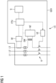
- Figure 1 shows a representation of a basic circuit diagram of an exemplary circuit breaker.
- Figure 1 shows schematically a low-voltage circuit breaker LS, with various units of the circuit breaker being shown in a housing GEH.
- Figure 1 shows electrical conductors L1, L2, L3 of a low-voltage circuit, for example a three-phase AC circuit, wherein the first conductor L1 forms the first phase, the second conductor L2 forms the second phase and the third conductor L3 forms the third phase of the three-phase AC circuit.
- a neutral conductor and a protective conductor can also be provided.
- the third conductor L3 is connected to an energy converter EW, such that at least part of the current, ie a partial conductor current, or the entire current of the third conductor flows through the primary side of the energy converter EW.
- the energy converter EW is usually a transformer with a core, for example an iron converter.
- an energy converter EW can be provided in each phase or in each conductor of the electrical circuit.
- the secondary side of the energy converter EW or each energy converter provided is connected to a power supply unit NT (or several power supplies), which provides an energy supply - ie self-supply, for example in the form of a supply voltage, for the control unit ETU, for example an electronic trip unit ETU.
- At least one additional component 9 can be connected to the control unit ETU.
- the power supply unit NT can also be connected to a first current sensor SE to supply energy to the first current sensor - if necessary.
- the first current sensor SE has at least one sensor element, for example a Rogowski coil, a measuring resistor/shunt, a Hall sensor or similar, for determining the level of the electrical current of at least one conductor of the electrical circuit.
- the level of the electrical current of each phase conductor or conductor of the electrical circuit is determined.
- the first current sensor SE is connected to the control unit ETU (electronic tripping unit ETU) and transmits to it the level of the electrical current of at least one conductor, the phase conductors or all conductors of the electrical circuit.
- ETU electronic tripping unit
- the control unit ETU can be a so-called electronic trip unit.
- the transmitted current values are compared in the control unit ETU with current limit values and/or current time period limit values, which form trigger reasons. If this is exceeded, the electrical circuit is interrupted. This can be done, for example, by providing an interruption unit UE, which is connected to the control unit ETU on the one hand and, on the other hand, has contacts K for interrupting the conductors L1, L2, L3 or other conductors of the electrical circuit. In this case, the interruption unit UE receives an interruption signal from the control unit ETU to open the contacts.
- FIG. 2 shows a first circuit diagram to explain the invention.
- An alternating current source EQ serving as an energy source supplies an energy consumer Load serving as an energy sink.
- a conductor of this circuit forms the primary side 20 of the energy converter EW.
- the conductor can have several turns of a primary coil of the energy converter EW. However, only the conductor (without a winding) can be led straight through or past a core 10 of the energy converter EW.
- the core 10 of the energy converter EW also has a secondary-side output or a secondary side with a secondary winding 15, which is formed by one or more turns of a secondary winding or coil 15.
- the two connections of the secondary winding 15 form the secondary-side output of the energy converter EW, which provides an energy supply for the two inputs of the at least one control unit ETU.
- Additional components of the power supply unit NT can be provided, which could be located in block 30, for example.
- One output is electrically connected to one input.
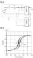
- Figure 3 shows an equivalent circuit diagram of the secondary output or the secondary winding 15 of the energy converter EW.
- the equivalent circuit of the secondary winding 15 includes a voltage source VQ (the voltage induced in the secondary winding) in series with an inductance L1 (the inductance of the secondary winding) and a resistor R1 (the wire resistance of the secondary winding).
- Figure 4 shows a representation according to Figure 3 , with the difference that a first and a second rectifier circuit D1, D2 are connected to the secondary output of the energy converter EW or to the secondary winding 15 (represented by the equivalent circuit diagram).
- the rectifier circuits D1, D2 are connected in parallel on the input side.
- the first rectifier circuit D1 is connected to the secondary winding 15 via a capacitor C1. That is, according to the invention, a capacitor or a capacitor is provided in at least one connection between the secondary winding 15 and the first rectifier circuit D1.
- the second rectifier circuit D2 is directly connected to the secondary winding 15.
- the first and second rectifier circuits D1, D2, i.e. the rectifier circuits, are connected in parallel on the output side in order to provide an energy supply for the at least one control unit ETU of the circuit breaker LS.
- a value is set for the inductive reactance XL that occurs for currents up to a first current level.
- the ETU control unit is powered by energy converters (current transformers) placed in the LS circuit breaker.
- energy converters EW have, for example, a torodial construction with a complete flow path, which is formed by, for example, the core 10 with iron material (iron core 10).
- the primary conductor of the primary side 20 is guided through, for example, a core 10 designed as a ring (toroid).
- the electromagnetic energy generated by the primary conductor is captured by the iron core 10.
- the secondary windings 15 wound around the iron core 10 convert the electromagnetic energy into electrical energy (voltage source VQ).
- the energy converter behaves differently.
- the energy converter EW operates essentially linearly.
- the property of the iron core is characterized by a curve called the BH curve, as in Figure 5 shown.
- Figure 5 shows a BH curve. This shows the amount of flux Flux (Wb) on the vertical axis generated by the iron core in response to the input line current Coil Current (AT) on the horizontal axis.
- the energy converter EW behaves like a current-dependent voltage source VQ with a series inductance L1, as shown in the equivalent circuit diagram (as well as a resistance component of the resistor R1).
- the energy converter EQ deviates from this model and behaves like a nonlinear voltage source VQ.
- the linearity of energy converters EW is used at low line currents (up to a first current level).
- more energy is extracted using a capacitor that forms a series resonant circuit, i.e. using resonance, at lower line currents (resonant capacitor C1 connected in series).
- the capacitance of the capacitor C1 cancels out the inductance L1 (of the secondary winding 15). This contributes to the fact that, according to the equivalent circuit diagram, the voltage source VQ of the secondary winding 15 directly supplies the first rectifier circuit D1 with energy, i.e. an adaptation (reduced source impedance) is achieved in order to extract higher performance for the control unit. The energy flows to the first rectifier circuit D1.
- the source impedance Z is reduced at low line currents and a higher power can be drawn from the energy converter EW. This means that even with low currents on the primary side 20, energy can be made available for a control unit ETU.
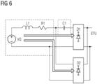
- Figure 6 shows a representation according to Figure 4 , with the energy flow drawn according to the invention.
- the capacitor C1 or the series resonant circuit from the series connection of the capacitor C1 and the inductance L1 are designed in such a way that for currents up to a first current level, the energy emitted by the energy converter EW is essentially delivered to the control unit ETU via the first rectifier circuit D1.
- the energy delivered by the energy converter EW is essentially delivered to the control unit ETU via the second rectifier circuit D2.
- An overvoltage protection element can be connected in parallel to the secondary output or the secondary winding 15 of the energy converter EW.
- the first or (and) second rectifier circuit may be a full-wave bridge rectifier circuit.
- the core 10 can be a nanocrystalline magnetic core, for example to reduce current harmonics.
- Additional components/components of the power supply unit NT can be provided.
- the invention exploits the linearity of energy converters at low currents to increase the power delivered with a capacitor. There is a dynamic change in the energy flow path with two rectifier circuits, one for resonance and one without resonance, without (significantly) increasing the complexity of the system.
- the invention thus reduces the current required on the primary side in order to provide energy (e.g. for a control unit). Two rectifier circuits connected in parallel make complicated switching mechanisms unnecessary.
Landscapes
- Rectifiers (AREA)
- Emergency Protection Circuit Devices (AREA)
- Dc-Dc Converters (AREA)
Applications Claiming Priority (1)
| Application Number | Priority Date | Filing Date | Title |
|---|---|---|---|
| DE102022209951.6A DE102022209951A1 (de) | 2022-09-21 | 2022-09-21 | Leistungsschalter |
Publications (3)
| Publication Number | Publication Date |
|---|---|
| EP4343995A2 true EP4343995A2 (fr) | 2024-03-27 |
| EP4343995A3 EP4343995A3 (fr) | 2024-04-24 |
| EP4343995B1 EP4343995B1 (fr) | 2026-04-29 |
Family
ID=87889063
Family Applications (1)
| Application Number | Title | Priority Date | Filing Date |
|---|---|---|---|
| EP23194551.0A Active EP4343995B1 (fr) | 2022-09-21 | 2023-08-31 | Disjoncteur |
Country Status (4)
| Country | Link |
|---|---|
| US (1) | US12506333B2 (fr) |
| EP (1) | EP4343995B1 (fr) |
| CN (1) | CN117747372A (fr) |
| DE (1) | DE102022209951A1 (fr) |
Citations (24)
| Publication number | Priority date | Publication date | Assignee | Title |
|---|---|---|---|---|
| DE102014217332A1 (de) | 2014-08-29 | 2016-03-03 | Siemens Aktiengesellschaft | Schaltgerät, Empfangsgerät und Verfahren |
| DE102014217292A1 (de) | 2014-08-29 | 2016-03-03 | Siemens Aktiengesellschaft | Leistungsschalter zur Unterbrechung eines Stromkreises |
| DE102015217108A1 (de) | 2014-09-18 | 2016-03-24 | Siemens Aktiengesellschaft | Niederspannungs-Leistungsschalter |
| DE102014218831A1 (de) | 2014-09-18 | 2016-03-24 | Siemens Aktiengesellschaft | Leistungsschalter |
| DE102014218910A1 (de) | 2014-09-19 | 2016-03-24 | Siemens Aktiengesellschaft | Leistungsschalter |
| DE102014224173A1 (de) | 2014-11-26 | 2016-06-02 | Siemens Aktiengesellschaft | Leistungsschalter |
| DE102015216981A1 (de) | 2014-12-18 | 2016-06-23 | Siemens Aktiengesellschaft | Leistungsschalter |
| DE102016201651A1 (de) | 2015-04-30 | 2016-11-03 | Siemens Aktiengesellschaft | Leistungsschalter |
| DE102016202827A1 (de) | 2015-05-05 | 2016-11-10 | Siemens Aktiengesellschaft | Leistungsschalter |
| DE102015226475A1 (de) | 2015-05-05 | 2016-11-10 | Siemens Aktiengesellschaft | Schalteinrichtung |
| DE102015210479A1 (de) | 2015-06-09 | 2016-12-15 | Siemens Ag | Leistungsschalter für einen elektrischen Stromkreis |
| DE102016201659A1 (de) | 2015-06-18 | 2016-12-22 | Siemens Aktiengesellschaft | Leistungsschalter |
| DE102015216023A1 (de) | 2015-08-21 | 2017-02-23 | Siemens Aktiengesellschaft | Leistungsschalter und Verfahren |
| DE102016205196A1 (de) | 2016-03-30 | 2017-10-05 | Siemens Aktiengesellschaft | Leistungsschalter |
| DE102016217425A1 (de) | 2016-09-13 | 2018-03-15 | Siemens Aktiengesellschaft | Energieversorgung |
| DE102016221093A1 (de) | 2016-10-26 | 2018-04-26 | Siemens Aktiengesellschaft | Leistungsschalter |
| DE102017201239A1 (de) | 2017-01-26 | 2018-07-26 | Siemens Aktiengesellschaft | Leistungsschalter |
| DE102017205003A1 (de) | 2017-03-24 | 2018-09-27 | Siemens Aktiengesellschaft | Leistungsschalter |
| DE102017205004A1 (de) | 2017-03-24 | 2018-09-27 | Siemens Aktiengesellschaft | Leistungsschalter |
| DE102017211900A1 (de) | 2017-07-12 | 2019-01-17 | Siemens Aktiengesellschaft | Leistungsschalter und Verfahren |
| DE102017212477A1 (de) | 2017-07-20 | 2019-01-24 | Siemens Aktiengesellschaft | Leistungsschalter und Verfahren |
| DE102017214903A1 (de) | 2017-08-25 | 2019-02-28 | Siemens Aktiengesellschaft | Leistungsschalter und Verfahren |
| DE102017214907A1 (de) | 2017-08-25 | 2019-02-28 | Siemens Aktiengesellschaft | Leistungsschalter und Verfahren |
| DE102017215820A1 (de) | 2017-09-07 | 2019-03-07 | Siemens Aktiengesellschaft | Leistungsschalter und Verfahren |
Family Cites Families (11)
| Publication number | Priority date | Publication date | Assignee | Title |
|---|---|---|---|---|
| US3526812A (en) * | 1967-04-06 | 1970-09-01 | Gen Electric | Power supply for circuit breaker tripping |
| DE29617362U1 (de) * | 1996-09-24 | 1996-12-05 | Siemens AG, 80333 München | Spannungsversorgung von elektronischen Auslöseeinrichtungen |
| US8562583B2 (en) | 2002-03-26 | 2013-10-22 | Carmel Pharma Ab | Method and assembly for fluid transfer and drug containment in an infusion system |
| DE102006022223B4 (de) * | 2006-05-11 | 2025-08-14 | Sew-Eurodrive Gmbh & Co Kg | Anlagenteil und Anlage |
| US7420355B2 (en) * | 2006-07-11 | 2008-09-02 | Artesyn Technologies, Inc. | DC-DC converter with over-voltage protection |
| US8203815B2 (en) * | 2009-05-08 | 2012-06-19 | Hamilton Sundstrand Corporation | System and method to provide transient overvoltage suppression |
| US20140160820A1 (en) * | 2012-12-10 | 2014-06-12 | Grid Sentry LLC | Electrical Current Transformer for Power Distribution Line Sensors |
| DE102014209729A1 (de) | 2014-05-22 | 2015-12-17 | Siemens Aktiengesellschaft | Vorrichtung zur kontaktlosen Übertragung von Energie |
| JP6745585B2 (ja) * | 2015-03-02 | 2020-08-26 | 富士電機株式会社 | スイッチング電源装置 |
| EP3557728A1 (fr) | 2018-04-19 | 2019-10-23 | Siemens Aktiengesellschaft | Système de récupération de puissance dynamique |
| DE102019213154B4 (de) * | 2019-08-30 | 2023-08-03 | Siemens Aktiengesellschaft | Leistungsschalter |
-
2022
- 2022-09-21 DE DE102022209951.6A patent/DE102022209951A1/de active Pending
-
2023
- 2023-08-31 EP EP23194551.0A patent/EP4343995B1/fr active Active
- 2023-09-20 CN CN202311224014.7A patent/CN117747372A/zh active Pending
- 2023-09-21 US US18/471,436 patent/US12506333B2/en active Active
Patent Citations (24)
| Publication number | Priority date | Publication date | Assignee | Title |
|---|---|---|---|---|
| DE102014217332A1 (de) | 2014-08-29 | 2016-03-03 | Siemens Aktiengesellschaft | Schaltgerät, Empfangsgerät und Verfahren |
| DE102014217292A1 (de) | 2014-08-29 | 2016-03-03 | Siemens Aktiengesellschaft | Leistungsschalter zur Unterbrechung eines Stromkreises |
| DE102015217108A1 (de) | 2014-09-18 | 2016-03-24 | Siemens Aktiengesellschaft | Niederspannungs-Leistungsschalter |
| DE102014218831A1 (de) | 2014-09-18 | 2016-03-24 | Siemens Aktiengesellschaft | Leistungsschalter |
| DE102014218910A1 (de) | 2014-09-19 | 2016-03-24 | Siemens Aktiengesellschaft | Leistungsschalter |
| DE102014224173A1 (de) | 2014-11-26 | 2016-06-02 | Siemens Aktiengesellschaft | Leistungsschalter |
| DE102015216981A1 (de) | 2014-12-18 | 2016-06-23 | Siemens Aktiengesellschaft | Leistungsschalter |
| DE102016201651A1 (de) | 2015-04-30 | 2016-11-03 | Siemens Aktiengesellschaft | Leistungsschalter |
| DE102016202827A1 (de) | 2015-05-05 | 2016-11-10 | Siemens Aktiengesellschaft | Leistungsschalter |
| DE102015226475A1 (de) | 2015-05-05 | 2016-11-10 | Siemens Aktiengesellschaft | Schalteinrichtung |
| DE102015210479A1 (de) | 2015-06-09 | 2016-12-15 | Siemens Ag | Leistungsschalter für einen elektrischen Stromkreis |
| DE102016201659A1 (de) | 2015-06-18 | 2016-12-22 | Siemens Aktiengesellschaft | Leistungsschalter |
| DE102015216023A1 (de) | 2015-08-21 | 2017-02-23 | Siemens Aktiengesellschaft | Leistungsschalter und Verfahren |
| DE102016205196A1 (de) | 2016-03-30 | 2017-10-05 | Siemens Aktiengesellschaft | Leistungsschalter |
| DE102016217425A1 (de) | 2016-09-13 | 2018-03-15 | Siemens Aktiengesellschaft | Energieversorgung |
| DE102016221093A1 (de) | 2016-10-26 | 2018-04-26 | Siemens Aktiengesellschaft | Leistungsschalter |
| DE102017201239A1 (de) | 2017-01-26 | 2018-07-26 | Siemens Aktiengesellschaft | Leistungsschalter |
| DE102017205003A1 (de) | 2017-03-24 | 2018-09-27 | Siemens Aktiengesellschaft | Leistungsschalter |
| DE102017205004A1 (de) | 2017-03-24 | 2018-09-27 | Siemens Aktiengesellschaft | Leistungsschalter |
| DE102017211900A1 (de) | 2017-07-12 | 2019-01-17 | Siemens Aktiengesellschaft | Leistungsschalter und Verfahren |
| DE102017212477A1 (de) | 2017-07-20 | 2019-01-24 | Siemens Aktiengesellschaft | Leistungsschalter und Verfahren |
| DE102017214903A1 (de) | 2017-08-25 | 2019-02-28 | Siemens Aktiengesellschaft | Leistungsschalter und Verfahren |
| DE102017214907A1 (de) | 2017-08-25 | 2019-02-28 | Siemens Aktiengesellschaft | Leistungsschalter und Verfahren |
| DE102017215820A1 (de) | 2017-09-07 | 2019-03-07 | Siemens Aktiengesellschaft | Leistungsschalter und Verfahren |
Also Published As
| Publication number | Publication date |
|---|---|
| US20240097428A1 (en) | 2024-03-21 |
| CN117747372A (zh) | 2024-03-22 |
| US12506333B2 (en) | 2025-12-23 |
| EP4343995B1 (fr) | 2026-04-29 |
| DE102022209951A1 (de) | 2024-03-21 |
| EP4343995A3 (fr) | 2024-04-24 |
Similar Documents
| Publication | Publication Date | Title |
|---|---|---|
| DE102017205003B4 (de) | Leistungsschalter | |
| DE102017205004B4 (de) | Leistungsschalter | |
| EP0152002B1 (fr) | Déphaseur | |
| DE102016217425A1 (de) | Energieversorgung | |
| EP3226013A1 (fr) | Capteur de courant différentiel | |
| EP2978090A1 (fr) | Dispositif de protection pour des reseaux d'alimentation en energie electrique, source d'energie, reseau d'alimentation en energie et utilisation d'un tel dispositif de protection | |
| EP2945257B1 (fr) | Équilibrage des tensions électriques sur les condensateurs électriques dans un circuit en série | |
| WO2008095875A1 (fr) | Convertisseur courant continu-courant alternatif sans éléments redresseurs sur le côté secondaire du transformateur | |
| EP4343995A2 (fr) | Disjoncteur | |
| CH409087A (de) | Distanzschutzrelaisanordnung mit elliptischer Auslösecharakteristik für Wechsel- oder Drehstromleitungen | |
| DE102019213154B4 (de) | Leistungsschalter | |
| AT408155B (de) | Schaltungsanordnung zur erzeugung einer versorgungsspannung | |
| DE2944812A1 (de) | Dreiwicklungstransformator | |
| DE2716605C2 (de) | Schaltungsanordnung zur ErdschluBerfassung bei einem Stromrichter | |
| WO2000067279A1 (fr) | Disjoncteur a minimum de tension | |
| EP0899845A2 (fr) | Circuit pour l'alimentation d'un aimant de déclenchement d'un disjoncteur | |
| CH450531A (de) | Anordnung zur Begrenzung von Überströmen in Hochspannungswechselstromnetzen | |
| EP2424062B1 (fr) | Appareil de coupure, en particulier disjoncteur basse tension, et dispositif de fourniture d'énergie pour une unité de déclenchement électronique d'un appareil de coupure | |
| DE279502C (fr) | ||
| EP0958642B1 (fr) | Circuiterie pour le fonctionnement d'un declencheur electronique d'un sectionneur de puissance | |
| DE640243C (de) | Anordnung zur selbsttaetigen Abschaltung eines fehlerhaften Teiles einer elektrischen Anlage | |
| AT100393B (de) | Einrichtung zum Erdschlußschutz von Hochspannungsnetzen mit geerdetem Nullpunkt. | |
| AT138264B (de) | Schaltung für Relais in Wechselstromkreisen. | |
| CH433505A (de) | Einrichtung zur Verminderung der Spannungsschwankungen bei Anschluss eines variablen Verbrauchers an ein ein- oder mehrphasiges Netz | |
| DE570835C (de) | Einrichtung zum Selektivschutz und zur Fehlerortsbestimmung fuer Wechselstromnetze |
Legal Events
| Date | Code | Title | Description |
|---|---|---|---|
| PUAI | Public reference made under article 153(3) epc to a published international application that has entered the european phase |
Free format text: ORIGINAL CODE: 0009012 |
|
| STAA | Information on the status of an ep patent application or granted ep patent |
Free format text: STATUS: THE APPLICATION HAS BEEN PUBLISHED |
|
| PUAL | Search report despatched |
Free format text: ORIGINAL CODE: 0009013 |
|
| AK | Designated contracting states |
Kind code of ref document: A2 Designated state(s): AL AT BE BG CH CY CZ DE DK EE ES FI FR GB GR HR HU IE IS IT LI LT LU LV MC ME MK MT NL NO PL PT RO RS SE SI SK SM TR |
|
| AK | Designated contracting states |
Kind code of ref document: A3 Designated state(s): AL AT BE BG CH CY CZ DE DK EE ES FI FR GB GR HR HU IE IS IT LI LT LU LV MC ME MK MT NL NO PL PT RO RS SE SI SK SM TR |
|
| RIC1 | Information provided on ipc code assigned before grant |
Ipc: H02H 3/08 20060101ALN20240318BHEP Ipc: H02H 1/06 20060101AFI20240318BHEP |
|
| STAA | Information on the status of an ep patent application or granted ep patent |
Free format text: STATUS: REQUEST FOR EXAMINATION WAS MADE |
|
| 17P | Request for examination filed |
Effective date: 20240517 |
|
| RBV | Designated contracting states (corrected) |
Designated state(s): AL AT BE BG CH CY CZ DE DK EE ES FI FR GB GR HR HU IE IS IT LI LT LU LV MC ME MK MT NL NO PL PT RO RS SE SI SK SM TR |
|
| STAA | Information on the status of an ep patent application or granted ep patent |
Free format text: STATUS: EXAMINATION IS IN PROGRESS |
|
| 17Q | First examination report despatched |
Effective date: 20241016 |
|
| GRAP | Despatch of communication of intention to grant a patent |
Free format text: ORIGINAL CODE: EPIDOSNIGR1 |
|
| STAA | Information on the status of an ep patent application or granted ep patent |
Free format text: STATUS: GRANT OF PATENT IS INTENDED |
|
| RIC1 | Information provided on ipc code assigned before grant |
Ipc: H02H 1/06 20060101AFI20251211BHEP Ipc: H02H 3/08 20060101ALN20251211BHEP |
|
| INTG | Intention to grant announced |
Effective date: 20251222 |
|
| GRAS | Grant fee paid |
Free format text: ORIGINAL CODE: EPIDOSNIGR3 |
|
| GRAA | (expected) grant |
Free format text: ORIGINAL CODE: 0009210 |
|
| STAA | Information on the status of an ep patent application or granted ep patent |
Free format text: STATUS: THE PATENT HAS BEEN GRANTED |
|
| AK | Designated contracting states |
Kind code of ref document: B1 Designated state(s): AL AT BE BG CH CY CZ DE DK EE ES FI FR GB GR HR HU IE IS IT LI LT LU LV MC ME MK MT NL NO PL PT RO RS SE SI SK SM TR |
|
| REG | Reference to a national code |
Ref country code: CH Ref legal event code: F10 Free format text: ST27 STATUS EVENT CODE: U-0-0-F10-F00 (AS PROVIDED BY THE NATIONAL OFFICE) Effective date: 20260429 |