EP4344359A1 - Imagerie avec commutation kvp - Google Patents
Imagerie avec commutation kvp Download PDFInfo
- Publication number
- EP4344359A1 EP4344359A1 EP22197022.1A EP22197022A EP4344359A1 EP 4344359 A1 EP4344359 A1 EP 4344359A1 EP 22197022 A EP22197022 A EP 22197022A EP 4344359 A1 EP4344359 A1 EP 4344359A1
- Authority
- EP
- European Patent Office
- Prior art keywords
- ray tube
- focal spot
- synchronization signal
- sync
- high voltage
- Prior art date
- Legal status (The legal status is an assumption and is not a legal conclusion. Google has not performed a legal analysis and makes no representation as to the accuracy of the status listed.)
- Withdrawn
Links
- 238000003384 imaging method Methods 0.000 title claims abstract description 46
- 230000010354 integration Effects 0.000 claims abstract description 70
- 238000000034 method Methods 0.000 claims abstract description 36
- 238000000701 chemical imaging Methods 0.000 claims abstract description 30
- 238000002591 computed tomography Methods 0.000 claims description 14
- 238000012545 processing Methods 0.000 claims description 13
- 238000005259 measurement Methods 0.000 claims description 10
- 230000008859 change Effects 0.000 claims description 7
- 238000004590 computer program Methods 0.000 claims description 4
- 230000007704 transition Effects 0.000 description 16
- 230000003595 spectral effect Effects 0.000 description 12
- 238000010894 electron beam technology Methods 0.000 description 11
- 230000001360 synchronised effect Effects 0.000 description 10
- 230000005855 radiation Effects 0.000 description 8
- 238000010586 diagram Methods 0.000 description 7
- 239000000463 material Substances 0.000 description 5
- 230000006978 adaptation Effects 0.000 description 4
- 238000004891 communication Methods 0.000 description 4
- 230000001419 dependent effect Effects 0.000 description 4
- 238000013016 damping Methods 0.000 description 3
- 238000001228 spectrum Methods 0.000 description 3
- 230000001960 triggered effect Effects 0.000 description 3
- 230000001934 delay Effects 0.000 description 2
- 238000010438 heat treatment Methods 0.000 description 2
- 238000004519 manufacturing process Methods 0.000 description 2
- 238000002360 preparation method Methods 0.000 description 2
- 230000008569 process Effects 0.000 description 2
- 230000006641 stabilisation Effects 0.000 description 2
- 238000011105 stabilization Methods 0.000 description 2
- 238000010521 absorption reaction Methods 0.000 description 1
- 210000003484 anatomy Anatomy 0.000 description 1
- 230000015572 biosynthetic process Effects 0.000 description 1
- 238000006243 chemical reaction Methods 0.000 description 1
- 238000013461 design Methods 0.000 description 1
- 238000009826 distribution Methods 0.000 description 1
- 230000000977 initiatory effect Effects 0.000 description 1
- 230000003993 interaction Effects 0.000 description 1
- 238000000926 separation method Methods 0.000 description 1
Images






Classifications
-
- H—ELECTRICITY
- H05—ELECTRIC TECHNIQUES NOT OTHERWISE PROVIDED FOR
- H05G—X-RAY TECHNIQUE
- H05G1/00—X-ray apparatus involving X-ray tubes; Circuits therefor
- H05G1/08—Electrical details
- H05G1/26—Measuring, controlling or protecting
- H05G1/30—Controlling
- H05G1/32—Supply voltage of the X-ray apparatus or tube
-
- H—ELECTRICITY
- H05—ELECTRIC TECHNIQUES NOT OTHERWISE PROVIDED FOR
- H05G—X-RAY TECHNIQUE
- H05G1/00—X-ray apparatus involving X-ray tubes; Circuits therefor
- H05G1/08—Electrical details
- H05G1/26—Measuring, controlling or protecting
- H05G1/30—Controlling
- H05G1/34—Anode current, heater current or heater voltage of X-ray tube
-
- H—ELECTRICITY
- H05—ELECTRIC TECHNIQUES NOT OTHERWISE PROVIDED FOR
- H05G—X-RAY TECHNIQUE
- H05G1/00—X-ray apparatus involving X-ray tubes; Circuits therefor
- H05G1/08—Electrical details
- H05G1/26—Measuring, controlling or protecting
- H05G1/30—Controlling
- H05G1/46—Combined control of different quantities, e.g. exposure time as well as voltage or current
-
- H—ELECTRICITY
- H05—ELECTRIC TECHNIQUES NOT OTHERWISE PROVIDED FOR
- H05G—X-RAY TECHNIQUE
- H05G1/00—X-ray apparatus involving X-ray tubes; Circuits therefor
- H05G1/08—Electrical details
- H05G1/60—Circuit arrangements for obtaining a series of X-ray photographs or for X-ray cinematography
-
- A—HUMAN NECESSITIES
- A61—MEDICAL OR VETERINARY SCIENCE; HYGIENE
- A61B—DIAGNOSIS; SURGERY; IDENTIFICATION
- A61B6/00—Apparatus or devices for radiation diagnosis; Apparatus or devices for radiation diagnosis combined with radiation therapy equipment
- A61B6/40—Arrangements for generating radiation specially adapted for radiation diagnosis
- A61B6/405—Source units specially adapted to modify characteristics of the beam during the data acquisition process
-
- A—HUMAN NECESSITIES
- A61—MEDICAL OR VETERINARY SCIENCE; HYGIENE
- A61B—DIAGNOSIS; SURGERY; IDENTIFICATION
- A61B6/00—Apparatus or devices for radiation diagnosis; Apparatus or devices for radiation diagnosis combined with radiation therapy equipment
- A61B6/48—Diagnostic techniques
- A61B6/482—Diagnostic techniques involving multiple energy imaging
Definitions
- the invention relates to imaging with an imaging system using kVp switching, and in particular to controlling operation of an X-ray tube with a high voltage generator assembly for spectral imaging.
- a computed tomography (CT) scanner generally includes an X-ray tube mounted on a rotatable gantry opposite one or more rows of detectors.
- the X-ray tube rotates around an examination region located between the X-ray tube and the one or more rows of detectors and emits broadband radiation that traverses the examination region. Electrical power is supplied to the X-ray tube with a high voltage generator.
- the one or more rows of detectors detect radiation that traverses the examination region and generate projection data indicative thereof.
- a reconstructor reconstructs the projection data to generate volumetric image data, which can be displayed, filmed, archived, conveyed to another device, etc.
- the detector array includes detector pixels that convert detected x-ray photons into electrical signals indicative thereof. For each revolution of the rotating gantry, the detector pixels detect and convert x-ray photons for a plurality of integration periods, each corresponding to a different angular position range. The time duration of an integration period depends on the rotating gantry rotation speed and the number integration periods for each revolution of the scan. With an integrating detector array, at the beginning of each integration period, the integrators for the detector pixels are reset, and then the integrators receive and integrate the electrical signals over the integration period. The integrated signals form the projection data for that integration period.
- the X-ray tube typically includes a cathode with a filament and an anode.
- a filament current is applied to the filament, which heats the filament, causing the filament to expel electrons (thermionic emission), creating a space charge (or cloud a negative charge) a short distance away from the filament.
- a peak tube voltage (kVp) is applied across the cathode and the anode and causes a beam of the electrons to accelerate from the cathode and impinge the anode.
- Electrostatic or magnetic focusing with e.g. grid electrodes or quadrupoles can be applied to control a size of and steer the beam of electrons.
- An interaction of the electrons with the material of the anode produces heat and radiation, including X-rays, which pass through a tube window, into an examination region, to a detector.
- a surface area of the anode that receives the beam of electrons is referred to as a focal spot.
- the size of the focal spot is one factor that affects the image quality of the volumetric image data.
- the focal spot size affects the spatial resolution, where a smaller focal spot size results in a greater spatial resolution than a larger focal spot size, e.g., due to less focal spot blur from geometric magnification.
- the size of the focal spot may depend on the X-ray tube voltage, beam focusing voltage and tube current.
- the voxels of the volumetric image data are displayed using gray scale values corresponding to relative radiodensity.
- the gray scale values reflect the attenuation characteristics of the scanned subject and represent anatomical structures.
- the detected radiation also includes spectral information as the absorption of a photon by a material of a subject and/or an object is dependent on the energy of the photon traversing the material. Such spectral information provides additional information such as information indicative of the atomic, elemental or material composition of the material.
- the projection data does not reflect the spectral characteristics as the projection data are proportional to the energy fluence integrated over the energy spectrum (e.g., 40 keV to 120 keV), and the volumetric image data will not reflect the energy dependent information.
- a CT scanner configured for spectral (multi/dual-energy) imaging leverages the spectral characteristics in the detected radiation to provide further information such as atomic or elemental composition information.
- a spectral CT scanner is configured to detect different bands of X-ray radiation (instead of just the entire spectrum) and generate projection data for each of the different energy bands (instead of just the entire spectrum). In one instance, this is achieved through so called kVp switching.
- the X-ray tube voltage i.e. the kVp
- the kVp may be switched back and forth between two kVp's, such as between a first 80 kVp for odd number data acquisition periods and a second 140 kVp for even number data acquisition periods, or vice versa.
- Spectral imaging using fast kVp switching in the high voltage generator may be a promising cost-effective alternative to e.g. spectral imaging with multi-layer energy discriminating scintillator or direct conversion detectors
- a computer-implemented method for controlling operation of an X-ray tube with a high voltage generator assembly for spectral imaging with an imaging system comprises:
- the proposed method may advantageously reduce complexity of spectral imaging with kVp switching in the high voltage generator by processing a common synchronization signal to synchronize both the kVp switching cycle as well as control of focal spot characteristics with information about detector integrations.
- Data communication between the high voltage generator assembly and other parts of the imaging system may therefore be simplified. This can be particularly advantageous for systems where the high voltage generator assembly is already configured to synchronize the X-ray tube focal spot with the detector integration periods, e.g. during an imaging scan.
- a spectral imaging function may be achieved with minor adaptations.
- An X-ray tube kVp switching cycle includes switching and the transitions between at least two kVp's, such as from 80 kV to 140 kV and back to 80 kV to complete one cycle.
- a cycle includes at least four phases such as a low plateau kVp, a transition from low to high, a high plateau kVp and a transition from high back to low.
- the quality of spectral imaging data reconstruction depends on the spectral separation of applied x-ray in the integration periods with different kVp's as well as the reproducibility of the spectral x-ray distribution in the integration periods with the same kVp. For both conditions, a good synchronization of the kVp switching cycles with the detector integration is important. At the same time, the focal spot control must be well synchronized with the integration periods, on the one hand to keep the focal spot size constant when changing the kVp and on the other hand a good synchronization is a prerequisite for a clear assignment of the different focal spot positions to the integration periods that finally determines spatial resolution.
- the synchronization of the detector integration period with the X-ray tube kVp switching cycle comprises controlling of a tube voltage
- the synchronization of the detector integration period with the X-ray tube focal spot size and/or focal spot position comprises controlling of a focusing current/voltage (FS).
- a synchronization signal such as a synchronization pulse, may advantageously trigger control or adaptation of a tube voltage from the high voltage generator to e.g. initiate or maintain or end a phase of a kVp switching cycle.
- the focal spot size and/or focal spot position can be adapted or maintained in sync with the detector integration period.
- the method further comprises:
- Voltage switching during the spectral imaging scan typically consists of a fast repetition of a tube voltage switch sequence.
- the detector integrations are synchronized with this sequence.
- the common synchronization signal may be used to e.g. trigger the start of each sequence, thereby avoiding a need to continuously encode and communicate each stage of the switching cycle.
- the method further comprises:
- the method further comprises synchronizing, based on the synchronization signal, an X-ray tube emission current measurement with the detector integration period.
- the emission current of the X-ray tube may change when the tube voltage changes and be superimposed by loading currents of the damping capacitance during tube voltage transitions.
- the accuracy of emission current measurement may thereby be negatively affected during voltage transitions.
- the synchronization signal depends on an angular position of a rotating imaging system gantry.
- the synchronization signal is communicated between the imaging system and the high voltage generator assembly through a single digital signal line.
- the method further comprises introducing a delay between the synchronization signal and a change in an X-ray tube voltage HV and/or a change in a focusing current/voltage FS.
- a delay between the synchronization signal and a change in an X-ray tube voltage HV and/or a change in a focusing current/voltage FS it may be advantageous to introduce a constant or dynamic delay between a synchronization pulse and the kVp switching and/or change of the focal spot characteristics, in order to optimize imaging. E.g. to adjust the focal spot for kVp ramp up and ramp down phases during a switching cycle.
- a computer program element which, when being executed by a processing unit, is adapted to cause the processing unit to perform the method according to any of the methods as described above.
- a high voltage generator assembly for controlling operation of an X-ray tube for spectral imaging, wherein the high voltage generator assembly is adapted to be connected to the X-ray tube, and the high voltage generator assembly comprises a processing unit configured to carry out any of the methods as described above.
- an imaging system for spectral imaging comprising the high voltage generator assembly as mentioned above.
- the imaging system is a computed tomography system.
- the X-ray tube 100 includes a cathode with a filament 101.
- a filament current or heating current 102 is applied to the filament 101, causing the filament 101 to expel electrons through thermionic emission.
- the heating current 102 may be controlled with a high voltage generator 200 as shown in Fig. 2 .
- a tube voltage HV from the high voltage generator 200 is applied in order to accelerate emitted electrons from the cathode filament 101 such that the electrons impinge a rotating anode 106 at a focal spot 103 and generate X-ray radiation 107.
- the X-ray tube 100 further includes electron beam optics 104, which regulates the size and position of the electron beam 105 between the filament 101 and the anode 106.
- the electron beam optics regulates the focal spot 103 size and/or shape and/or position.
- the electron beam optics 103 is controlled by the high voltage generator 200 via a focusing current or voltage FS.
- the tube voltage HV and the focusing current/voltage FS are controlled by the high voltage generator 200 for X-ray generation with the X-ray tube 100.
- the electron beam optics 103 in Fig. 1 may be e.g. quadrupoles or other means for magnetic electron beam focusing and positioning and/or grid electrodes for electrostatic focusing and positioning.
- Fig. 2 schematically illustrates a high voltage generator 200, according to an embodiment of the invention.
- the high voltage generator 200 comprises an interface unit IU, capable of processing data.
- the interface unit IU may comprise a processing unit.
- the high voltage generator 200 may receive and/or communicate control parameters regarding aspects such as, but not limited to, tube peak voltage (kVp), kVp shape, emission current, focal spot size, position etc.
- the control interface CTRL may be directly interfacing with an imaging system 300, such as illustrated in Fig. 3 , or with other user interfaces, such as via a local or remote computer interface etc. to program the high voltage generator 200.
- the high voltage generator 200 is also configured to receive a synchronization signal SYNC from an imaging system 300, where the synchronization signal is timed to detector integration periods.
- the synchronization signal SYNC may comprise e.g. synchronization pulses.
- the high voltage generator 200 processes the synchronization signal SYNC to generate an output tube voltage HV, with a power block PB, for the X-ray tube 100 such that an X-ray tube kVp switching cycle is synchronized with the detector integration period.
- the power block PB may also control the tube current and filament current 102.
- the high voltage generator 200 also processes the synchronization signal SYNC to generate a focusing current/voltage FS such that control of the X-ray tube focal spot size and/or position with the X-ray tube electron beam optics 104 is synchronized with the detector integration period.
- a focusing current/voltage FS such that control of the X-ray tube focal spot size and/or position with the X-ray tube electron beam optics 104 is synchronized with the detector integration period.
- the signal for the electron beam optics 104 is generated with a deflection unit DFU that may drive electromagnetic electron beam optics 104 in the X-ray tube with a focusing current FS.
- the HV generator 200 might individually add delays 201, 202 to the adjustments of tube voltage HV and/or focusing current FS, e.g. in order to minimize focal spot size deviations during kVp transitions.
- SYNC single synchronization signal
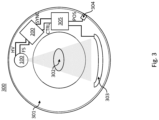
- Fig. 3 illustrates an imaging system 300, such as a Computed Tomography (CT) system, according to an embodiment of the invention.
- the system includes an X-ray tube 100 mounted on a rotatable gantry 301.
- the X-ray tube 100 is located opposite to a detector 303.
- the X-ray tube 100 can rotate around an examination region with an imaging subject 302. X-rays from the X-ray tube 100 traverses the examination region and are detected with the detector 303.
- the imaging system 300 further includes a high voltage generator 200, an imaging system controller 305 and an encoder 304.
- the encoder 304 determines the angular position of the X-ray tube 100 and detector 303 and provides an angular position signal POS to the imaging system controller 305.
- the imaging system controller 305 is connected to the high voltage generator 200 and can communicate with the high voltage generator via a control interface CTRL.
- the imaging system controller 305 generates a synchronization signal SYNC that relates to a detector integration period, i.e. a period of time when the detector 303 detects radiation, e.g. while rotating through a predetermined angular increment during a scan.
- the imaging system controller 305 may take the angular position of the X-ray tube 100 and the detector 303 into account when generating the synchronization signal SYNC, since the angular position signal POS is communicated between the encoder 304 and the imaging system controller 305. Based on the synchronization signal SYNC, the voltage generator 200 generates a tube voltage HV and focusing current/voltage FS such that at least the kVp switching cycle and control of the X-ray tube focal spot size and/or position is synchronized with the detector integration period.
- the kVp switching sequence is pre-defined.
- the imaging system controller 305 sends a predefined kVp switching sequence to the high voltage generator 200 via the control interface CTRL.
- the switching sequence is communicated to the high voltage generator 200 via another interface, internal or external to the system 300.
- the predefined sequence defines the length high voltage phases in multiples of detector integration periods.
- the imaging system controller 305 synchronizes the tube voltage switching with the detector integration periods via the synchronization signal SYNC. E.g. by sending synchronization pulses to the high voltage generator 200 via a single digital signal line. Triggered by the synchronization pulses the high voltage generator 200 starts ramping up and down, possibly with a delay 202, the tube voltage HV in a way that reproduces the predefined kVp switching sequence.
- a sequence of focal spot sizes and/or focal spot positions may be pre-defined in multiples of detector integration periods.
- the imaging system controller 305 sends a predefined focal spot sequence to the high voltage generator 200 During the scan, the imaging system controller 305 synchronizes the focal spot control with the detector integration periods via the synchronization signal SYNC. E.g. by sending synchronization pulses to the high voltage generator 200 via a single digital signal line. Triggered by the synchronization pulses the high voltage generator starts controlling the size and/or position of the focal spot with the focusing current/voltage FS such that the control of the focal spot reproduces the predefined focal spot sequence.
- Emission current of an X-ray tube 100 needs to be monitored in order to ensure patient safety, for example with respect to the X-ray dose, for avoiding tube overloading, etc.
- the tube peak voltage is ramped up and down repeatedly at a high rate.
- the detector integrations may be limited to phases of the scan in which the tube voltage HV is stable or to phases in which the voltage changes reproducibly during the tube voltage transitions.
- the emission current also changes when the tube voltage changes and is superimposed by loading currents of the damping capacitance during the tube voltage transitions. The accuracy of emission current measurements may therefore be improved by limiting the measurement to those phases of kVp switching imaging scans in which the detector integration is active.
- the synchronization signal SYNC between the imaging system controller 305 and the high voltage generator 200 is also used to limit the emission current measurement to those scan phases with active detector integration and to mask out parts of the tube voltage transitions that have a negative impact on the emission current measurement.
- the X-ray generator 200 may need to introduce specific delays for one or both of the functions.
- Fig. 4 illustrates a sequence diagram of kVp switching according to an embodiment of the invention.
- the diagram shows the communication between the imaging system controller 305 and the high voltage generator 200 during an X-ray exposure such as a CT spectral scan.
- the CT system controller 305 may send exposure parameters to the high voltage generator 200, e.g. via the control interface CTRL:
- Parameters may include information such as, but not limited to, planned tube voltage and tube current (typical values for low and high kVp are 80 kV and 140 kV); focal spot size; focal spot position vector; the tube voltage (kVp) shape/waveform etc.
- the waveform e.g.
- each of the four phases consists of 4 phases: Plateau at low kVp, transition to high kVp, plateau at high kVp and transition back to low kVp.
- the length of each of the four phases is given in one or several detector integration periods.
- An integration period depends on the gantry rotation speed.
- a detector integration period may be on the order of magnitude of 100 ⁇ s at full gantry speed.
- Example times for the four kVp phases are 1000 ⁇ s for the plateaus and 300 to 400 ⁇ s for the transitions.
- transition times may be significantly different depending on changes in the system hardware, such as transition times may be significantly reduced with hardware changes like quadrupole boosting and/or a reduced high voltage damping capacitance.
- the high voltage generator 200 adjusts the filament current 102 to start exposure with the selected tube current.
- the high voltage generator 200 adjusts the electron optics currents FS for the selected focal spot size at the initial position.
- the CT system controller 305 sends synchronization pulses SYNC, which triggers focal spot position adaptation with the focusing current FS and kVp changes with tube voltage HV adaptations, following the predefined sequences.
- Electron optic currents FS for given tube voltage HV and current and focal spot position and size may be taken from a look up table (LUT).
- the LUT may be prepared individually for each X-ray tube or bundle of X-ray tube 100 and high voltage generator 200 during production.
- the LUT may be prepared or adapted after production and communicated with the high voltage generator 200 via a suitable control interface.
- Fig. 5 illustrates a timing diagram according to an embodiment of the invention.
- the timing diagram shows the synchronization between the imaging system 300 and the interface unit IU of the high voltage generator 200, the step from interface unit UI to deflection unit DFU and power block PB, the resulting focusing current FS, focal spot position and tube voltage HV, as well as detector integration at the system level.
- the imaging system controller 305 of the imaging system 300 sends a synchronization trigger pulse SYNC to the interface unit IU ahead in time of the detector integration period, such as e.g. 50 to 100 ⁇ s before the beginning of the next integration period, to grant the high voltage generator 200 time to prepare the adjustments.
- a synchronization trigger pulse SYNC to the interface unit IU ahead in time of the detector integration period, such as e.g. 50 to 100 ⁇ s before the beginning of the next integration period, to grant the high voltage generator 200 time to prepare the adjustments.
- the system may indicate the start of the change in focal spot position and initiation of the kVp sequence by a long SYNC pulse.
- the focal spot position vector and the kVp sequence have the same size/length.
- the X-ray exposure starts with e.g. a 20 to 40 ms tube current stabilization phase, at the very left of the timing diagram. Processing and forwarding of the SYNC pulses to the deflection unit DFU and the power block PB start with the first long pulse after this stabilization phase.
- the high voltage generator 200 might individually delay the adjustments of tube voltage HV and/or focusing currents FS in order to minimize focal spot size deviations during the kVp transitions.
- the emission current measurements are synchronized by the high voltage generator 200, based on the synchronization pulses SYNC.
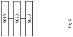
- Fig. 6 shows a flowchart representing a method for controlling operation of an X-ray tube, according to an embodiment of the invention. The method comprises:
- Fig. 7 shows a flowchart representing a method for controlling operation of an X-ray tube with a predefined voltage switching sequence, according to an embodiment of the invention.
- the method comprises
- Fig. 8 shows a flowchart representing a method for controlling operation of an X-ray tube with a predefined focal spot characteristic, according to an embodiment of the invention.
- the method comprises:
Landscapes
- Health & Medical Sciences (AREA)
- General Health & Medical Sciences (AREA)
- Toxicology (AREA)
- Apparatus For Radiation Diagnosis (AREA)
- X-Ray Techniques (AREA)
Priority Applications (2)
| Application Number | Priority Date | Filing Date | Title |
|---|---|---|---|
| EP22197022.1A EP4344359A1 (fr) | 2022-09-22 | 2022-09-22 | Imagerie avec commutation kvp |
| PCT/EP2023/074949 WO2024061683A2 (fr) | 2022-09-22 | 2023-09-12 | Imagerie avec commutation kvp |
Applications Claiming Priority (1)
| Application Number | Priority Date | Filing Date | Title |
|---|---|---|---|
| EP22197022.1A EP4344359A1 (fr) | 2022-09-22 | 2022-09-22 | Imagerie avec commutation kvp |
Publications (1)
| Publication Number | Publication Date |
|---|---|
| EP4344359A1 true EP4344359A1 (fr) | 2024-03-27 |
Family
ID=83438267
Family Applications (1)
| Application Number | Title | Priority Date | Filing Date |
|---|---|---|---|
| EP22197022.1A Withdrawn EP4344359A1 (fr) | 2022-09-22 | 2022-09-22 | Imagerie avec commutation kvp |
Country Status (2)
| Country | Link |
|---|---|
| EP (1) | EP4344359A1 (fr) |
| WO (1) | WO2024061683A2 (fr) |
Citations (1)
| Publication number | Priority date | Publication date | Assignee | Title |
|---|---|---|---|---|
| US20180068823A1 (en) * | 2016-09-07 | 2018-03-08 | General Electric Company | X-ray tube with gridding electrode |
Family Cites Families (1)
| Publication number | Priority date | Publication date | Assignee | Title |
|---|---|---|---|---|
| JP2013144038A (ja) * | 2012-01-16 | 2013-07-25 | Toshiba Corp | X線ct装置 |
-
2022
- 2022-09-22 EP EP22197022.1A patent/EP4344359A1/fr not_active Withdrawn
-
2023
- 2023-09-12 WO PCT/EP2023/074949 patent/WO2024061683A2/fr not_active Ceased
Patent Citations (1)
| Publication number | Priority date | Publication date | Assignee | Title |
|---|---|---|---|---|
| US20180068823A1 (en) * | 2016-09-07 | 2018-03-08 | General Electric Company | X-ray tube with gridding electrode |
Also Published As
| Publication number | Publication date |
|---|---|
| WO2024061683A3 (fr) | 2024-05-02 |
| WO2024061683A2 (fr) | 2024-03-28 |
Similar Documents
| Publication | Publication Date | Title |
|---|---|---|
| EP2271189B1 (fr) | Modulation grande vitesse d'un tube à rayons x à foyer commuté | |
| US7295651B2 (en) | Stationary computed tomography system and method | |
| US10405813B2 (en) | Panoramic imaging using multi-spectral X-ray source | |
| EP3294044B1 (fr) | Tube à rayons x avec électrode de maillage | |
| CN102548174B (zh) | 用于操作电子束系统的方法和系统 | |
| US20090154649A1 (en) | X-ray tube whose electron beam is manipulated synchronously with the rotational anode movement | |
| JP5568413B2 (ja) | X線を発生させるためのシステム及び方法 | |
| JP4267180B2 (ja) | X線ct装置 | |
| CN107110796B (zh) | 具有恒定能量间隔的能量成像 | |
| CN113841044B (zh) | 在kVp切换谱(多能量)成像扫描期间维持给定焦斑尺寸 | |
| EP4344359A1 (fr) | Imagerie avec commutation kvp | |
| US20030210764A1 (en) | Pulsed power application for x-ray tube | |
| EP4387400A1 (fr) | Détermination du courant d'un tube à rayons x | |
| EP4391729A1 (fr) | Commande d'optique de faisceau d'électrons de tube à rayons x pendant une commutation kvp | |
| US20250288260A1 (en) | X-ray ct apparatus, controller of x-ray ct apparatus, and control method for x-ray ct apparatus | |
| EP4623830A1 (fr) | Procédé de réalisation d'une imagerie spectrale par tomodensitométrie, programme informatique, système de tomodensitométrie, utilisation d'une technologie de point focal volant |
Legal Events
| Date | Code | Title | Description |
|---|---|---|---|
| PUAI | Public reference made under article 153(3) epc to a published international application that has entered the european phase |
Free format text: ORIGINAL CODE: 0009012 |
|
| STAA | Information on the status of an ep patent application or granted ep patent |
Free format text: STATUS: THE APPLICATION HAS BEEN PUBLISHED |
|
| AK | Designated contracting states |
Kind code of ref document: A1 Designated state(s): AL AT BE BG CH CY CZ DE DK EE ES FI FR GB GR HR HU IE IS IT LI LT LU LV MC MK MT NL NO PL PT RO RS SE SI SK SM TR |
|
| STAA | Information on the status of an ep patent application or granted ep patent |
Free format text: STATUS: THE APPLICATION IS DEEMED TO BE WITHDRAWN |
|
| 18D | Application deemed to be withdrawn |
Effective date: 20240928 |