EP4391729A1 - Commande d'optique de faisceau d'électrons de tube à rayons x pendant une commutation kvp - Google Patents
Commande d'optique de faisceau d'électrons de tube à rayons x pendant une commutation kvp Download PDFInfo
- Publication number
- EP4391729A1 EP4391729A1 EP22215748.9A EP22215748A EP4391729A1 EP 4391729 A1 EP4391729 A1 EP 4391729A1 EP 22215748 A EP22215748 A EP 22215748A EP 4391729 A1 EP4391729 A1 EP 4391729A1
- Authority
- EP
- European Patent Office
- Prior art keywords
- tube
- electron beam
- ray tube
- voltage
- current
- Prior art date
- Legal status (The legal status is an assumption and is not a legal conclusion. Google has not performed a legal analysis and makes no representation as to the accuracy of the status listed.)
- Withdrawn
Links
Images



Classifications
-
- H—ELECTRICITY
- H05—ELECTRIC TECHNIQUES NOT OTHERWISE PROVIDED FOR
- H05G—X-RAY TECHNIQUE
- H05G1/00—X-ray apparatus involving X-ray tubes; Circuits therefor
- H05G1/08—Electrical details
- H05G1/58—Switching arrangements for changing-over from one mode of operation to another, e.g. from radioscopy to radiography, from radioscopy to irradiation or from one tube voltage to another
-
- H—ELECTRICITY
- H05—ELECTRIC TECHNIQUES NOT OTHERWISE PROVIDED FOR
- H05G—X-RAY TECHNIQUE
- H05G1/00—X-ray apparatus involving X-ray tubes; Circuits therefor
- H05G1/08—Electrical details
- H05G1/26—Measuring, controlling or protecting
- H05G1/30—Controlling
- H05G1/52—Target size or shape; Direction of electron beam, e.g. in tubes with one anode and more than one cathode
Definitions
- the invention relates to the field of X-ray, and more specifically to a method of controlling electron beam optics of an X-ray tube during kVp switching, to a computer program element, to a computer readable medium, to a controller configured to carry out the method and to an X-ray system comprising the controller.
- a computed tomography (CT) scanner generally includes an X-ray tube mounted on a rotatable gantry opposite one or more rows of detectors.
- the X-ray tube rotates around an examination region located between the X-ray tube and the one or more rows of detectors and emits broadband radiation that traverses the examination region. Electrical power is supplied to the X-ray tube with a high voltage generator.
- the one or more rows of detectors detect radiation that traverses the examination region and generate projection data indicative thereof.
- a reconstructor reconstructs the projection data to generate volumetric image data, which can be displayed, filmed, archived, conveyed to another device, etc.
- the detector array includes detector pixels that convert detected x-ray photons into electrical signals indicative thereof. For each revolution of the rotating gantry, the detector pixels detect and convert x-ray photons for a plurality of integration periods, each corresponding to a different angular position range. The time duration of an integration period depends on the rotating gantry rotation speed and the number integration periods for each revolution of the scan. With an integrating detector array, at the beginning of each integration period, the integrators for the detector pixels are reset, and then the integrators receive and integrate the electrical signals over the integration period. The integrated signals form the projection data for that integration period.
- the X-ray tube typically includes a cathode with a filament and an anode.
- a filament current is applied to the filament, which heats the filament, causing the filament to expel electrons (thermionic emission), creating a space charge (or cloud a negative charge) a short distance away from the filament.
- a peak tube voltage (kVp) is applied across the cathode and the anode and causes a beam of the electrons to accelerate from the cathode and impinge the anode.
- the X-ray tube current, or emission current represents the number of electrons per second flowing from the cathode to the anode. Electrostatic or magnetic focusing with e.g.
- grid electrodes or quadrupoles can be applied to control a size of and steer the beam of electrons.
- An interaction of the electrons with the material of the anode produces heat and radiation, including X-rays, which pass through a tube window, into an examination region, to a detector.
- a surface area of the anode that receives the beam of electrons is referred to as a focal spot.
- the size of the focal spot is one factor that affects the image quality of the volumetric image data.
- the focal spot size affects the spatial resolution, where a smaller focal spot size results in a greater spatial resolution than a larger focal spot size, e.g., due to less focal spot blur from geometric magnification.
- the size of the focal spot may depend on the X-ray tube voltage, beam focusing voltage and tube current.
- the voxels of the volumetric image data are displayed using gray scale values corresponding to relative radiodensity.
- the gray scale values reflect the attenuation characteristics of the scanned subject and represent anatomical structures.
- the detected radiation also includes spectral information as the absorption of a photon by a material of a subject and/or an object is dependent on the energy of the photon traversing the material. Such spectral information provides additional information such as information indicative of the atomic, elemental or material composition of the material.
- the projection data does not reflect the spectral characteristics as the projection data are proportional to the energy fluence integrated over the energy spectrum (e.g., 40 keV to 120 keV), and the volumetric image data will not reflect the energy dependent information.
- Spectral imaging using fast kVp switching in the high voltage generator may be a promising cost-effective alternative to e.g. spectral imaging with multi-layer energy discriminating scintillator or direct conversion detectors.
- Focal spot size deviations during fast kVp switching X-ray tube voltage transitions can negatively affect image quality or can even damage the tube. Therefore, the focal spot is preferably kept stable during such transitions and fast and precise control of electron beam optics is required.
- a computer-implemented method of controlling electron beam optics of an X-ray tube during X-ray kVp switching comprises:
- the invention makes it possible to control the electron beam optics, such as magnetic and/or electrostatic electron beam optics that regulate the focal spot position and/or size, during very rapid changes of the tube voltage and tube emission current.
- the tube voltage and filament current as known input parameters, the tube emission current and subsequently the suitable electron beam focusing current and/or voltage may be determined such that an electron beam optics signal can be output in a timely manner.
- a kVp switching cycle of an X-ray tube comprises two or more different kVp energy levels. With corresponding measurement intervals (integration periods) at the different kVp energy levels, this may enable X-ray spectral imaging.
- the tube voltage is switched between at least a "high" kVp energy level and a "low” kVp energy level, such that the X-ray tube generates at least two different X-ray spectra.
- the generator and X-ray tube hold the cathode to anode voltage at a "low" voltage of for example 80 kV for a time period and then ramps the cathode to anode voltage to a "high" voltage of for example 140 kV over a time period, and then holds the cathode to anode voltage at 140 kV for a time period, thereby forming a cycle over which dual energy X-ray are produced and providing for spectral imaging.
- the cycle times may be on the order of tenths to hundreds of microseconds. Hence, transitions of tube voltage and emission current is very rapid. Transition times between energy levels may be shorter than 300/ls, such as between 30 ⁇ s and 300 ⁇ s, or even shorter.
- a computer-implemented method means a method which involves the use of a processor, which may include a computer, a computer network, and/or another programmable apparatus, such as a single and/or multi core processing unit, a graphics processing unit, an accelerated processing unit, a digital signal processor, a field programmable gate array, and/or an application-specific integrated circuit, etc.
- the method may be carried out involving a single apparatus, such as e.g. a single controller comprising and/or interacting with a processor, or may be carried out by a distributed system with multiple local and/or remote units.
- the X-ray tube emission current model comprises a 3-dimensional lookup table that maps an emission current to a pair of a tube voltage and a filament current.
- the electron beam optics control signal is synchronized with a tube voltage transition during the X-ray tube kVp switching cycle. During such a tube voltage transition, both the tube voltage and tube emission current may change very rapidly.
- the size and/or position of the focal spot can be managed to avoid negative effects on the image quality, avoid tube damage etc. that may result from uncontrolled focal spot variations.
- the focal spot size is kept constant or relatively constant during the transition.
- the X-ray tube characteristics comprises at least one of, at the second time point, a tube emission current, a tube voltage, a tube filament current, a tube capacitance, a high voltage generator capacitance, a high voltage cable capacitance, a tube age, an anode age, a temperature, a rotor speed, and/or a tube acoustic signal.
- the predictive X-ray tube model is a physical model and/or a digital twin of the X-ray tube.
- Such an X-ray tube model may form a virtual replica of the X-ray tube and/or e.g. model the capacitances of the output side of the high voltage generator, the high voltage cable and/or the tube itself.
- the model may allow to compute e.g. the tube voltage slope based on input such as the energy provided by the high voltage generator.
- the predictive X-ray tube model predicts a tube voltage waveform comprising the first time point. If the tube voltage and subsequent emission current waveforms during kVp switching are predicted by the modeling, it may be possible to timely compute the focusing currents or voltage waveform that minimizes size and position deviations of the focal spot during kVp switching.
- a controller for controlling electron beam optics of an X-ray tube, wherein the controller is configured to carry out the computer-implemented method according to the first aspect of the invention.
- the electron beam optics comprises magnetic beam focusing optics configured to control the focal spot size and/or position with at least one magnetic focusing coil.
- the system is a computed tomography system.
- the invention may be particularly advantageous for spectral computed tomography with fast kVp switching.
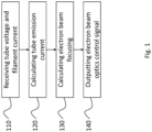
- a method according to embodiments of the invention is illustrated in Fig. 1 .
- the method aims to determine an X-ray tube emission current at a certain moment in time during a kVp switching cycle, such as e.g. at a time point during a rapid transition from high to low peak voltage or from low to high peak voltage during such a switching cycle.
- the time point may thus be a point in time when at least one of the tube voltage, filament current and/or emission current is in rapid transition.
- the time point may be at a time during a kVp switching cycle when all the three parameters are (temporarily) stable. The latter may occur during part of a kVp switching plateau.
- a tube voltage 11 and a filament current 12 corresponding to the specific time point of the kVp switching cycle are received.
- a tube emission current 13 is calculated 120 with an X-ray tube emission current model 310, based on the tube voltage 11 and the filament current 12.
- the X-ray tube emission current model 310 may comprise a look up table to match pairs of tube voltages and filament currents to emission currents.
- the emission current 13 has been calculated, the tube voltage 11, filament current 12 and emission current 13 corresponding to the specific time point are known.
- an electron beam focusing current and/or focusing voltage (depending on the type of beam optics used) 14 is calculated.
- an electron beam optics control signal 15 is output 140, based on the calculated electron beam focusing current and/or focusing voltage 14.
- the electron beam optics control signal 15 may thus be synchronized with the voltage transition.
- both the tube voltage and tube emission current may change very rapidly.
- the beam optics control signal 15 is kept constant or relatively constant during such a transition.
- Fig. 2 illustrates the method as described above with additional steps, according to embodiments of the invention.
- the method comprises receiving 210 one or multiple X-ray tube characteristics 21 at an earlier time point. I.e. in advance of the time point for which the emission current 13 is calculated 120 and for which the electron beam optics control signal 15 is output 140.
- an upcoming tube voltage 11 and/or an upcoming tube filament current 12 may be predicted 220 with a predictive X-ray tube model 410.
- Examples of X-ray tube characteristics may include a tube emission current, a tube voltage, a tube filament current, a tube capacitance, a high voltage generator capacitance, a high voltage cable capacitance, a tube age, an anode age, a temperature, a rotor speed, and/or a tube acoustic signal etc.
- the characteristic may be measured, e.g. in real-time, during a kVp switching cycle, or may be otherwise known or modeled.
- the prediction of the tube voltage 11 and/or filament current 12 may include the use of a look up table, such as but not limited to a 3-dimensional lookup table that maps emission currents to pairs of a tube voltage and a filament current.
- the predictive X-ray tube model 410 may be a physical model and/or a digital twin of the X-ray tube.
- Such an X-ray tube model may e.g. model the capacitances of the output side of the high voltage generator, the high voltage cable and/or the tube itself.
- the model may allow to compute e.g. the tube voltage slope based on input such as the energy provided by the high voltage generator.
- the predicted tube voltage 11 and/or filament current 12 may subsequently be used as input 110 to the X-ray tube emission current model 310 in order to calculate 120 a tube emission current 13 at the relevant (future) time point.
- the predicted tube voltage 11 and/or filament current 12 may subsequently be used as input 110 to the X-ray tube emission current model 310 in order to calculate 120 a tube emission current 13 at the relevant (future) time point.
- Fig. 3 illustrates a schematic process flow comparable to the method illustrated with an example in Fig. 1 .
- a tube voltage 11 and a filament current 12 are input to an emission current model 310.
- the tube voltage 11 and the filament current 12 correspond to a time point T1 in a kVp switching cycle.
- T1 may correspond to a time point for which a measurement of an emission current would be challenging or even impossible. Such as, but not limited to, during a rapid voltage transition from high to low or low to high peak voltage.
- the emission current model 310 calculates and outputs a calculated emission current 13 corresponding to the same time point T1.
- the emission current model 310 may apply a look up table and/or may include other processing to generate an emission current 13 output based on input including the tube voltage 11 and the filament current 12.
- the model 310 may include a machine learning algorithm, such as e.g. a neural network. When machine learning is implemented in the emission current model 310, such a model may be trained with known sets of tube voltages and filament currents corresponding to known, such as measured or modeled, emission currents.
- the calculated emission current 13 and the tube voltage 11, and optionally the filament current 12, are fed to a beam focusing calculator 320.
- the beam focusing calculator 320 may output a beam focusing current and/or voltage 14 suitable for the beam optics at time point T1.
- a beam optics controller Based on the calculated beam focusing current and/or voltage 14, a beam optics controller generates and outputs an electron beam optics control signal 15.
- FIG. 3 and Fig. 4 illustrates the process with several separate blocks
- the method according to embodiments of the invention may be carried out by a single or by multiple units. Such as, but not limited to, a single or distributed controller.
- Fig. 4 illustrates a schematic process flow of a method including a predictive X-ray tube model 410, according to embodiments of the invention. From left to right in the Fig, the flow starts with inputting at least one X-ray tube characteristic 21 to the predictive X-ray tube model 410 at a time point T0. In other words, at an earlier time point compared to T1. As mentioned above, in relation to Fig.
- examples of X-ray tube characteristics may include a tube emission current, a tube voltage, a tube filament current, a tube capacitance, a high voltage generator capacitance, a high voltage cable capacitance, a tube age, an anode age, a temperature, a rotor speed, and/or a tube acoustic signal.
- the characteristic may be measured, e.g. in real-time at T0, during a kVp switching cycle, or may be otherwise known at T0.
- the predictive model 410 generates as an output a predicted tube voltage 11 and/or filament current 12 at T 1.
- the prediction of the tube voltage 11 and/or filament current 12 may include the use of a look up table, such as but not limited to a 3-dimensional lookup table that maps emission currents to pairs of a tube voltage and a filament current.
- the predictive X-ray tube model 410 may be a physical model and/or a digital twin of the X-ray tube. Such an X-ray tube model may e.g. model the capacitances of the output side of the high voltage generator, the high voltage cable and/or the tube itself.
- the model 410 may allow to compute e.g. the tube voltage slope based on input such as the energy provided by the high voltage generator.
- the predictive X-ray tube model 410 may apply a machine learning algorithm, such as a neural network.
- the machine learning algorithm may be trained with training sets comprising known values of the tube characteristics and known, such as measured or modeled, tube voltages and/or filament currents.
- the predicted tube voltage 11 and/or filament current 12 at T1 is used as input to the emission current model 310, whereafter the process flow is comparable to that in Fig. 3 .
- the predictive X-ray tube model 410 predicts a tube voltage waveform over time, such as at time points T1, T2, T3 etc. With the predicted tube voltage waveform and, calculated or measured, filament currents at the same time points used as input to the emission current model 310, a subsequent emission current waveform for time points T1, T2, T3 etc. may be calculated.
- voltage waveforms and emission current waveforms covering multiple time points of a kVp switching cycle, may be predicted by the modeling. In this way it may be possible to timely compute and control a focusing currents or voltage waveform that minimizes size and position deviations of the focal spot during kVp switching.
- Fig. 5 schematically illustrates an X-ray system 500 according to embodiments of the invention.
- the X-ray system 500 may be a computed tomography system or another system for spectral imaging with X-ray kVp switching.
- the system 500 includes an X-ray tube 510 comprising an anode 530 and a cathode 520 with a filament.
- a filament current may be applied to the filament, such that the filament is heated and expels electrons via thermionic emission.
- a tube voltage may be applied across the cathode 520 and the anode 530 and cause a beam of the electrons to accelerate from the cathode 520 and impinge the anode 530, thereby generating X-rays.
- the spectrum of X-rays depends on the peak tube voltage (kVp) applied between the cathode 520 and the anode 530.
- the X-ray tube 510 comprises electron beam optics 540 configured to control a focal spot size and/or focal spot position of an electron beam impacting the anode 530.
- the electron beam optics 540 may be electrostatic electron beam optics configured to control the focal spot size and/or position with at least one electrode and/or magnetic beam focusing optics configured to control the focal spot size and/or position with at least one magnetic focusing coil.
- the X-ray system 500 comprises a controller 560.
- the controller may comprise or otherwise interact with a processor, such as but not limited to a computer, a computer network, and/or another programmable apparatus, such as a single and/or multi core processing unit, a graphics processing unit, an accelerated processing unit, a digital signal processor, a field programmable gate array, and/or an application-specific integrated circuit, etc.
- a processor such as but not limited to a computer, a computer network, and/or another programmable apparatus, such as a single and/or multi core processing unit, a graphics processing unit, an accelerated processing unit, a digital signal processor, a field programmable gate array, and/or an application-specific integrated circuit, etc.
- the controller 560 is configured to receive a tube voltage 11 and a filament current 12 corresponding to a first time point of an X-ray tube kVp switching cycle; calculating, with an X-ray tube emission current model 310, a tube emission current 13 at the first time point, wherein the calculation is based on the tube voltage 11 and the tube filament current 12; calculating an electron beam focusing current and/or focusing voltage 14 based on the calculated tube emission current 13 and the tube voltage 11; and outputting an electron beam optics control signal 15 based on the calculated electron beam focusing current and/or focusing voltage 14.
- the controller may also be configured to receive one or multiple X-ray tube characteristics 21 at a second time point, wherein the second time point is earlier than the first time point; and predicting, with a predictive X-ray tube model 410 and based on the X-ray tube characteristics 21, the tube voltage 11 at the first time point and/or the tube filament current 12 at the first time point, wherein the predicted tube voltage 11 and/or filament current 12 form input to the X-ray tube emission current model 310.
- the controller 560 may be comprised of one or multiple local and/or remote units and may be separate from or integrated with e.g. the high voltage generator 550.
- the X-ray system further comprises a power supply 570.
- the power supply 570 is configured to receive the electron beam optics control signal 15 from the controller 560 and apply the calculated electron beam focusing current and/or focusing voltage 14 to the electron beam optics 540 to control the focal spot size and/or focal spot position during kVp switching.
- the power supply 570 may be separate from or integrated with e.g. the high voltage generator 550. With the exemplified system it may be possible to timely control the electron beam optics during very rapid changes of the tube voltage and tube emission current. Such as e.g. during spectral CT with kVp switching.
Landscapes
- Health & Medical Sciences (AREA)
- General Health & Medical Sciences (AREA)
- Toxicology (AREA)
- X-Ray Techniques (AREA)
Priority Applications (5)
| Application Number | Priority Date | Filing Date | Title |
|---|---|---|---|
| EP22215748.9A EP4391729A1 (fr) | 2022-12-22 | 2022-12-22 | Commande d'optique de faisceau d'électrons de tube à rayons x pendant une commutation kvp |
| EP23821680.8A EP4640011A1 (fr) | 2022-12-22 | 2023-12-13 | Commande d'optique de faisceau d'électrons de tube à rayons x pendant une commutation kvp |
| PCT/EP2023/085491 WO2024132742A1 (fr) | 2022-12-22 | 2023-12-13 | Commande d'optique de faisceau d'électrons de tube à rayons x pendant une commutation kvp |
| CN202380087894.XA CN120419288A (zh) | 2022-12-22 | 2023-12-13 | 在kvp切换期间控制x射线管电子束光学器件 |
| US19/140,130 US20260046993A1 (en) | 2022-12-22 | 2023-12-13 | Controlling x-ray tube electron beam optics during kvp switching |
Applications Claiming Priority (1)
| Application Number | Priority Date | Filing Date | Title |
|---|---|---|---|
| EP22215748.9A EP4391729A1 (fr) | 2022-12-22 | 2022-12-22 | Commande d'optique de faisceau d'électrons de tube à rayons x pendant une commutation kvp |
Publications (1)
| Publication Number | Publication Date |
|---|---|
| EP4391729A1 true EP4391729A1 (fr) | 2024-06-26 |
Family
ID=84569434
Family Applications (2)
| Application Number | Title | Priority Date | Filing Date |
|---|---|---|---|
| EP22215748.9A Withdrawn EP4391729A1 (fr) | 2022-12-22 | 2022-12-22 | Commande d'optique de faisceau d'électrons de tube à rayons x pendant une commutation kvp |
| EP23821680.8A Pending EP4640011A1 (fr) | 2022-12-22 | 2023-12-13 | Commande d'optique de faisceau d'électrons de tube à rayons x pendant une commutation kvp |
Family Applications After (1)
| Application Number | Title | Priority Date | Filing Date |
|---|---|---|---|
| EP23821680.8A Pending EP4640011A1 (fr) | 2022-12-22 | 2023-12-13 | Commande d'optique de faisceau d'électrons de tube à rayons x pendant une commutation kvp |
Country Status (4)
| Country | Link |
|---|---|
| US (1) | US20260046993A1 (fr) |
| EP (2) | EP4391729A1 (fr) |
| CN (1) | CN120419288A (fr) |
| WO (1) | WO2024132742A1 (fr) |
Citations (3)
| Publication number | Priority date | Publication date | Assignee | Title |
|---|---|---|---|---|
| US20180228011A1 (en) * | 2017-02-06 | 2018-08-09 | Canon Medical Systems Corporation | X-ray computed tomography apparatus |
| EP3528274A1 (fr) * | 2018-02-19 | 2019-08-21 | Koninklijke Philips N.V. | Source des rayons x et dispositif de l'imagerie utilisant des rayons x |
| JP2022015134A (ja) * | 2020-07-08 | 2022-01-21 | キヤノンメディカルシステムズ株式会社 | X線コンピュータ断層撮影装置及びx線診断装置 |
-
2022
- 2022-12-22 EP EP22215748.9A patent/EP4391729A1/fr not_active Withdrawn
-
2023
- 2023-12-13 WO PCT/EP2023/085491 patent/WO2024132742A1/fr not_active Ceased
- 2023-12-13 CN CN202380087894.XA patent/CN120419288A/zh active Pending
- 2023-12-13 US US19/140,130 patent/US20260046993A1/en active Pending
- 2023-12-13 EP EP23821680.8A patent/EP4640011A1/fr active Pending
Patent Citations (3)
| Publication number | Priority date | Publication date | Assignee | Title |
|---|---|---|---|---|
| US20180228011A1 (en) * | 2017-02-06 | 2018-08-09 | Canon Medical Systems Corporation | X-ray computed tomography apparatus |
| EP3528274A1 (fr) * | 2018-02-19 | 2019-08-21 | Koninklijke Philips N.V. | Source des rayons x et dispositif de l'imagerie utilisant des rayons x |
| JP2022015134A (ja) * | 2020-07-08 | 2022-01-21 | キヤノンメディカルシステムズ株式会社 | X線コンピュータ断層撮影装置及びx線診断装置 |
Also Published As
| Publication number | Publication date |
|---|---|
| CN120419288A (zh) | 2025-08-01 |
| EP4640011A1 (fr) | 2025-10-29 |
| US20260046993A1 (en) | 2026-02-12 |
| WO2024132742A1 (fr) | 2024-06-27 |
Similar Documents
| Publication | Publication Date | Title |
|---|---|---|
| US10405813B2 (en) | Panoramic imaging using multi-spectral X-ray source | |
| JP6759207B2 (ja) | 静態リアルタイムct画像形成システム及びその画像形成制御方法 | |
| EP3294044B1 (fr) | Tube à rayons x avec électrode de maillage | |
| US20060109951A1 (en) | X-ray tomography apparatus and operating method for generating multiple energy images | |
| US7409043B2 (en) | Method and apparatus to control radiation tube focal spot size | |
| JP7114525B2 (ja) | 異なるエネルギーレベルおよび焦点スポット位置で撮像するように構成されたコンピュータ断層撮影システムおよび方法 | |
| US11116462B2 (en) | X-ray system and method for generating x-ray image in color | |
| US10660190B2 (en) | X-ray computed tomography apparatus | |
| CN107072022B (zh) | X射线断层扫描方法及系统 | |
| US9952164B2 (en) | Photon-counting CT-system with reduced detector counting-rate requirements | |
| JP2015116408A (ja) | X線ct装置及び不良素子補正方法 | |
| CN113841044B (zh) | 在kVp切换谱(多能量)成像扫描期间维持给定焦斑尺寸 | |
| EP4391729A1 (fr) | Commande d'optique de faisceau d'électrons de tube à rayons x pendant une commutation kvp | |
| JP7086622B2 (ja) | X線コンピュータ断層撮影装置 | |
| US4464775A (en) | Method and apparatus for collecting X-ray absorption data in X-ray computed tomography apparatus | |
| CN104586420A (zh) | 一种ct低剂量扫描方法、设备及系统 | |
| JP6377370B2 (ja) | X線管球装置及びx線ct装置 | |
| EP4635261B1 (fr) | Détermination du courant d'un tube à rayons x | |
| EP3860463B1 (fr) | Système pour fournir une image spectrale | |
| EP4344359A1 (fr) | Imagerie avec commutation kvp | |
| EP4567856A1 (fr) | Point focal de faisceau d'électrons | |
| EP4611004A1 (fr) | Surveillance d'un point focal |
Legal Events
| Date | Code | Title | Description |
|---|---|---|---|
| PUAI | Public reference made under article 153(3) epc to a published international application that has entered the european phase |
Free format text: ORIGINAL CODE: 0009012 |
|
| STAA | Information on the status of an ep patent application or granted ep patent |
Free format text: STATUS: THE APPLICATION HAS BEEN PUBLISHED |
|
| AK | Designated contracting states |
Kind code of ref document: A1 Designated state(s): AL AT BE BG CH CY CZ DE DK EE ES FI FR GB GR HR HU IE IS IT LI LT LU LV MC ME MK MT NL NO PL PT RO RS SE SI SK SM TR |
|
| STAA | Information on the status of an ep patent application or granted ep patent |
Free format text: STATUS: THE APPLICATION IS DEEMED TO BE WITHDRAWN |
|
| 18D | Application deemed to be withdrawn |
Effective date: 20250103 |