EP4344523B1 - Dispositif de commande d'un relevage hydraulique à trois points - Google Patents
Dispositif de commande d'un relevage hydraulique à trois points Download PDFInfo
- Publication number
- EP4344523B1 EP4344523B1 EP23196759.7A EP23196759A EP4344523B1 EP 4344523 B1 EP4344523 B1 EP 4344523B1 EP 23196759 A EP23196759 A EP 23196759A EP 4344523 B1 EP4344523 B1 EP 4344523B1
- Authority
- EP
- European Patent Office
- Prior art keywords
- valve
- pressure
- hydraulic
- way
- outlet
- Prior art date
- Legal status (The legal status is an assumption and is not a legal conclusion. Google has not performed a legal analysis and makes no representation as to the accuracy of the status listed.)
- Active
Links
Images


Classifications
-
- A—HUMAN NECESSITIES
- A01—AGRICULTURE; FORESTRY; ANIMAL HUSBANDRY; HUNTING; TRAPPING; FISHING
- A01B—SOIL WORKING IN AGRICULTURE OR FORESTRY; PARTS, DETAILS, OR ACCESSORIES OF AGRICULTURAL MACHINES OR IMPLEMENTS, IN GENERAL
- A01B59/00—Devices specially adapted for connection between animals or tractors and agricultural machines or implements
- A01B59/06—Devices specially adapted for connection between animals or tractors and agricultural machines or implements for machines mounted on tractors
- A01B59/066—Devices specially adapted for connection between animals or tractors and agricultural machines or implements for machines mounted on tractors of the type comprising at least two lower arms and one upper arm generally arranged in a triangle, e.g. three-point hitches
-
- A—HUMAN NECESSITIES
- A01—AGRICULTURE; FORESTRY; ANIMAL HUSBANDRY; HUNTING; TRAPPING; FISHING
- A01B—SOIL WORKING IN AGRICULTURE OR FORESTRY; PARTS, DETAILS, OR ACCESSORIES OF AGRICULTURAL MACHINES OR IMPLEMENTS, IN GENERAL
- A01B63/00—Lifting or adjusting devices or arrangements for agricultural machines or implements
- A01B63/02—Lifting or adjusting devices or arrangements for agricultural machines or implements for implements mounted on tractors
- A01B63/10—Lifting or adjusting devices or arrangements for agricultural machines or implements for implements mounted on tractors operated by hydraulic or pneumatic means
- A01B63/1006—Lifting or adjusting devices or arrangements for agricultural machines or implements for implements mounted on tractors operated by hydraulic or pneumatic means the hydraulic or pneumatic means structurally belonging to the tractor
Definitions
- the invention relates to an arrangement for controlling a hydraulic three-point linkage, comprising a hydraulic cylinder with a working chamber which can be pressurised with hydraulic fluid to change the lifting position of a lower link included in the hydraulic three-point linkage, and first and second seat valves communicating with the working chamber, the first seat valve being designed to establish an inlet connection with a high-pressure source and the second seat valve being designed to establish a return connection with a hydraulic reservoir.
- the hydraulic cylinder is actuated by an electrically controllable valve arrangement, which comprises a first seat valve supplied with hydraulic fluid from a high-pressure pump for pressurizing a working chamber of the hydraulic cylinder, and a second seat valve for relieving pressure from the working chamber, with the second seat valve opening into a hydraulic reservoir.
- the first seat valve is used to raise, and the second seat valve to lower the lower link of the three-point linkage.
- Such an arrangement is known, for example, from EP 0 348 854 A1 known.
- the known valve arrangement has the property that the volume flow of the hydraulic fluid passing through the seat valves and thus the travel speed of the hydraulic cylinder depends both on the system pressure of the high-pressure pump and on the current working pressure within the piston chamber of the hydraulic cylinder.
- the arrangement for controlling a hydraulic three-point linkage comprises a hydraulic cylinder with a working chamber that can be pressurized with hydraulic fluid to change the lifting position of a lower link included in the hydraulic three-point linkage, as well as first and second seat valves communicating with the working chamber, the first seat valve being designed to establish an inlet connection with a high-pressure source and the second seat valve being designed to establish a return connection with a hydraulic reservoir.
- a pressure compensation valve is connected upstream of each of the two seat valves with respect to its respective flow direction. This ensures that the volume flow of hydraulic fluid passing through the seat valves, and thus the travel speed of the hydraulic cylinder, remains essentially constant and depends exclusively on the current actuation state of the respective seat valve.
- the pressure compensation valve is formed, in particular, by a pressure control valve that compares the hydraulic pressure applied to the seat valve outlet side with the hydraulic pressure applied to the seat valve inlet side and adjusts it to a fixed differential pressure.
- the pressure compensation valve and seat valve can be integrated into a common valve assembly.
- an electric motor-driven eccentric disc can be provided, by means of which one or the other of the two seat valves can be against a restoring spring force into an open position.
- Such a structure is EP 0 348 854 A1 described.
- Fig. 1 shows a schematically illustrated embodiment of the arrangement 10 according to the invention for controlling a hydraulic three-point linkage 12.
- the hydraulic lifting mechanism 14 has left and right hydraulic cylinders 16, by means of which left and right lever arms, which are connected to one another in a rotationally fixed manner via a rigid shaft, can be pivoted, to the free ends of which the two lower links are in turn articulated via respective lifting struts.
- Fig. 1 only one of the two hydraulic cylinders 16 is shown, each of which has a first working chamber 18 (so-called lifting chamber) which is used to change the lifting position of the lower links can be pressurized with hydraulic fluid.
- first working chamber 18 so-called lifting chamber
- the hydraulic cylinders 16 are actuated by an electrically controllable valve arrangement 20, which has a first seat valve 24, supplied with hydraulic fluid from a high-pressure source 22 of the agricultural tractor, for pressurizing the first working chambers 18, which are connected in parallel hydraulically, and a second seat valve 26, provided for relieving pressure from the first working chambers 18.
- the second seat valve 26 opens into a hydraulic reservoir 28.
- the first seat valve 24, which communicates with the first working chambers 18, serves to raise the lower links of the three-point linkage 12 by establishing an inlet connection 30 with the high-pressure source 22, while the second seat valve 26, which communicates with the first working chambers 18, serves to lower the lower links of the three-point linkage 12 by establishing a return connection 32 with the hydraulic reservoir 28.
- a pressure relief valve 38 By means of which the two seat valves 24, 26 move towards the hydraulic reservoir 28 can be bridged. If a pressure threshold value, typically in the range of 230 to 250 bar, is exceeded, the pressure relief valve 38 diverts the hydraulic fluid in the piston chambers 18 toward the hydraulic reservoir 28 until the pressure falls below the threshold value. Furthermore, a one-way valve 40 is provided, which is located in the inlet connection 30 between the first seat valve 24 and the first working chambers 18 of the hydraulic cylinders 16. The one-way valve 40 prevents the lower links from suddenly dropping when the first seat valve 24 opens due to a pressure deficit on the side of the high-pressure source 22.
- an electric motor-driven eccentric disc 42 is provided, by means of which one or the other of the two seat valves 24, 26 can be pushed into an open position against a restoring spring force.
- a pressure compensation valve 48, 50 is connected upstream of each of the two seat valves 24, 26 with respect to its respective flow direction 44, 46. In this way, it is ensured that the volume flow of the hydraulic fluid passing through the seat valves 24, 26 and thus the travel speed of the hydraulic cylinders 16 remains essentially constant and depends exclusively on the current actuation state of the respective seat valve 24, 26.
- each of the pressure compensation valves 48, 50 is formed by a pressure control valve 52, 54, which compares a hydraulic pressure applied to the respective seat valve 24, 26 on the outlet side with a hydraulic pressure applied to the inlet side and adjusts it to a fixed differential pressure.
- the pressure compensation valve 48, 50 and the seat valve 24, 26 can be integrated into a common valve assembly.
- these are double-acting hydraulic cylinders 16 with respective second working chambers 56 (so-called pressure chambers), which are hydraulically connected in parallel to a control valve arrangement 58, by means of which a predetermined target pressure can be set in the second working chambers 56.
- a predetermined target pressure By appropriately specifying the target pressure, it is possible to exert a downward force on the two lower links using the hydraulic cylinders 16 if the second seat valve 26 is in its open position. This allows, in certain agricultural applications, such as cultivating or plowing, the contact pressure exerted by the implement to be specifically increased if the weight of the implement alone is not sufficient to achieve the desired soil cultivation result.
- an additional 3/2-way main valve 70 is provided, which has a further outlet 72 communicating with the second working chambers 56 of the hydraulic cylinders 16, wherein by means of the control pressure provided by the 3/2-way pilot valve 60, the 3/2-way main valve 70 can be pushed via a first control inlet 74 into a first position 76a connecting the further outlet 72 to the high-pressure source 22 and by returning the working pressure generated in the second working chambers 56 via a second control inlet 78 in the opposite valve actuation direction into a second position 76b connecting the further outlet 72 to the hydraulic reservoir 28.
- the 3/2-way pilot valve 60 equipped with the electric actuator 64, serves only to pilot the 3/2-way main valve 70, so that no special requirements are placed on the former with regard to the flow rates to be achieved.
- the 3/2-way pilot valve 60 is therefore comparatively compact and cost-effective.
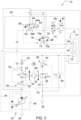
- the variants differ only in the type of pressure feedback to the control input 68 of the 3/2-way pilot valve 60. Accordingly, Fig. 2 which is connected to outlet 62 of the 3/2-way pilot valve 60 applied control pressure is fed back directly to its control input 68, whereas according to Fig. 3 a return of the working pressure actually generated in the second working chambers 56 takes place.
- a contact pressure control is implemented on the agricultural tractor 10.
- the control valve arrangement 58 comprises an electrically switchable 4/2-way valve 80, by means of which the outlet 62 of the 3/2-way pilot valve 60 can be connected to the first working chambers 18 of the hydraulic cylinders 16 instead of to the first control inlet 74 of the 3/2-way main valve 70, and at the same time the first control inlet 74 of the 3/2-way main valve 70 can be connected to the hydraulic reservoir 28 instead of to the outlet 62 of the 3/2-way pilot valve 60.
- the check valve 82 ensures that the connection between the second working chambers 56 of the hydraulic cylinders 16 and the hydraulic reservoir 28 is interrupted if the contact pressure control is not active, which is the case here when the 4/2-way valve 80 is in its unactuated basic position.
- the check valve 82 assumes its open position as soon as a connection to the outlet 62 of the 3/2-way pilot valve 60 is established via the 4/2-way valve 80 and a certain minimum pressure is reached there, which is typically 5 to 10 bar.
- FIG. 2 The first embodiment shown provides for the outlet 62 of the 3/2-way pilot valve 60 to be connected directly to the check valve 82.
- the 4/2-way valve 80 serves exclusively to actuate the check valve 82.
- the outlet 62 of the 3/2-way pilot valve 60 is also connected to the shut-off valve 82 via the 4/2-way valve 80.
- the first embodiment results in lower pressure losses than the second and also allows a more compact design of the 4/2-way valve 80.
- the above description is to be understood merely as an example, in that both embodiments can be used equally well in conjunction with the first and second variants of the control valve arrangement 58.
- this arrangement can also be used universally as a single-acting hydraulic cylinder or as a double-acting hydraulic cylinder, the second working chamber of which communicates freely with the hydraulic reservoir 28.
- the control valve arrangement 58 is non-functional and therefore not present.
Landscapes
- Life Sciences & Earth Sciences (AREA)
- Engineering & Computer Science (AREA)
- Mechanical Engineering (AREA)
- Soil Sciences (AREA)
- Environmental Sciences (AREA)
- Zoology (AREA)
- Lifting Devices For Agricultural Implements (AREA)
- Fluid-Pressure Circuits (AREA)
Claims (8)
- Agencement de commande d'un attelage hydraulique trois points, comprenant un vérin hydraulique (16) avec une chambre de travail (18) qui est apte à être alimentée en fluide hydraulique sous pression pour modifier la position de levage d'un bras inférieur entouré par l'attelage hydraulique trois points (12), ainsi que des première et deuxième vannes à siège (24, 26) communiquant avec la chambre de travail (18), la première vanne à siège (24) étant conçue de manière à établir une liaison d'alimentation (30) avec une source haute pression (22) et la deuxième vanne à siège (26) étant conçue de manière à établir une liaison de retour (32) avec un réservoir hydraulique (28), caractérisé en ce qu'une vanne de compensation de pression (48, 50) est montée en amont de chacune des deux vannes à siège (24, 26) par rapport à son sens d'écoulement respectif (44, 46).
- Agencement selon la revendication 1, caractérisé en ce qu'il s'agit d'un vérin hydraulique à simple effet ou d'un vérin hydraulique à double effet avec une chambre de travail supplémentaire qui communique librement avec le réservoir hydraulique (28).
- Agencement selon la revendication 1, caractérisé en ce qu'il s'agit d'un vérin hydraulique à double effet (16) avec une chambre de travail supplémentaire (56) qui est reliée à un agencement (58) de vanne de commande au moyen duquel une pression cible prédéfinie est apte à être réglée dans la chambre de travail supplémentaire (56) .
- Agencement selon la revendication 3, caractérisé en ce que l'agencement (58) de vanne de commande comprend une vanne pilote à 3/2 voies (60) avec une sortie (62) pour fournir une pression de commande correspondant à la pression cible prédéterminée, la vanne pilote à 3/2 voies (60) étant actionnée par un actionneur électrique (64) pour fournir la pression de commande correspondant à la pression cible prédéfinie, dans une première position (66a) reliant la sortie (62) à la source haute pression (22) et, par le retour de la pression de commande ou de la pression de travail générée dans l'autre chambre de travail (56) via une entrée de commande (68) dans le sens opposé à l'actionnement de la vanne dans une deuxième position (66b) reliant la sortie (62) au réservoir hydraulique (28).
- Agencement selon la revendication 4, caractérisé en ce que la pression de commande fournie à la sortie (62) de la vanne pilote à 3/2 voies (60) sert à alimenter directement en pression l'autre chambre de travail (56) du vérin hydraulique (16).
- Agencement selon la revendication 4, caractérisé en ce qu'il est prévu une vanne principale à 3/2 voies (70) qui présente une sortie supplémentaire (72) communiquant avec l'autre chambre de travail (56) du vérin hydraulique (16), la pression de commande fournie par la vanne pilote 3/2 voies (60) permettant de placer la vanne principale 3/2 voies (70) dans une première position (76a) reliant la sortie supplémentaire (72) à la source haute pression (22) via une première entrée de commande (74) et, par le retour de la pression de travail générée dans l'autre chambre de travail (56) par l'intermédiaire d'une deuxième entrée de commande (78) dans le sens inverse de l'actionnement de la vanne, dans une deuxième position (76b) reliant la sortie supplémentaire (72) au réservoir hydraulique (28).
- Agencement selon la revendication 6, caractérisé en ce que l'agencement (58) de vanne de commande comprend une vanne à 4/2 voies (80), au moyen de laquelle la sortie (62) de la vanne pilote à 3/2 voies (60) est apte à être reliée à la chambre de travail (18) du vérin hydraulique (16) au lieu de la première entrée de commande (74) de la vanne principale à 3/2 voies (70), et la première entrée de commande (74) de la vanne principale à 3/2 voies (70) est apte à être reliée au réservoir hydraulique (28) au lieu de la sortie (62) de la vanne pilote à 3/2 voies (60).
- Tracteur agricole avec un dispositif d'attelage à trois points (12) ainsi qu'avec un agencement (10) pour commander le dispositif hydraulique d'attelage à trois points (12) selon au moins l'une des revendications précédentes.
Applications Claiming Priority (1)
| Application Number | Priority Date | Filing Date | Title |
|---|---|---|---|
| DE102022124969.7A DE102022124969A1 (de) | 2022-09-28 | 2022-09-28 | Anordnung zur Steuerung eines hydraulischen Dreipunkt- Krafthebers |
Publications (2)
| Publication Number | Publication Date |
|---|---|
| EP4344523A1 EP4344523A1 (fr) | 2024-04-03 |
| EP4344523B1 true EP4344523B1 (fr) | 2025-07-02 |
Family
ID=88017751
Family Applications (1)
| Application Number | Title | Priority Date | Filing Date |
|---|---|---|---|
| EP23196759.7A Active EP4344523B1 (fr) | 2022-09-28 | 2023-09-12 | Dispositif de commande d'un relevage hydraulique à trois points |
Country Status (2)
| Country | Link |
|---|---|
| EP (1) | EP4344523B1 (fr) |
| DE (1) | DE102022124969A1 (fr) |
Citations (14)
| Publication number | Priority date | Publication date | Assignee | Title |
|---|---|---|---|---|
| US3423935A (en) | 1966-12-30 | 1969-01-28 | Weatherhead Co | Hydraulic control system for tractor drawn implement |
| EP0348854A2 (fr) | 1988-06-28 | 1990-01-03 | Deere & Company | Dispositif de commande pour au moins un clapet |
| US5868059A (en) | 1997-05-28 | 1999-02-09 | Caterpillar Inc. | Electrohydraulic valve arrangement |
| US6745992B2 (en) | 2002-08-05 | 2004-06-08 | Husco International, Inc. | Pilot operated control valve having a poppet with integral pressure compensating mechanism |
| EP1496009A1 (fr) | 2003-07-05 | 2005-01-12 | Deere & Company | Suspension hydraulique |
| US20060266210A1 (en) | 2005-05-31 | 2006-11-30 | Caterpillar Inc. And Shin Caterpillar Mitsubishi Ltd. | Hydraulic system having a post-pressure compensator |
| US20070277519A1 (en) | 2004-07-09 | 2007-12-06 | Soenke Jessen | Lifting Gear Valve Arrangement |
| US20080295681A1 (en) | 2007-05-31 | 2008-12-04 | Caterpillar Inc. | Hydraulic system having an external pressure compensator |
| US8925439B2 (en) | 2011-01-13 | 2015-01-06 | Husco International, Inc. | Valve control valve circuit for operating a single acting hydraulic cylinder |
| EP2884118A1 (fr) | 2013-10-30 | 2015-06-17 | AGCO International GmbH | Système d'alimentation hydraulique |
| EP3321515A1 (fr) | 2016-11-09 | 2018-05-16 | AGCO International GmbH | Système d'alimentation de cylindre hydraulique |
| US20180209450A1 (en) | 2015-07-24 | 2018-07-26 | Log Hydraulik Gmbh | Hydraulic upper link |
| DE102017219942A1 (de) | 2017-11-09 | 2019-05-09 | Robert Bosch Gmbh | Ventilanordung für Hubwerkssteuerung mit einer Druckregelvorrichtung |
| CN111802010A (zh) | 2020-07-22 | 2020-10-23 | 河南科技大学 | 一种液压泵后置式拖拉机电液悬挂系统 |
-
2022
- 2022-09-28 DE DE102022124969.7A patent/DE102022124969A1/de active Pending
-
2023
- 2023-09-12 EP EP23196759.7A patent/EP4344523B1/fr active Active
Patent Citations (14)
| Publication number | Priority date | Publication date | Assignee | Title |
|---|---|---|---|---|
| US3423935A (en) | 1966-12-30 | 1969-01-28 | Weatherhead Co | Hydraulic control system for tractor drawn implement |
| EP0348854A2 (fr) | 1988-06-28 | 1990-01-03 | Deere & Company | Dispositif de commande pour au moins un clapet |
| US5868059A (en) | 1997-05-28 | 1999-02-09 | Caterpillar Inc. | Electrohydraulic valve arrangement |
| US6745992B2 (en) | 2002-08-05 | 2004-06-08 | Husco International, Inc. | Pilot operated control valve having a poppet with integral pressure compensating mechanism |
| EP1496009A1 (fr) | 2003-07-05 | 2005-01-12 | Deere & Company | Suspension hydraulique |
| US20070277519A1 (en) | 2004-07-09 | 2007-12-06 | Soenke Jessen | Lifting Gear Valve Arrangement |
| US20060266210A1 (en) | 2005-05-31 | 2006-11-30 | Caterpillar Inc. And Shin Caterpillar Mitsubishi Ltd. | Hydraulic system having a post-pressure compensator |
| US20080295681A1 (en) | 2007-05-31 | 2008-12-04 | Caterpillar Inc. | Hydraulic system having an external pressure compensator |
| US8925439B2 (en) | 2011-01-13 | 2015-01-06 | Husco International, Inc. | Valve control valve circuit for operating a single acting hydraulic cylinder |
| EP2884118A1 (fr) | 2013-10-30 | 2015-06-17 | AGCO International GmbH | Système d'alimentation hydraulique |
| US20180209450A1 (en) | 2015-07-24 | 2018-07-26 | Log Hydraulik Gmbh | Hydraulic upper link |
| EP3321515A1 (fr) | 2016-11-09 | 2018-05-16 | AGCO International GmbH | Système d'alimentation de cylindre hydraulique |
| DE102017219942A1 (de) | 2017-11-09 | 2019-05-09 | Robert Bosch Gmbh | Ventilanordung für Hubwerkssteuerung mit einer Druckregelvorrichtung |
| CN111802010A (zh) | 2020-07-22 | 2020-10-23 | 河南科技大学 | 一种液压泵后置式拖拉机电液悬挂系统 |
Non-Patent Citations (16)
| Title |
|---|
| "Fundamentals of Tractor Design", 7 November 2019, SPRINGER, ISBN: 978-3-030-32803-0, article KARL THEODOR RENIUS: "7 Tractor and implement", pages: 217 - 260, XP009566270, DOI: 10.1007/978-3-030-32804-7_7 |
| "Hydraulics in Tractors", 1 June 2014, BOSCH REXROTH AG, ISBN: 978-3-9814879-9-2, article HESSE, HORST: "10 Suspension systems", pages: 137 - 146, XP009566267 |
| "Hydraulics in Tractors", 1 June 2014, BOSCH REXROTH AG, ISBN: 978-3-9814879-9-2, article HESSE, HORST: "5 Directional and priority valves", pages: 37 - 67, XP009566266 |
| "Reference Book "Hydraulics in Tractors"", June 2014, BOSCH REXROTH AG, ISBN: 978-3-9814879-9-2, article "11 Electrohydraulic Hitch Control EHC", pages: 147 - 159 |
| ANONYMOUS: "Book 2, Chapter 10: Flow Control Circuits", PNEUMATIC VALVES, POWER&MOTION TECH, 18 December 2008 (2008-12-18), pages 1 - 33, XP009566274, Retrieved from the Internet <URL:https://www.powermotiontech.com/pneumatics/pneumatic-valves/article/21884324/book-2-chapter-10-flow-control-circuits> |
| ANONYMOUS: "Proportional Directional Valves. Series LCV (Reference: 100-P-000161-EN-04)", BROCHURE DIRECTIONAL VALVE LCV, BUCHER HYDRAULICS, 1 January 2022 (2022-01-01), pages 1 - 25, XP009566272, Retrieved from the Internet <URL:https://www.bucherhydraulics.com/datacat/files/Katalog/Ventile/Zwischenplattenventile_Sandwichventile/LCV/LCV_100-P-000161-en.pdf> |
| BOSCH REXROTH DRIVE AND CONTROL ACADEMY: "Drive & Control Training; Hydraulic Training; Load Sensing systems", July 2012 |
| BUD TRINKEL: "Book 2, Chapter 8: Directional Control Valves", EMERGING TECHNOLOGIES, POWER&MOTION TECH, 23 September 2008 (2008-09-23), pages 1 - 31, XP009566273, Retrieved from the Internet <URL:https://www.powermotiontech.com/technologies/other-technologies/article/21884325/book-2-chapter-8-directional-control-valves> |
| D18 - Statement of Gabriel Reitemann |
| D19 - GB1: Schematic of Hydraulic System for H2-18P/Fendt 930-942 Vario Gen 6 Tractors |
| D20 - GB2: An extract from a "Electrical diagrams and schematics" Workshop Service Manual for the 930-942 Vario Gen 6 series tractors dated September 2019 |
| D21 - GB3 An extract from Fendt 930-942 Vario Gen 6 Workshop Service Manual. Dated May 2021 |
| D22 - GB4 An extract from Fendt 930-942 Vario Gen 6 Tractors Operator’s Manual. Dated November 2020 |
| D23 - GB5 AGCO internal database screenshots relating to production of the 930-942 Vario Gen 6 series. |
| D24 - Extract from "Workshop Service Manual Fendt 900 Vario SCR" dated June 2015. Pages 1 to 4 and Section 8610 – "Electrohydraulic EPC control". |
| STEVE SKINNER: "A guide to selecting the right hydraulic flow control valve to optimise system performance and efficiency", WEBTEC, 1 November 2016 (2016-11-01), pages 1 - 10, XP009566275, Retrieved from the Internet <URL:https://files.webtec.com/FLOWVAL-ED-ENG-3543.pdf> |
Also Published As
| Publication number | Publication date |
|---|---|
| EP4344523A1 (fr) | 2024-04-03 |
| DE102022124969A1 (de) | 2024-03-28 |
Similar Documents
| Publication | Publication Date | Title |
|---|---|---|
| EP2043422B1 (fr) | Installation hydraulique | |
| WO2009049962A1 (fr) | Dispositif de levage hydraulique | |
| EP2269432A1 (fr) | Véhicule agricole | |
| EP1672225B1 (fr) | Assemblage de vannes et méthode de contrôle d'un consommateur hydraulique à double effet | |
| DE1582161B2 (de) | Hydraulische hubeinrichtung an maehdreschern | |
| EP2449267A2 (fr) | Dispositif de soupape | |
| EP0201046A2 (fr) | Outil de travail, en particulier outil de travail du sol | |
| DE3438353C2 (fr) | ||
| EP4344523B1 (fr) | Dispositif de commande d'un relevage hydraulique à trois points | |
| DE10310314B4 (de) | Antriebsanordnung, insbesondere Hebevorrichtung eines Arbeitsfahrzeugs | |
| EP3242543B1 (fr) | Engin agricole à châssis de roulement supplémentaire | |
| EP4344520B1 (fr) | Dispositif de commande d'un relevage hydraulique à trois points | |
| DE102006004423B4 (de) | Ventilanordnung zur Ansteuerung eines Hubwerkes oder Anbaugerätes sowie Verfahren zur Ansteuerung dieser | |
| EP0610900A1 (fr) | Circuit hydraulique pour accessoire flottant d'outil porté | |
| EP4275465B1 (fr) | Dispositif de réglage hydraulique | |
| DE19548943B4 (de) | Ventilanordnung | |
| EP3942909B1 (fr) | Charrue réversible portée | |
| DE69003414T2 (de) | Hydraulischer Kreis zum Gebrauch in Hebemechanismen bei Arbeitsfahrzeugen. | |
| AT501973B1 (de) | Landmaschine | |
| DE102024102511A1 (de) | Doppelt wirkende kupplungs-hydraulikventilanordnung | |
| EP4093176B1 (fr) | Engin agricole et son procédé de fonctionnement | |
| EP4388837B1 (fr) | Appareil de traitement du sol et procédé de fonctionnement d'un appareil de traitement du sol | |
| DE102006002066B4 (de) | Landmaschine | |
| DE102008057716A1 (de) | Landmaschine | |
| EP4310343A1 (fr) | Alimentation hydraulique commandée en charge pour un outil monté sur un tracteur agricole |
Legal Events
| Date | Code | Title | Description |
|---|---|---|---|
| PUAI | Public reference made under article 153(3) epc to a published international application that has entered the european phase |
Free format text: ORIGINAL CODE: 0009012 |
|
| STAA | Information on the status of an ep patent application or granted ep patent |
Free format text: STATUS: THE APPLICATION HAS BEEN PUBLISHED |
|
| AK | Designated contracting states |
Kind code of ref document: A1 Designated state(s): AL AT BE BG CH CY CZ DE DK EE ES FI FR GB GR HR HU IE IS IT LI LT LU LV MC ME MK MT NL NO PL PT RO RS SE SI SK SM TR |
|
| STAA | Information on the status of an ep patent application or granted ep patent |
Free format text: STATUS: REQUEST FOR EXAMINATION WAS MADE |
|
| 17P | Request for examination filed |
Effective date: 20241004 |
|
| RBV | Designated contracting states (corrected) |
Designated state(s): AL AT BE BG CH CY CZ DE DK EE ES FI FR GB GR HR HU IE IS IT LI LT LU LV MC ME MK MT NL NO PL PT RO RS SE SI SK SM TR |
|
| GRAP | Despatch of communication of intention to grant a patent |
Free format text: ORIGINAL CODE: EPIDOSNIGR1 |
|
| STAA | Information on the status of an ep patent application or granted ep patent |
Free format text: STATUS: GRANT OF PATENT IS INTENDED |
|
| INTG | Intention to grant announced |
Effective date: 20250212 |
|
| GRAS | Grant fee paid |
Free format text: ORIGINAL CODE: EPIDOSNIGR3 |
|
| GRAA | (expected) grant |
Free format text: ORIGINAL CODE: 0009210 |
|
| STAA | Information on the status of an ep patent application or granted ep patent |
Free format text: STATUS: THE PATENT HAS BEEN GRANTED |
|
| AK | Designated contracting states |
Kind code of ref document: B1 Designated state(s): AL AT BE BG CH CY CZ DE DK EE ES FI FR GB GR HR HU IE IS IT LI LT LU LV MC ME MK MT NL NO PL PT RO RS SE SI SK SM TR |
|
| REG | Reference to a national code |
Ref country code: GB Ref legal event code: FG4D Free format text: NOT ENGLISH |
|
| REG | Reference to a national code |
Ref country code: CH Ref legal event code: EP |
|
| REG | Reference to a national code |
Ref country code: DE Ref legal event code: R096 Ref document number: 502023001270 Country of ref document: DE |
|
| REG | Reference to a national code |
Ref country code: IE Ref legal event code: FG4D Free format text: LANGUAGE OF EP DOCUMENT: GERMAN |
|
| PGFP | Annual fee paid to national office [announced via postgrant information from national office to epo] |
Ref country code: DE Payment date: 20250820 Year of fee payment: 3 |
|
| PGFP | Annual fee paid to national office [announced via postgrant information from national office to epo] |
Ref country code: AT Payment date: 20251020 Year of fee payment: 3 Ref country code: FR Payment date: 20250925 Year of fee payment: 3 |
|
| REG | Reference to a national code |
Ref country code: NL Ref legal event code: MP Effective date: 20250702 |
|
| PG25 | Lapsed in a contracting state [announced via postgrant information from national office to epo] |
Ref country code: PT Free format text: LAPSE BECAUSE OF FAILURE TO SUBMIT A TRANSLATION OF THE DESCRIPTION OR TO PAY THE FEE WITHIN THE PRESCRIBED TIME-LIMIT Effective date: 20251103 |
|
| PG25 | Lapsed in a contracting state [announced via postgrant information from national office to epo] |
Ref country code: NL Free format text: LAPSE BECAUSE OF FAILURE TO SUBMIT A TRANSLATION OF THE DESCRIPTION OR TO PAY THE FEE WITHIN THE PRESCRIBED TIME-LIMIT Effective date: 20250702 |
|
| PG25 | Lapsed in a contracting state [announced via postgrant information from national office to epo] |
Ref country code: IS Free format text: LAPSE BECAUSE OF FAILURE TO SUBMIT A TRANSLATION OF THE DESCRIPTION OR TO PAY THE FEE WITHIN THE PRESCRIBED TIME-LIMIT Effective date: 20251102 |
|
| PG25 | Lapsed in a contracting state [announced via postgrant information from national office to epo] |
Ref country code: NO Free format text: LAPSE BECAUSE OF FAILURE TO SUBMIT A TRANSLATION OF THE DESCRIPTION OR TO PAY THE FEE WITHIN THE PRESCRIBED TIME-LIMIT Effective date: 20251002 |
|
| REG | Reference to a national code |
Ref country code: LT Ref legal event code: MG9D |
|
| PG25 | Lapsed in a contracting state [announced via postgrant information from national office to epo] |
Ref country code: FI Free format text: LAPSE BECAUSE OF FAILURE TO SUBMIT A TRANSLATION OF THE DESCRIPTION OR TO PAY THE FEE WITHIN THE PRESCRIBED TIME-LIMIT Effective date: 20250702 |
|
| PGFP | Annual fee paid to national office [announced via postgrant information from national office to epo] |
Ref country code: IT Payment date: 20250930 Year of fee payment: 3 |
|
| PG25 | Lapsed in a contracting state [announced via postgrant information from national office to epo] |
Ref country code: HR Free format text: LAPSE BECAUSE OF FAILURE TO SUBMIT A TRANSLATION OF THE DESCRIPTION OR TO PAY THE FEE WITHIN THE PRESCRIBED TIME-LIMIT Effective date: 20250702 |
|
| PG25 | Lapsed in a contracting state [announced via postgrant information from national office to epo] |
Ref country code: GR Free format text: LAPSE BECAUSE OF FAILURE TO SUBMIT A TRANSLATION OF THE DESCRIPTION OR TO PAY THE FEE WITHIN THE PRESCRIBED TIME-LIMIT Effective date: 20251003 |
|
| PG25 | Lapsed in a contracting state [announced via postgrant information from national office to epo] |
Ref country code: CZ Free format text: LAPSE BECAUSE OF FAILURE TO SUBMIT A TRANSLATION OF THE DESCRIPTION OR TO PAY THE FEE WITHIN THE PRESCRIBED TIME-LIMIT Effective date: 20250702 Ref country code: SE Free format text: LAPSE BECAUSE OF FAILURE TO SUBMIT A TRANSLATION OF THE DESCRIPTION OR TO PAY THE FEE WITHIN THE PRESCRIBED TIME-LIMIT Effective date: 20250702 |
|
| PG25 | Lapsed in a contracting state [announced via postgrant information from national office to epo] |
Ref country code: LV Free format text: LAPSE BECAUSE OF FAILURE TO SUBMIT A TRANSLATION OF THE DESCRIPTION OR TO PAY THE FEE WITHIN THE PRESCRIBED TIME-LIMIT Effective date: 20250702 |
|
| PG25 | Lapsed in a contracting state [announced via postgrant information from national office to epo] |
Ref country code: BG Free format text: LAPSE BECAUSE OF FAILURE TO SUBMIT A TRANSLATION OF THE DESCRIPTION OR TO PAY THE FEE WITHIN THE PRESCRIBED TIME-LIMIT Effective date: 20250702 Ref country code: PL Free format text: LAPSE BECAUSE OF FAILURE TO SUBMIT A TRANSLATION OF THE DESCRIPTION OR TO PAY THE FEE WITHIN THE PRESCRIBED TIME-LIMIT Effective date: 20250702 |
|
| PG25 | Lapsed in a contracting state [announced via postgrant information from national office to epo] |
Ref country code: RS Free format text: LAPSE BECAUSE OF FAILURE TO SUBMIT A TRANSLATION OF THE DESCRIPTION OR TO PAY THE FEE WITHIN THE PRESCRIBED TIME-LIMIT Effective date: 20251002 |
|
| PG25 | Lapsed in a contracting state [announced via postgrant information from national office to epo] |
Ref country code: ES Free format text: LAPSE BECAUSE OF FAILURE TO SUBMIT A TRANSLATION OF THE DESCRIPTION OR TO PAY THE FEE WITHIN THE PRESCRIBED TIME-LIMIT Effective date: 20250702 |
|
| PG25 | Lapsed in a contracting state [announced via postgrant information from national office to epo] |
Ref country code: RO Free format text: LAPSE BECAUSE OF FAILURE TO SUBMIT A TRANSLATION OF THE DESCRIPTION OR TO PAY THE FEE WITHIN THE PRESCRIBED TIME-LIMIT Effective date: 20250702 |
|
| REG | Reference to a national code |
Ref country code: DE Ref legal event code: R026 Ref document number: 502023001270 Country of ref document: DE |
|
| PLBI | Opposition filed |
Free format text: ORIGINAL CODE: 0009260 |
|
| PG25 | Lapsed in a contracting state [announced via postgrant information from national office to epo] |
Ref country code: SM Free format text: LAPSE BECAUSE OF FAILURE TO SUBMIT A TRANSLATION OF THE DESCRIPTION OR TO PAY THE FEE WITHIN THE PRESCRIBED TIME-LIMIT Effective date: 20250702 |
|
| REG | Reference to a national code |
Ref country code: CH Ref legal event code: L10 Free format text: ST27 STATUS EVENT CODE: U-0-0-L10-L00 (AS PROVIDED BY THE NATIONAL OFFICE) Effective date: 20260409 |
|
| PG25 | Lapsed in a contracting state [announced via postgrant information from national office to epo] |
Ref country code: DK Free format text: LAPSE BECAUSE OF FAILURE TO SUBMIT A TRANSLATION OF THE DESCRIPTION OR TO PAY THE FEE WITHIN THE PRESCRIBED TIME-LIMIT Effective date: 20250702 |
|
| PLAX | Notice of opposition and request to file observation + time limit sent |
Free format text: ORIGINAL CODE: EPIDOSNOBS2 |
|
| PG25 | Lapsed in a contracting state [announced via postgrant information from national office to epo] |
Ref country code: EE Free format text: LAPSE BECAUSE OF FAILURE TO SUBMIT A TRANSLATION OF THE DESCRIPTION OR TO PAY THE FEE WITHIN THE PRESCRIBED TIME-LIMIT Effective date: 20250702 Ref country code: SK Free format text: LAPSE BECAUSE OF FAILURE TO SUBMIT A TRANSLATION OF THE DESCRIPTION OR TO PAY THE FEE WITHIN THE PRESCRIBED TIME-LIMIT Effective date: 20250702 |