EP4344532A1 - Récolteuse agricole - Google Patents
Récolteuse agricole Download PDFInfo
- Publication number
- EP4344532A1 EP4344532A1 EP23186389.5A EP23186389A EP4344532A1 EP 4344532 A1 EP4344532 A1 EP 4344532A1 EP 23186389 A EP23186389 A EP 23186389A EP 4344532 A1 EP4344532 A1 EP 4344532A1
- Authority
- EP
- European Patent Office
- Prior art keywords
- cutting
- cutting unit
- cutting angle
- harvesting machine
- control strategy
- Prior art date
- Legal status (The legal status is an assumption and is not a legal conclusion. Google has not performed a legal analysis and makes no representation as to the accuracy of the status listed.)
- Granted
Links
Images




Classifications
-
- A—HUMAN NECESSITIES
- A01—AGRICULTURE; FORESTRY; ANIMAL HUSBANDRY; HUNTING; TRAPPING; FISHING
- A01D—HARVESTING; MOWING
- A01D41/00—Combines, i.e. harvesters or mowers combined with threshing devices
- A01D41/12—Details of combines
- A01D41/14—Mowing tables
- A01D41/141—Automatic header control
Definitions
- the present invention relates to an agricultural harvesting machine with a cutting unit which can be moved over an agricultural area in order to mow crops thereon, such as a combine harvester or a forage harvester.
- the cutting unit is typically arranged along the front edge of a harvesting header mounted on the front of the machine, which can be moved relative to the machine in several degrees of freedom, on the one hand in order to avoid ground contact that is harmful to the ground structure and the cutting unit despite uneven ground, but on the other hand also to avoid losses of crops, which arise, among other things, if, for example, when grain is lying below the cutting unit, ears lying below the cutting unit are not picked up, or if cut stalks fall to the ground in front of the cutting unit and the cutting unit then moves over them without picking them up.
- EP 1 374 661 B1 It is known that the distance of the harvesting attachment from the ground can be monitored using sensors attached to the underside of the harvesting attachment in order to be able to continuously adjust it to a target value. A fundamental problem here is that the sensor can only detect the distance to a point on the ground once the cutting unit has already passed it. Although the harvesting attachment according to EP 1 374 661 B1 a second sensor bar offset in the direction of travel makes it possible to detect a development of the distance from the ground; However, it is hardly possible to predict the course of the soil surface in front of the cutting edge.
- Controlling the position of the harvesting attachment so that contact with the soil is avoided as far as possible, but at the same time the crop is picked up as completely as possible or other parameters such as the machine's energy consumption, cleaning losses or the like are optimised is therefore a complex task for which there is no standard recipe. Rather, various control strategies have been developed for different requirements, between which, as in EN 10 2015 113 527 A1 As described, a harvester driver can select the harvester that best suits his requirements.
- Each of these control strategies optimizes a specific operating parameter of the machine, such as cutting ear losses, spray grain losses, fuel consumption or the like.
- the driver has the problem that the operating parameter optimized in a given control strategy is generally not the only one relevant to him. It may be desirable to choose a high setpoint for the height above the ground in order to prevent ground contact with a high degree of certainty during operation; However, it is uneconomical if associated with excessive crop losses.
- a control strategy aimed at recovering the crop as completely as possible is also unsatisfactory if the cutting unit's contact with the ground causes contaminants to get into the crop, which affects its market value. Therefore, if the driver does not know how to decide between two possible control strategies, there is a high probability that he will not make any selection of the control parameter at all and that the machine will be operated with settings that are not ideally adapted to the current operating conditions.
- the object of the invention is to create a harvesting machine which makes it easier for the driver to make settings adapted to the current operating conditions.
- the driver assistance system comprises a memory in which control strategies for the operation of the cutting unit are stored, and a computing device for controlling a cutting angle of the cutting unit in accordance with the control strategies stored in the memory, at least one of the control strategies determines the cutting angle depending on generated information from the front. This creates the possibility of adapting the cutting angle directly to the conditions found in front of the machine.
- the computing device is set up to link at least a first and a second control strategy to one another via a weighting variable, wherein the weighting variable can be set by a driver.
- first and second control strategies can be the control strategy mentioned above that determines the angle of intersection based on the apron information.
- the linking of the control strategies can consist of a first value of the cutting angle being determined according to the first control strategy, a second value of the cutting angle being determined according to the second control strategy and a target cutting angle for the cutting device based on a calculation rule as a function of the first and the second Value of the cutting angle is determined, whereby the weighting variable determines the influence of the first and second values on the result of the calculation rule.
- the calculation rule is an averaging weighted with the weighting variable.
- the linking consists in setting a first extreme value of the cutting angle permissible for setting on the cutting unit according to the first control strategy, setting a second value of the cutting angle permissible for setting on the cutting unit according to the second control strategy and the cutting angle actually set on the cutting unit using a Calculation rule is to be determined as a function of the first and second extreme values of the cutting angle, whereby the weighting variable determines the influence of the first and second values on the result of the calculation rule.
- the calculation rule can be an averaging weighted with the weighting variable.
- the angles actually set on the cutter can be identical as long as they are within the limits set by the first and second extreme values , and only differ if a limit value is reached for one of the control strategies.
- the cutting angle of the cutting unit is the angle between the horizontal (or a plane parallel to the ground being driven on) and a reference plane of the cutting unit, e.g. a cutting plane in which the blades of the cutting unit move.
- a high cutting angle (corresponding to a strong rise in the cutting plane in the direction of travel of the harvester) reduces crop losses by enabling cutting close to the ground and thus complete collection of the crop, but at the same time it increases the risk of contact with the ground. Therefore, in the case that the set cutting angle is a weighted average of the first and second cutting angles, the first value of the cutting angle must be smaller than the second.
- the first extreme value should be smaller than the second.
- a continuously or multi-stage adjustable controller in particular a slider, is preferably provided.
- the harvester should have a sensor to collect and/or update the apron information in real time.
- the apron information should in particular include topographical information describing the apron in front of the cutting unit of the agricultural harvesting machine.
- topographical information can also be obtained from stored maps; however, this does not allow for the consideration of short-term changes in the ground contour, for example due to animal activities such as underground structures, wallows, etc., or due to previous processing such as a track pressed into softened ground.
- Such changes should, however, be taken into account, since fluctuations caused by the harvesting vehicle driving over them can lead to the cutting unit coming into contact with the ground and thus to damage to the cutting unit or to soil material being absorbed into the crop flow.
- a radar sensor or a laser scanner are particularly suitable as sensors for collecting this type of apron information from a distance.
- the control strategy can increase the cutting angle if the information ahead indicates a convex curvature of the ground, i.e. if the working machine makes a forward pitching movement as soon as its front wheels reach the curvature, causing the cutting unit to sink.
- the cutting angle can be reduced if the information ahead indicates a concave curvature of the ground. By raising the front edge of the cutting unit, the risk of contact with the ground is reduced.
- the control strategy can also be designed to control the height of the cutting unit as a whole, independently of any change in the cutting angle.
- control strategy detects that the cutting unit should be lowered, for example to keep the cutting height constant when driving through a depression or to avoid obstacles on the ground, then it can be useful for the control strategy to set the cutting angle higher during a downward movement of the cutting unit; by making the height adjustment and cutting angle control work together in this way, the height of a cutting edge of the cutting unit can be adjusted to the ground contour more quickly than if only one of the two parameters is adjusted. Accordingly, it can be provided that the control strategy sets the cutting angle lower during an upward movement than when the height of the cutting unit remains the same.
- the computing device predicts a forward pitching movement of the harvester based on the topographical information, e.g. if a depression in the ground has been detected into which a front wheel of the harvester will soon dip, the risk of ground contact can also be reduced by the control strategy reducing the cutting angle.
- the computing unit can be set up to correct the position of the transfer manifold against the pitching movement if it predicts a pitching movement of the harvester based on the topographical information.
- the preliminary information can further include information about a plant population in advance, in particular about properties such as density and/or height of the plant population. If e.g. B. if the advance information indicates that the harvester is approaching an area with lying plants, it may be necessary to increase the cutting angle in order to be able to cut at a closer distance from the ground and thus limit harvest losses due to fruit clusters that are below the cutting height. Conversely, it may be necessary to reduce the cutting angle and raise the cutting unit to avoid ingesting a crop of weeds.
- FIG. 1 an agricultural harvesting machine designed as a combine harvester 1 is shown, which has a cutting unit 2 designed as an attachment for cutting and picking up crops.
- the cutting unit 2 is preferably interchangeable with another cutting unit 2, so that the harvesting machine 1 can be adapted to harvesting different types of fruit.
- the term crop means the entire material picked up from the field by the cutting unit 2.
- a crop of fields is mowed by the cutting unit 2 and the harvested material thus obtained is fed via an inclined conveyor 3 to a threshing unit 5, a separation stage 6 and a cleaning stage 8 within a body 9 of the combine harvester 1.
- a transfer pipe 32 for transferring the grain separated from the crop onto a transport vehicle is shown in a rest position resting against the body of the combine harvester.
- the cutting unit 2 of the combine harvester 1 shown has a reel 10 running transversely to the direction of travel of the harvesting machine 1, which already acts on the still uncut crop by means of tines 11 arranged thereon.
- the reel 10 has the primary task of feeding the crop to a knife bar which has a movable knife 13 and a stationary knife 12 or two knives which can move relative to one another.
- the crop is cut by entering a gap between facing blades of the knives 12/13 during an oscillating movement of the knife 13 and the blades passing over one another along a cutting plane.
- the crop then falls onto a cutting table 14, the front of which is formed by the stationary knife 12.
- the cutting table extends parallel to the cutting plane of the knives 12/13 or at a small angle to it, so that the orientation of the cutting table 14 in Fig.1 and 2 can be considered representative of the cutting plane.
- the harvested crop is then fed to the inclined conveyor 3 by means of an auger 15, possibly with further action by the reel 10.
- the auger 15 comprises a central shaft and spiral plates 16 which are attached to the central shaft in two lateral end regions of the auger 15, each with an opposite pitch, in order to push the cut harvested crop from both sides to a central region while the auger 15 rotates, where it is taken over by the inclined conveyor 3.
- several intake fingers 17 are arranged, which extend out of the shaft of the intake auger once during one rotation of the intake auger in order to push crop material lying on the cutting table 14 backwards to the inclined conveyor 3, and then retract into the shaft to prevent crop material from being lifted and conveyed over the shaft back to the reel 10.
- a support frame 18 of the cutting unit 2 comprises the cutting table 14, a rear wall adjoining the rear edge thereof with an opening to which the inclined conveyor 3 is connected, and side walls which connect the side edges of the cutting table 14 and the rear wall and support the intake auger 15.
- Articulated arms 19, on which the reel 10 is mounted so that the height can be adjusted in order to adapt to a changing field height of the crop material it draws in, are also hinged to these side walls.
- a driver assistance system 4 of the combine harvester 1 is connected to various sensors.
- a common type of sensor is, for example, a sensing bracket 20, which is arranged on the underside of the cutting table 14 and is pressed elastically against the ground so that its deflection is representative of the distance between the cutting table 14 and the ground.
- Fig. 1 also shows a sensor 21 for non-contact measurement of the subsurface the combine harvester 1, for example a radar sensor, a laser scanner, a camera or the like.
- the sensor 21 is shown here on a roof front edge of a driver's cab of the combine harvester 1; alternatively, it can be attached to a projecting arm of the cutting unit 2, for example on an end of the articulated arms 18 that projects beyond the axis of the reel 10.
- Another non-contact sensor 22 can be arranged on the floor of the driver's cab in order to monitor the soil profile in front of the front wheels 26 of the combine harvester on both sides of the feeder 3.
- the actuator 23 has an end fixed to the inclined conveyor 3 and an end which engages an upper edge of the cutting unit 2, and is retractable and extendable in order to close the cutting unit 2 relative to the inclined conveyor 3 about an axis 25 near a rear edge of the cutting table 14 sway.
- the second actuator 24 connects a front end of the inclined conveyor 3 to the body 9 and serves to pivot the inclined conveyor 3 relative to the body 9 about an axis 29.
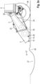
- Fig. 2a the ground between the knife 13 and the front wheels 26 is flat, and the driver assistance system 4 holds the cutting table 14 parallel to the ground and, based on distance measurement data from the sensing bracket 20, at a short distance from the ground, whereby the distance can be different depending on the control strategy used.
- the driver assistance system 4 detects an unevenness in the front of the combine harvester 1 via the sensor 21, e.g. B. a wild boar wallow with a central depression 27, surrounded by an elevation 28 made of loose excavated material.
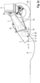
- the driver assistance system 4 can use the information about the survey 28 ahead in order to increase the setpoint for the distance to the ground detected by the feeler bar 20. According to an alternative strategy, this information is ignored, and in an effort to keep the distance detected by the sensing bracket 20 constant, the driver assistance system 4 first causes the actuator 24 to lower the inclined conveyor 3, so that, as in Fig. 2b shown, the rear edge of the cutting table 14 comes closer to the ground than in Fig. 2a .
- the cutting angle ⁇ can be adjusted to a negative value so that the cutting unit 2 can be raised much more slowly than if it had to be raised by the actuator 24 alone, i.e. the power required for the actuator 24 is much smaller than if the actuator 24 alone had to provide the necessary lifting of the cutting unit 2.
- the actuator 24 While the control of the actuator 23 is carried out proactively based on the topography of the apron detected by the sensor 21, the actuator 24, as described above, can only be controlled based on data from the stylus 20 is controlled, only react to the survey 28 when it touches the feeler bracket 20 under the cutting table 14.
- the knife 13 of the cutting unit 2 In order to successfully avoid the elevation 28, it is sufficient that at the moment in which the knife 13 of the cutting unit 2 reaches the elevation 28, the knife is higher than the elevation 28; the rear edge of the cutting table 14 can, as in Fig. 2b can be seen, lie even lower than the tip of the elevation 28. It is sufficient if the rear edge only reaches the necessary height while the cutting table 14 moves over the elevation 28, for example in response to a deflection of the feeler bracket 20 through the elevation 28.
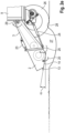
- the sensing bracket 20 has already passed the apex of the elevation 28 and would detect an increasing distance to the ground if the position remained the same. In the present situation, however, the pivoting movement about the axis 25 results in the sensing bracket 20 still detecting a decreasing distance to the ground and the driver assistance system 4 counteracting this by lifting the inclined conveyor 3.
- the driver assistance system 4 estimates the extent of the expected pitching movement based on the profile of the depression known from the data from the sensor 21, and controls the actuators 23, 24 in order to do so as in Fig. 2e shown to raise the cutting unit 2 so far that contact with the ground can be avoided.
- both actuators can work together to raise the knife 13 faster than the rear edge of the cutting table 14, thus minimizing the risk of damage to the knife.
- the pitching movement takes place while grain is being transferred by means of the transfer pipe 32 onto a transport vehicle driving alongside the combine harvester 1, and the transfer pipe 32 follows the pitching movement, this can result in grain missing the accompanying vehicle.
- the driver assistance system 4 together with the Fig. 2e
- the lifting shown controls a pivoting movement of the transfer tube 32 against the direction of travel. By superimposing this backward movement with the forward pitching movement, the point of impact of the grain on the transport vehicle can be kept largely constant and grain loss during transfer can be avoided.
- a positive cutting angle ⁇ is, on the one hand, desirable in order to - especially if the position of the actuator 24 is controlled by the feeler bracket 20 - at a given Deflection of the feeler bar allows the knife 13 to be placed close to the ground and to be able to pick up crops with little loss.
- the small distance from the ground can make quick evasive maneuvers necessary to avoid ground contact and mean that the driving speed of the combine harvester has to be limited in order to to enable the cutting unit to adjust its position in a timely manner.
- the sensor 21 can also be designed to detect the height of the plant population. If this is lower than normal in front of the cutting unit 2, this may be an indication of lying plants. While a standing crop of grain can be harvested with a relatively large distance of the knives 12/13 from the ground and a cutting angle ⁇ close to 0, since the valuable grains are located at the upper end of the stalk away from the ground, the driver assistance system 4 increases the height of the grain at a locally low level Crop the cutting angle ⁇ in order to bring the knives 12/13 closer to the ground and thus also be able to pick up ears that are close to the ground. In order to be able to react in a timely manner to uneven ground detected by the sensor 21 in this position, it may be necessary for the driver assistance system 4 to also reduce the driving speed of the combine harvester 1 during the transition to the increased cutting angle.
- the sensor 21 detects weeds in the crop to be harvested, it may be useful to make the cutting angle ⁇ negative and possibly also to raise the inclined conveyor 3 so that the weeds pass uncut under the cutting unit 2 and do not contaminate the harvest.
- the driver assistance system 4 of the combine harvester 1 shown as a block diagram serves at least to control the cutting unit 2, preferably also other units such as the threshing unit 5, the separation stage 6 and the cleaning stage 8.
- the driver assistance system 4 comprises a memory 4a for storing data - i.e. a memory in the information technology sense - and a computing device 4b for processing the data stored in the memory 4a.
- the driver assistance system 4 is set up to support a driver 7 of the combine harvester 1 in its operation.
- the actuators 23, 24 can be actuated individually or simultaneously by the driver assistance system 4 as above, for example to vary the cutting angle ⁇ while maintaining the height of the knives above the ground or to change the height above the ground while keeping the cutting angle ⁇ constant .
- the memory 4a contains various control strategies at least for the cutting unit 2.
- the control strategies can also include algorithms for controlling the threshing unit 5 and the cleaning stage 6 in accordance with the nature of the crop flow supplied by the cutting unit 2; However, these are not described here because they are not directly related to the invention.
- Each control strategy includes an algorithm for setting the height and cutting angle of the cutting unit 2 depending on the measurement results of the sensors 20, 21.
- the algorithms vary depending on the sensors fitted to the combine harvester. For example, an algorithm that relies solely on measured values from the sensor bracket 20 to prevent the cutting unit 2 from coming into contact with the ground will generally set a different height of the blades 12/13 above the ground to achieve a predetermined level of safety against contact with the ground than an algorithm that also has measured values of the soil profile in front of the cutting unit 2 from the sensor 21 available and that can trigger a sufficiently rapid raising of the cutting unit when a rise in the ground in front of the cutting unit 2 is detected.
- An algorithm that is based on data from the sensor 21 should control the position of the cutting unit differently depending on whether the soil surface detected by the sensor 21 is actually that of the soil or possibly that of a layer of mulch or residues of a previous crop lying on top of it, which should under no circumstances be picked up by the cutting unit 2 and fed to the threshing unit.
- the senor 21 can also be set up to detect an average height above the ground of fruit heads of the crop in a spatially resolved manner, so that the driver assistance system 4 can use this data to lower the height of the cutting unit if necessary in order to pick up the ears of grain from lying grain.
- At least two algorithms A 1 , A 2 are made available according to the invention, of which the algorithm A 1 is optimized for the most complete capture of the crop, but tends to be one at the expense of the ground clearance of the cutting unit 2 to set a high cutting angle or, in order to pick up low-lying crops, to accept a height of the cutting unit above the ground, which can lead to ground contact if it collapses, whereas algorithm A 2 is optimized to avoid ground contact, but if necessary, losses of crop must accept.
- the computing device 4b controls according to Fig. 3 a user interface 30 in the driver's cab to display an image with at least one slider 32 on a screen 31.
- the slider 32 beyond On the one hand, buttons 33, 34 assigned to the edge of the screen 31 can be used - if more than the algorithms A 1 , A 2 are available for selection - to assign an algorithm to each stop position of the slider, according to which the driver assistance system 4 controls the cutting unit 2, in particular the height of the knives 12/13 and the cutting angle ⁇ , controls when an adjusting button 35 of the slider is in a stop position adjacent to this button 33, 34.
- the same keys 33, 34 can be used to gradually shift the position of the adjusting knob 35 in the direction of the tapped key by tapping once or several times and thus determine a weighting factor c with which the keys 33, 34 assigned algorithms A 1 , A 2 influence the control of the cutting unit 2.
- the slider can also be provided as a physical component, or the screen 31 can be touch-sensitive, so that the driver 7 can move the displayed control button 35 by directly touching it and pulling it back and forth with a finger movement.
- the driver 7 can, in view of the field area to be worked, possibly also by drawing on experience gained during previous processing of the same area or during the current processing of this area, assess the extent to which the area meets the application requirements for algorithm A 1 or A 2 and adjust the slider 32 accordingly before starting to work the area or even during processing.
- the driver notices while working on the area that the flexibility is different than expected, he can continuously adapt the control of the cutting unit 2, for example by tapping the button 32 to select the algorithm A 1 or by tapping the key 33 to select the weighting factor c changed.
- both algorithms A 1 , A 2 use a uniform calculation rule to calculate a provisional cutting angle, but limit this by different upper limits ⁇ max1 , ⁇ max2 in order to achieve the target cutting angle ⁇ actually used to control the cutting unit 2 * and that the position of the control knob 34 determines an interpolated upper limit ⁇ max * based on a calculation rule as a function of the first and second upper limits ⁇ max1 , ⁇ max2 , whereby the weighting variable c determines the influence of the first and second extreme values ⁇ max1 , ⁇ max2 is determined on the result of the calculation rule.
- the calculation rule can be a weighted averaging.
- the target cutting angle ⁇ * is calculated by interpolating the angles ⁇ 1 and ⁇ 2 obtained according to the algorithms A 1 , A 2 and - if these are different - every change in the weighting factor c is a change in the target Cutting angle ⁇ * causes a change in the weighting factor c here as long as it is below a current interpolated upper limit ⁇ max before and after the change.
Landscapes
- Life Sciences & Earth Sciences (AREA)
- Environmental Sciences (AREA)
- Harvester Elements (AREA)
Applications Claiming Priority (1)
| Application Number | Priority Date | Filing Date | Title |
|---|---|---|---|
| DE102022125094.6A DE102022125094A1 (de) | 2022-09-29 | 2022-09-29 | Landwirtschaftliche Erntemaschine |
Publications (2)
| Publication Number | Publication Date |
|---|---|
| EP4344532A1 true EP4344532A1 (fr) | 2024-04-03 |
| EP4344532B1 EP4344532B1 (fr) | 2026-01-28 |
Family
ID=87426899
Family Applications (1)
| Application Number | Title | Priority Date | Filing Date |
|---|---|---|---|
| EP23186389.5A Active EP4344532B1 (fr) | 2022-09-29 | 2023-07-19 | Récolteuse agricole |
Country Status (3)
| Country | Link |
|---|---|
| US (1) | US20240107944A1 (fr) |
| EP (1) | EP4344532B1 (fr) |
| DE (1) | DE102022125094A1 (fr) |
Citations (8)
| Publication number | Priority date | Publication date | Assignee | Title |
|---|---|---|---|---|
| EP1374661B1 (fr) | 2002-06-19 | 2008-10-01 | CLAAS Selbstfahrende Erntemaschinen GmbH | Procédé et appareil pour le réglage de la position d'un dispositif ramasseur dans une récolteuse |
| DE102015113527A1 (de) | 2015-08-17 | 2017-02-23 | Claas Selbstfahrende Erntemaschinen Gmbh | Landwirtschaftliche Erntemaschine |
| EP3569049A1 (fr) * | 2018-05-16 | 2019-11-20 | CLAAS Selbstfahrende Erntemaschinen GmbH | Engin de travail agricole |
| US20200077584A1 (en) * | 2018-09-12 | 2020-03-12 | Deere & Company | Header position control with dynamicaly adapted sensitivity |
| EP3766329A1 (fr) * | 2019-07-15 | 2021-01-20 | CLAAS Selbstfahrende Erntemaschinen GmbH | Engin d'abattage-façonnage agricole |
| DE102020203524A1 (de) * | 2020-03-19 | 2021-09-23 | Deere & Company | Dämpfung von Nickschwingungen eines Arbeitsfahrzeugs durch Geschwindigkeitsänderung und Verstellung eines Elements unter Berücksichtigung der Betriebsart |
| EP3566564B1 (fr) * | 2018-05-08 | 2022-05-11 | CLAAS Selbstfahrende Erntemaschinen GmbH | Moissonneuse-batteuse et procédé de fonctionnement d'une moissonneuse-batteuse |
| US20220240446A1 (en) * | 2021-02-03 | 2022-08-04 | Cnh Industrial America Llc | Header fore/aft tilt control for combine harvester |
Family Cites Families (3)
| Publication number | Priority date | Publication date | Assignee | Title |
|---|---|---|---|---|
| US6615570B2 (en) * | 2001-06-28 | 2003-09-09 | Deere & Company | Header position control with forward contour prediction |
| DE102012214079A1 (de) * | 2012-08-08 | 2014-02-13 | Zürn Harvesting Gmbh & Co. Kg | Schneidwerk |
| GB202009977D0 (en) * | 2020-06-30 | 2020-08-12 | Agco Int Gmbh | Harvesters, harvesting headers, and methods of operating agricultural machines using crop lifters |
-
2022
- 2022-09-29 DE DE102022125094.6A patent/DE102022125094A1/de active Pending
-
2023
- 2023-07-19 EP EP23186389.5A patent/EP4344532B1/fr active Active
- 2023-09-29 US US18/374,820 patent/US20240107944A1/en active Pending
Patent Citations (8)
| Publication number | Priority date | Publication date | Assignee | Title |
|---|---|---|---|---|
| EP1374661B1 (fr) | 2002-06-19 | 2008-10-01 | CLAAS Selbstfahrende Erntemaschinen GmbH | Procédé et appareil pour le réglage de la position d'un dispositif ramasseur dans une récolteuse |
| DE102015113527A1 (de) | 2015-08-17 | 2017-02-23 | Claas Selbstfahrende Erntemaschinen Gmbh | Landwirtschaftliche Erntemaschine |
| EP3566564B1 (fr) * | 2018-05-08 | 2022-05-11 | CLAAS Selbstfahrende Erntemaschinen GmbH | Moissonneuse-batteuse et procédé de fonctionnement d'une moissonneuse-batteuse |
| EP3569049A1 (fr) * | 2018-05-16 | 2019-11-20 | CLAAS Selbstfahrende Erntemaschinen GmbH | Engin de travail agricole |
| US20200077584A1 (en) * | 2018-09-12 | 2020-03-12 | Deere & Company | Header position control with dynamicaly adapted sensitivity |
| EP3766329A1 (fr) * | 2019-07-15 | 2021-01-20 | CLAAS Selbstfahrende Erntemaschinen GmbH | Engin d'abattage-façonnage agricole |
| DE102020203524A1 (de) * | 2020-03-19 | 2021-09-23 | Deere & Company | Dämpfung von Nickschwingungen eines Arbeitsfahrzeugs durch Geschwindigkeitsänderung und Verstellung eines Elements unter Berücksichtigung der Betriebsart |
| US20220240446A1 (en) * | 2021-02-03 | 2022-08-04 | Cnh Industrial America Llc | Header fore/aft tilt control for combine harvester |
Also Published As
| Publication number | Publication date |
|---|---|
| US20240107944A1 (en) | 2024-04-04 |
| DE102022125094A1 (de) | 2024-04-04 |
| EP4344532B1 (fr) | 2026-01-28 |
Similar Documents
| Publication | Publication Date | Title |
|---|---|---|
| EP3560314B1 (fr) | Mécanisme de coupe à réglage automatique de l'orientation de dent de rabatteur | |
| EP3593620B1 (fr) | Système de récolte | |
| EP3300580B2 (fr) | Moissonneuse-batteuse pourvue de barre de coupe et dispositif de commande d'une barre de coupe | |
| EP3494771B1 (fr) | Dispositif de hauteur de coupe automatique | |
| EP3403485A1 (fr) | Dispositif d'auto-apprentissage, prenant en considération les entrées de correction destiné au contrôle automatique d'un paramètre de travail d'un dispositif de transport de produit de la récolte et/ou de traitement | |
| EP1269823A1 (fr) | Système de réglage d'une tête de récolte d'une machine de récolte | |
| EP1374661A1 (fr) | Procédé et appareil pour le réglage de la position d'un dispositif ramasseur dans une récolteuse | |
| EP3598886B1 (fr) | Engin d'abattage-façonnage automoteur | |
| EP4136956A1 (fr) | Procédé de fonctionnement d'une machine de récolte automotrice et machine de récolte automotrice | |
| DE102004059543A1 (de) | Landwirtschaftliche Arbeitsmaschine | |
| DE102012011591B4 (de) | Aufnahmevorrichtung für eine landwirtschaftliche Erntemaschine | |
| EP0713639B1 (fr) | Dispositif palpeur pour le guidage latéral automatique d'un moissonneuse automotrice | |
| DE2807250A1 (de) | Vorrichtung zum fuehren einer erntemaschine entlang von pflanzenreihen | |
| DE102021120012A1 (de) | Anordnung zur Steuerung der Höhe eines Erntevorsatzes zur Ernte stängelartigen Ernteguts | |
| EP4252519B1 (fr) | Moissonneuse agricole et procédé de commande d'une moissonneuse agricole | |
| EP1261248B1 (fr) | Dispositif pour la reproduction du sol destine a des outils adaptables de moissonneuses | |
| EP4344532B1 (fr) | Récolteuse agricole | |
| EP4344531B1 (fr) | Récolteuse agricole | |
| EP0363916B1 (fr) | Dispositif pour récolter les fruits des champs en particulier des betteraves | |
| EP4480300A1 (fr) | Diviseur d'hals d'un dispositif de récolte avec pointe de diviseur | |
| EP1595434A1 (fr) | Agencement de rabatteur | |
| BE1027478B1 (de) | Feldhäcksler mit Auswurfkrümmer und positionsverstellbarer Kabine | |
| WO2024235394A1 (fr) | Accessoire de ramassage pour une machine de récolte | |
| DE102022119175A1 (de) | Schneidwerk für eine erntemaschine mit automatischer haspelfingerneigungseinstellung auf positionsbasis | |
| DE102021134284A1 (de) | Pick-Up-Vorsatzgerät für eine Erntemaschine |
Legal Events
| Date | Code | Title | Description |
|---|---|---|---|
| PUAI | Public reference made under article 153(3) epc to a published international application that has entered the european phase |
Free format text: ORIGINAL CODE: 0009012 |
|
| STAA | Information on the status of an ep patent application or granted ep patent |
Free format text: STATUS: THE APPLICATION HAS BEEN PUBLISHED |
|
| AK | Designated contracting states |
Kind code of ref document: A1 Designated state(s): AL AT BE BG CH CY CZ DE DK EE ES FI FR GB GR HR HU IE IS IT LI LT LU LV MC ME MK MT NL NO PL PT RO RS SE SI SK SM TR |
|
| P01 | Opt-out of the competence of the unified patent court (upc) registered |
Effective date: 20240403 |
|
| STAA | Information on the status of an ep patent application or granted ep patent |
Free format text: STATUS: REQUEST FOR EXAMINATION WAS MADE |
|
| 17P | Request for examination filed |
Effective date: 20241004 |
|
| RBV | Designated contracting states (corrected) |
Designated state(s): AL AT BE BG CH CY CZ DE DK EE ES FI FR GB GR HR HU IE IS IT LI LT LU LV MC ME MK MT NL NO PL PT RO RS SE SI SK SM TR |
|
| STAA | Information on the status of an ep patent application or granted ep patent |
Free format text: STATUS: EXAMINATION IS IN PROGRESS |
|
| 17Q | First examination report despatched |
Effective date: 20250225 |
|
| GRAP | Despatch of communication of intention to grant a patent |
Free format text: ORIGINAL CODE: EPIDOSNIGR1 |
|
| STAA | Information on the status of an ep patent application or granted ep patent |
Free format text: STATUS: GRANT OF PATENT IS INTENDED |
|
| INTG | Intention to grant announced |
Effective date: 20250829 |
|
| GRAS | Grant fee paid |
Free format text: ORIGINAL CODE: EPIDOSNIGR3 |
|
| GRAA | (expected) grant |
Free format text: ORIGINAL CODE: 0009210 |
|
| STAA | Information on the status of an ep patent application or granted ep patent |
Free format text: STATUS: THE PATENT HAS BEEN GRANTED |
|
| AK | Designated contracting states |
Kind code of ref document: B1 Designated state(s): AL AT BE BG CH CY CZ DE DK EE ES FI FR GB GR HR HU IE IS IT LI LT LU LV MC ME MK MT NL NO PL PT RO RS SE SI SK SM TR |
|
| REG | Reference to a national code |
Ref country code: CH Ref legal event code: F10 Free format text: ST27 STATUS EVENT CODE: U-0-0-F10-F00 (AS PROVIDED BY THE NATIONAL OFFICE) Effective date: 20260128 Ref country code: GB Ref legal event code: FG4D Free format text: NOT ENGLISH |
|
| REG | Reference to a national code |
Ref country code: DE Ref legal event code: R096 Ref document number: 502023002860 Country of ref document: DE |
|
| REG | Reference to a national code |
Ref country code: IE Ref legal event code: FG4D Free format text: LANGUAGE OF EP DOCUMENT: GERMAN |