EP4344926B1 - Machine de travail dotée d'un entraînement électrique - Google Patents
Machine de travail dotée d'un entraînement électrique Download PDFInfo
- Publication number
- EP4344926B1 EP4344926B1 EP23195640.0A EP23195640A EP4344926B1 EP 4344926 B1 EP4344926 B1 EP 4344926B1 EP 23195640 A EP23195640 A EP 23195640A EP 4344926 B1 EP4344926 B1 EP 4344926B1
- Authority
- EP
- European Patent Office
- Prior art keywords
- connection
- work machine
- mating
- supply line
- traction drive
- Prior art date
- Legal status (The legal status is an assumption and is not a legal conclusion. Google has not performed a legal analysis and makes no representation as to the accuracy of the status listed.)
- Active
Links
Images




Classifications
-
- B—PERFORMING OPERATIONS; TRANSPORTING
- B60—VEHICLES IN GENERAL
- B60R—VEHICLES, VEHICLE FITTINGS, OR VEHICLE PARTS, NOT OTHERWISE PROVIDED FOR
- B60R16/00—Electric or fluid circuits specially adapted for vehicles and not otherwise provided for; Arrangement of elements of electric or fluid circuits specially adapted for vehicles and not otherwise provided for
- B60R16/02—Electric or fluid circuits specially adapted for vehicles and not otherwise provided for; Arrangement of elements of electric or fluid circuits specially adapted for vehicles and not otherwise provided for electric constitutive elements
- B60R16/03—Electric or fluid circuits specially adapted for vehicles and not otherwise provided for; Arrangement of elements of electric or fluid circuits specially adapted for vehicles and not otherwise provided for electric constitutive elements for supply of electrical power to vehicle subsystems or for
-
- B—PERFORMING OPERATIONS; TRANSPORTING
- B60—VEHICLES IN GENERAL
- B60L—PROPULSION OF ELECTRICALLY-PROPELLED VEHICLES; SUPPLYING ELECTRIC POWER FOR AUXILIARY EQUIPMENT OF ELECTRICALLY-PROPELLED VEHICLES; ELECTRODYNAMIC BRAKE SYSTEMS FOR VEHICLES IN GENERAL; MAGNETIC SUSPENSION OR LEVITATION FOR VEHICLES; MONITORING OPERATING VARIABLES OF ELECTRICALLY-PROPELLED VEHICLES; ELECTRIC SAFETY DEVICES FOR ELECTRICALLY-PROPELLED VEHICLES
- B60L3/00—Electric devices on electrically-propelled vehicles for safety purposes; Monitoring operating variables, e.g. speed, deceleration or energy consumption
- B60L3/04—Cutting off the power supply under fault conditions
-
- B—PERFORMING OPERATIONS; TRANSPORTING
- B60—VEHICLES IN GENERAL
- B60K—ARRANGEMENT OR MOUNTING OF PROPULSION UNITS OR OF TRANSMISSIONS IN VEHICLES; ARRANGEMENT OR MOUNTING OF PLURAL DIVERSE PRIME-MOVERS IN VEHICLES; AUXILIARY DRIVES FOR VEHICLES; INSTRUMENTATION OR DASHBOARDS FOR VEHICLES; ARRANGEMENTS IN CONNECTION WITH COOLING, AIR INTAKE, GAS EXHAUST OR FUEL SUPPLY OF PROPULSION UNITS IN VEHICLES
- B60K7/00—Disposition of motor in, or adjacent to, traction wheel
- B60K7/0007—Disposition of motor in, or adjacent to, traction wheel the motor being electric
-
- B—PERFORMING OPERATIONS; TRANSPORTING
- B60—VEHICLES IN GENERAL
- B60L—PROPULSION OF ELECTRICALLY-PROPELLED VEHICLES; SUPPLYING ELECTRIC POWER FOR AUXILIARY EQUIPMENT OF ELECTRICALLY-PROPELLED VEHICLES; ELECTRODYNAMIC BRAKE SYSTEMS FOR VEHICLES IN GENERAL; MAGNETIC SUSPENSION OR LEVITATION FOR VEHICLES; MONITORING OPERATING VARIABLES OF ELECTRICALLY-PROPELLED VEHICLES; ELECTRIC SAFETY DEVICES FOR ELECTRICALLY-PROPELLED VEHICLES
- B60L1/00—Supplying electric power to auxiliary equipment of vehicles
- B60L1/003—Supplying electric power to auxiliary equipment of vehicles to auxiliary motors, e.g. for pumps, compressors
-
- B—PERFORMING OPERATIONS; TRANSPORTING
- B60—VEHICLES IN GENERAL
- B60L—PROPULSION OF ELECTRICALLY-PROPELLED VEHICLES; SUPPLYING ELECTRIC POWER FOR AUXILIARY EQUIPMENT OF ELECTRICALLY-PROPELLED VEHICLES; ELECTRODYNAMIC BRAKE SYSTEMS FOR VEHICLES IN GENERAL; MAGNETIC SUSPENSION OR LEVITATION FOR VEHICLES; MONITORING OPERATING VARIABLES OF ELECTRICALLY-PROPELLED VEHICLES; ELECTRIC SAFETY DEVICES FOR ELECTRICALLY-PROPELLED VEHICLES
- B60L3/00—Electric devices on electrically-propelled vehicles for safety purposes; Monitoring operating variables, e.g. speed, deceleration or energy consumption
-
- B—PERFORMING OPERATIONS; TRANSPORTING
- B60—VEHICLES IN GENERAL
- B60L—PROPULSION OF ELECTRICALLY-PROPELLED VEHICLES; SUPPLYING ELECTRIC POWER FOR AUXILIARY EQUIPMENT OF ELECTRICALLY-PROPELLED VEHICLES; ELECTRODYNAMIC BRAKE SYSTEMS FOR VEHICLES IN GENERAL; MAGNETIC SUSPENSION OR LEVITATION FOR VEHICLES; MONITORING OPERATING VARIABLES OF ELECTRICALLY-PROPELLED VEHICLES; ELECTRIC SAFETY DEVICES FOR ELECTRICALLY-PROPELLED VEHICLES
- B60L3/00—Electric devices on electrically-propelled vehicles for safety purposes; Monitoring operating variables, e.g. speed, deceleration or energy consumption
- B60L3/0023—Detecting, eliminating, remedying or compensating for drive train abnormalities, e.g. failures within the drive train
-
- B—PERFORMING OPERATIONS; TRANSPORTING
- B60—VEHICLES IN GENERAL
- B60L—PROPULSION OF ELECTRICALLY-PROPELLED VEHICLES; SUPPLYING ELECTRIC POWER FOR AUXILIARY EQUIPMENT OF ELECTRICALLY-PROPELLED VEHICLES; ELECTRODYNAMIC BRAKE SYSTEMS FOR VEHICLES IN GENERAL; MAGNETIC SUSPENSION OR LEVITATION FOR VEHICLES; MONITORING OPERATING VARIABLES OF ELECTRICALLY-PROPELLED VEHICLES; ELECTRIC SAFETY DEVICES FOR ELECTRICALLY-PROPELLED VEHICLES
- B60L50/00—Electric propulsion with power supplied within the vehicle
- B60L50/50—Electric propulsion with power supplied within the vehicle using propulsion power supplied by batteries or fuel cells
-
- B—PERFORMING OPERATIONS; TRANSPORTING
- B62—LAND VEHICLES FOR TRAVELLING OTHERWISE THAN ON RAILS
- B62D—MOTOR VEHICLES; TRAILERS
- B62D55/00—Endless track vehicles
- B62D55/06—Endless track vehicles with tracks without ground wheels
-
- B—PERFORMING OPERATIONS; TRANSPORTING
- B62—LAND VEHICLES FOR TRAVELLING OTHERWISE THAN ON RAILS
- B62D—MOTOR VEHICLES; TRAILERS
- B62D55/00—Endless track vehicles
- B62D55/08—Endless track units; Parts thereof
-
- E—FIXED CONSTRUCTIONS
- E02—HYDRAULIC ENGINEERING; FOUNDATIONS; SOIL SHIFTING
- E02F—DREDGING; SOIL-SHIFTING
- E02F9/00—Component parts of dredgers or soil-shifting machines, not restricted to one of the kinds covered by groups E02F3/00 - E02F7/00
- E02F9/08—Superstructures; Supports for superstructures
- E02F9/0858—Arrangement of component parts installed on superstructures not otherwise provided for, e.g. electric components, fenders, air-conditioning units
-
- E—FIXED CONSTRUCTIONS
- E02—HYDRAULIC ENGINEERING; FOUNDATIONS; SOIL SHIFTING
- E02F—DREDGING; SOIL-SHIFTING
- E02F9/00—Component parts of dredgers or soil-shifting machines, not restricted to one of the kinds covered by groups E02F3/00 - E02F7/00
- E02F9/20—Drives; Control devices
- E02F9/2058—Electric or electro-mechanical or mechanical control devices of vehicle sub-units
- E02F9/2062—Control of propulsion units
- E02F9/207—Control of propulsion units of the type electric propulsion units, e.g. electric motors or generators
-
- E—FIXED CONSTRUCTIONS
- E02—HYDRAULIC ENGINEERING; FOUNDATIONS; SOIL SHIFTING
- E02F—DREDGING; SOIL-SHIFTING
- E02F9/00—Component parts of dredgers or soil-shifting machines, not restricted to one of the kinds covered by groups E02F3/00 - E02F7/00
- E02F9/20—Drives; Control devices
- E02F9/2058—Electric or electro-mechanical or mechanical control devices of vehicle sub-units
- E02F9/2087—Control of vehicle steering
-
- E—FIXED CONSTRUCTIONS
- E02—HYDRAULIC ENGINEERING; FOUNDATIONS; SOIL SHIFTING
- E02F—DREDGING; SOIL-SHIFTING
- E02F9/00—Component parts of dredgers or soil-shifting machines, not restricted to one of the kinds covered by groups E02F3/00 - E02F7/00
- E02F9/20—Drives; Control devices
- E02F9/2058—Electric or electro-mechanical or mechanical control devices of vehicle sub-units
- E02F9/2095—Control of electric, electro-mechanical or mechanical equipment not otherwise provided for, e.g. ventilators, electro-driven fans
-
- B—PERFORMING OPERATIONS; TRANSPORTING
- B60—VEHICLES IN GENERAL
- B60K—ARRANGEMENT OR MOUNTING OF PROPULSION UNITS OR OF TRANSMISSIONS IN VEHICLES; ARRANGEMENT OR MOUNTING OF PLURAL DIVERSE PRIME-MOVERS IN VEHICLES; AUXILIARY DRIVES FOR VEHICLES; INSTRUMENTATION OR DASHBOARDS FOR VEHICLES; ARRANGEMENTS IN CONNECTION WITH COOLING, AIR INTAKE, GAS EXHAUST OR FUEL SUPPLY OF PROPULSION UNITS IN VEHICLES
- B60K7/00—Disposition of motor in, or adjacent to, traction wheel
- B60K2007/0038—Disposition of motor in, or adjacent to, traction wheel the motor moving together with the wheel axle
-
- B—PERFORMING OPERATIONS; TRANSPORTING
- B60—VEHICLES IN GENERAL
- B60L—PROPULSION OF ELECTRICALLY-PROPELLED VEHICLES; SUPPLYING ELECTRIC POWER FOR AUXILIARY EQUIPMENT OF ELECTRICALLY-PROPELLED VEHICLES; ELECTRODYNAMIC BRAKE SYSTEMS FOR VEHICLES IN GENERAL; MAGNETIC SUSPENSION OR LEVITATION FOR VEHICLES; MONITORING OPERATING VARIABLES OF ELECTRICALLY-PROPELLED VEHICLES; ELECTRIC SAFETY DEVICES FOR ELECTRICALLY-PROPELLED VEHICLES
- B60L2200/00—Type of vehicles
- B60L2200/40—Working vehicles
-
- B—PERFORMING OPERATIONS; TRANSPORTING
- B60—VEHICLES IN GENERAL
- B60L—PROPULSION OF ELECTRICALLY-PROPELLED VEHICLES; SUPPLYING ELECTRIC POWER FOR AUXILIARY EQUIPMENT OF ELECTRICALLY-PROPELLED VEHICLES; ELECTRODYNAMIC BRAKE SYSTEMS FOR VEHICLES IN GENERAL; MAGNETIC SUSPENSION OR LEVITATION FOR VEHICLES; MONITORING OPERATING VARIABLES OF ELECTRICALLY-PROPELLED VEHICLES; ELECTRIC SAFETY DEVICES FOR ELECTRICALLY-PROPELLED VEHICLES
- B60L2220/00—Electrical machine types; Structures or applications thereof
- B60L2220/40—Electrical machine applications
- B60L2220/42—Electrical machine applications with use of more than one motor
-
- E—FIXED CONSTRUCTIONS
- E02—HYDRAULIC ENGINEERING; FOUNDATIONS; SOIL SHIFTING
- E02F—DREDGING; SOIL-SHIFTING
- E02F3/00—Dredgers; Soil-shifting machines
- E02F3/04—Dredgers; Soil-shifting machines mechanically-driven
- E02F3/46—Dredgers; Soil-shifting machines mechanically-driven with reciprocating digging or scraping elements moved by cables or hoisting ropes ; Drives or control devices therefor
- E02F3/58—Component parts
-
- E—FIXED CONSTRUCTIONS
- E02—HYDRAULIC ENGINEERING; FOUNDATIONS; SOIL SHIFTING
- E02F—DREDGING; SOIL-SHIFTING
- E02F9/00—Component parts of dredgers or soil-shifting machines, not restricted to one of the kinds covered by groups E02F3/00 - E02F7/00
- E02F9/20—Drives; Control devices
- E02F9/2058—Electric or electro-mechanical or mechanical control devices of vehicle sub-units
- E02F9/2091—Control of energy storage means for electrical energy, e.g. battery or capacitors
Definitions
- the present invention relates to a working machine, in particular a cable excavator, according to the preamble of claim 1.
- the electric travel drives are usually supplied with power and, if necessary, coolant from the undercarriage.
- the travel drives are typically connected to the high-voltage (HV) electrical system of the work machine, whereby power electronics located on or in the undercarriage can handle communication with the travel drives and the modulation of current and voltage to supply the travel drives.
- the travel drives are powered via power supply lines, typically three AC-phase power cables, which are connected to inverters of the power electronics.
- power supply lines typically three AC-phase power cables, which are connected to inverters of the power electronics.
- coolant lines control lines for controlling the Drives and/or signal lines for transmitting sensor signals, for example.
- the crawler supports are removed from the center section for transport.
- such work machines can lift the crawler supports, which are transported to the construction site on a separate low-loader, for example, and partially scaffolded, onto the undercarriage themselves in a self-assembly operation.
- a separate low-loader for example, and partially scaffolded
- the object of the present invention is to increase the safety during assembly and disassembly of the crawler supports in generic electrified work machines and to make the assembly and disassembly of the crawler supports simple.
- US 2022/074163 A1 discloses a work machine, in particular a cable excavator, with an undercarriage which comprises a central part and two crawler carriers connected to the central part with an electric travel drive, wherein at least one supply line runs from the central part to the travel drive.
- a work machine which comprises an undercarriage with a central section and at least one crawler carrier connected to the central section.
- the work machine can be, for example, a cable excavator.
- the at least one crawler carrier has at least one electric drive, which in particular drives a crawler chain of the crawler carrier.
- the drive is in particular an electric motor.
- the drive is supplied via at least one supply line from the central section of the work machine, in particular with high voltage or current from an HV on-board network. of the work machine.
- the supply line is connected to the drive via a connector and can therefore be disconnected from the drive, for example, to dismantle the crawler carrier.
- the work machine is provided with an electrical interlock circuit connected to the travel drive via the first connection.
- the travel drive is included in the interlock circuit via the first connection. If the first connection of the supply line is disconnected, the interlock circuit is interrupted.
- the work machine further comprises a mating connector module arranged on the undercarriage with a first mating connection for connection to the first connection of the supply line previously disconnected from the traction drive (or a connection on the traction drive side).
- the mating connector module is designed to electrically bridge the interlock circuit interrupted by a disconnection from the traction drive by connecting the first connection to the first mating connection, i.e., to close the interlock circuit.
- the interlock circuit represents, in particular, a separate, closed electrical circuit whose interlock line runs through the first connection or a connector having the first connection to the drive and back again.
- An interruption in the closed interlock circuit results in a change in a read parameter of the interlock circuit, which allows the interruption to be detected and, if necessary, appropriate action to be taken.
- the interlock circuit is interrupted, which can be detected by appropriate evaluation electronics.
- a power source e.g., a battery
- a battery can be disconnected from the vehicle's electrical system, so that dangerous voltage is no longer present at the open first connection.
- the mating connector module Since in certain situations it is desired to operate the work machine even when the crawler carrier is disassembled, for example during self-assembly or self-dismantling of the crawler carrier, the mating connector module according to the invention provides a way to safely stow or "park" the open end of the supply line.
- the open first connection is connected to the corresponding mating connection of the mating connector module. This eliminates the danger posed by the first connection, as it is no longer open but securely connected to the mating connection.
- the mating connector module bridges the interlock circuit, thereby enabling safe operation of the work machine in a partially assembled state.
- the mating connector module has, in particular, a corresponding interlock line that bridges or closes the interlock circuit.
- the interlock line of the mating connector module i.e., the interlock circuit including the mating connector module
- the mating connector module is located on the undercarriage, preferably in the center section in a position easily accessible to the operating personnel, the supply line can be quickly and easily stowed away after being disconnected from the drive system. There are no separate parts that could get lost and complicate operation.
- At least one supply line is designed as a power supply line for supplying power to the traction drive.
- the power supply line supplies the traction drive with power from the internal HV electrical system of the work machine.
- three power supply lines are provided, which are designed in particular as AC phase cables.
- the at least one power supply line is preferably connected to at least one inverter. This is ideally arranged in or on the center section of the undercarriage.
- At least one supply line is designed as a signal line for transmitting control signals to the travel drive and/or for transmitting sensor signals.
- Said control system can be an inverter or a separate control unit.
- Such a control line serves, in particular, to control the travel drive.
- Multiple control and/or signal lines can be provided to transmit different signals.
- One or more signal lines can be a resolver cable.
- the travel drive is detachably connected to at least one first supply line via a first connection and to at least one second supply line via a second connection.
- the first connection preferably serves to supply energy to the travel drive (i.e. it is connected to one or more energy supply lines) and the second connection to transmit signals, for example control signals for controlling the travel drive or sensor signals.
- Different supply lines are therefore detachably connected to the travel drive in parallel via corresponding connections.
- more than two connections and a corresponding number of counter connections can be provided per travel drive.
- the mating connector module comprises a first mating connection for connection to the first connection and a second mating connection for connection to the second connection. This allows each connection of a supply line that remains open after disconnection from the drive system to be releasably connected to a corresponding mating connection of the mating connector module in order to safely store the module and to bridge the interlock circuit via the mating connector module.
- the first and second connections are formed on separate connectors and/or differently.
- several Power supply lines are connected to a common first connection.
- This can have a different shape than a second connection, which is connected to one or more signal lines.
- a wide variety of configurations are conceivable here, whereby, regardless of the exact design, a corresponding mating connection is provided on the mating connector module for each connection of a power line, particularly in the form of a simple plug connection.
- At least one locking device can be provided to fix the connections or supply lines connected to the mating connector module so that the connections cannot become loose unintentionally.
- a common interlock circuit is connected to the first and second mating connections and can be bridged in a current-conducting manner by simultaneously connecting the first and second connections to the first and second mating connections.
- the interlock circuit can only be closed by both connections being connected to the corresponding mating connections. If one of the connections is not connected to its mating connection, the common interlock circuit is interrupted. This ensures that any operation of the work machine in a partially equipped state can only take place when all supply lines are safely stowed in the mating connector module, i.e., for example, when both crawler supports are removed or attached.
- interlock circuits can be provided, with a first interlock circuit connected to the first mating terminal and a separate, second interlock circuit connected to the second mating terminal.
- Each interlock circuit can be bridged separately by connecting the respective terminal to the associated mating terminal.
- each supply line is assigned its own interlock circuit, so that different connection or fault states can be determined by appropriate evaluation of the interlock circuits.
- first terminal and the first mating terminal have interlock contacts that are electrically connected to one another when connected. If a second terminal and a second mating terminal are provided, as described above, these preferably also have corresponding interlock contacts.
- an evaluation unit is provided which is connected to the interlock circuit and is configured to detect an interruption in the interlock circuit. If multiple interlock circuits are provided, these can be analyzed by a common evaluation unit or, alternatively, each by its own evaluation unit.
- the evaluation unit is preferably further configured to disconnect a power source (for example a battery) from the on-board electrical system of the work machine upon detection of an interruption in the associated interlock circuit, so that no voltage is present at the open connections. If the interlock circuit is subsequently closed or bypassed, the evaluation unit can also detect this and, in particular, reconnect the power source to the on-board electrical system so that operation of the work machine is possible.
- the disconnection or connection of the power source can be initiated directly or indirectly by the evaluation unit, in the latter case, for example, through communication with a corresponding control unit that controls the disconnection or connection of the power source.
- the first connection is accessible from outside the center section and the crawler support and, in particular, is located outside the center section and crawler support when connected. This allows the supply lines to be easily and quickly detached from the respective connection points on the crawler support and/or center section, for example, when disassembling the crawler support. A connection is also achieved smoothly and quickly.
- a section of the at least one supply line adjacent to the first connection extends outside the center section and crawler support, i.e., in particular, outside the steel structure of the undercarriage, and is particularly designed to be movable or flexible.
- the at least one supply line is preferably designed such that the first connection can be connected either to the first mating connection of the mating connector module or to a connection arranged on the crawler support and connected to the travel drive. This allows the supply line to be easily and quickly connected to the mating connection after being disconnected from the travel drive.
- At least two crawler supports connected to the central section are provided, which are arranged in particular on opposite sides of the central section.
- the crawler supports each have at least one drive system, which is powered via at least one supply line.
- the mating connector module has two first mating connections for connection to the first connections of the respective supply lines.
- a common mating connector module is therefore provided for the various travel drives.
- the mating connector module can comprise several separate interlock circuits for the respective travel drives or several interlock circuit lines that can bridge the separate interlock circuits assigned to the respective travel drives separately from one another. This allows the work machine to be operated, for example, in a state in which one crawler carrier is mounted and its travel drive is connected, while the other crawler carrier is dismantled and the corresponding connections are still connected to the mating connector module.
- a common interlock circuit can be provided, so that all connections of the supply lines of all travel drives must be connected to the mating connector module simultaneously in order to close the interlock circuit.
- At least two separate mating connector modules each with a first mating connection for connection to the first connection of the respective supply line.
- a separate mating connector module is provided for each drive.
- the work machine has a corresponding number of interlock circuits, each of which is assigned a mating connector module.
- the at least one crawler support is detachably connected to the central section
- the work machine preferably comprises an upper carriage rotatably mounted on the undercarriage and is designed to carry out lifting work in self-assembly mode without mounted crawler supports using a boom or boom section mounted on the upper carriage, for example in order to lift the crawler supports from a low-loader to connection points on the central section.
- a power supply for the work function is preferably only activated when the interlock circuit is closed via the mating connector module. If, on the other hand, the interlock circuit is interrupted, the work function (e.g., operating a boom, a hoist winch, etc.) cannot be used or the power supply is deactivated.
- FIG. 1 A preferred embodiment of the work machine 10 according to the invention is shown in a side view.
- the embodiment shown is a cable excavator 10 with a mobile undercarriage 12 and an upper carriage 14 mounted on the undercarriage 12 so as to be rotatable about a vertical axis of rotation.
- the undercarriage 12 is in the Figure 3 shown in a perspective view.
- the boom of the cable excavator 10 is not shown here.
- the upper carriage 14 has a driver's cabin 17 and is connected to the crane by a slewing ring 15, which is Figure 3 can be seen, is rotatably connected to a central part 13 of the undercarriage 12.
- the crawler supports 20 have electric drive units 22, which drive the crawler tracks and control their position in the Figure 3 is only indicated by arrows.
- the drive systems 22 are, in particular, electric motors.
- the cable excavator 10 can have a central ballast 16 mounted on the middle section 13 at the front and rear between the crawler supports 20. This can be optionally attached or removed, depending on the application.
- the Figure 2 shows a side view of the uppercarriage 14 mounted on the center section 13, with the crawler supports 20 removed from the center section 13.
- the work machine is in a self-assembly state in which several (here four) hydraulic jack-up cylinders 18, which are vertically aligned and arranged on the center section 13, are extended.
- the partially rigged duty cycle crawler excavator 10 stands on the jack-up cylinders 18, which function as support feet and hold the center section 13 in an elevated position in which the crawler supports 20 can be attached laterally to the center section 13. Via a boom (or in particular a linkage piece of the boom) not shown here, the partially rigged duty cycle crawler excavator 10 can lift and move the crawler supports 20 independently in a self-assembly operation.
- the electric travel drives 22 are supplied and controlled from the center section 13 by an HV electrical system of the work machine 10.
- This can be a DC electrical system.
- the electrical system preferably extends from the center section 13 via slip ring contacts into the uppercarriage 14, where certain electrical drive components and consumers are also supplied. Therefore, electrical drive components and consumers in the uppercarriage 14 and the undercarriage 12, including the electric travel drives 22, are preferably supplied by the same electrical system.
- three power supply lines in the form of AC phase cables can be provided per traction drive 22, which supply the respective traction drive 22 with power from the HV on-board network.
- the power supply lines 40 run between the traction drives 22 and one or more inverters (not shown), which are preferably arranged in the central section 13. The inverters handle communication with the traction drives 22 and the modulation of current and voltage to supply the traction drives 22.
- control of the travel drives 22 can be performed via one or more control lines. Communication with the travel drives 22 can also be performed via the inverters or a separate control module. Additionally, one or more signal lines can be provided, for example, to transmit sensor signals from the travel drives 22 to a controller (or the inverters) in the central section 13.
- the electrical lines for supplying and controlling the travel drives 22 and, if applicable, for signal transmission are collectively referred to herein as supply lines 40.
- the supply lines 40 are not routed to the travel drives 22 in the steel structure of the undercarriage 12, but run outside of the central section 13 and crawler supports 20, as shown in Figure 3 is indicated.
- the supply lines 40 are preferably designed to be movable or flexible.
- the supply lines 40 are detachably connected to the drive units 22 via connections 41, 42.
- corresponding connectors are provided in The connectors 41, 42 are provided in the form of sockets and plugs, which are detachably connected to form electrically conductive connections.
- the connectors 41, 42 are arranged, in particular, outside the track carriers 20, so that they are easily accessible from the outside and can be unplugged (and connected) without great effort.
- each travel drive 22 can be connected to a cooling circuit, with two coolant lines running between the central section 13 and the travel drives 22, which supply the coolant to the travel drives 22 and transport the heated coolant back to the central section 13.
- the coolant lines preferably run parallel to the supply lines 40.
- the coolant lines are also preferably detachably connected to the travel drives via corresponding connections.
- the work machine 10 is equipped with a high-voltage interlock loop (HVIL for short; hereinafter referred to as interlock loop 50).
- the interlock loop 50 serves to monitor the plug connections in the high-voltage circuit of the work machine 10 and is intended to prevent hazards caused by unintentional or improper disconnection of an HV plug connection (i.e., the connections 41, 42 of the supply lines 40).
- the interlock loop 50 is designed as a closed electrical circuit that extends from the vehicle electrical system to the relevant electrical drives and consumers through the respective plug connections or connections 41, 42. extends through it.
- the terminals 41, 42 each have special interlock contacts, which are electrically connected to one another when the terminals 41, 42 are connected.
- Pins 41 and 42 do not necessarily have to be separate pins. In the simplest case, pins 41 and 42 can simply represent different pins, for example, "HVIL in” and "HVIL out.”
- the interlock circuit 50 is closed. If the interlock circuit 50 is interrupted, for example, by disconnecting a terminal 41, 42 of a supply line 40, this is detected by an evaluation unit (not shown) of the work machine 10 and, as a result, a power source (e.g., a battery) is disconnected from the vehicle electrical system. This de-energizes the system, and no voltage is present at the open terminal 41, 42.
- a power source e.g., a battery
- the power supply lines of the right and left drive units 22 can be connected via first connections 41, 41', and the signal lines of the right and left drive units 22 can be connected via second connections 42, 42'.
- the three power supply lines can have a common connector. In principle, individual connectors are also conceivable.
- the crawler supports 20 are removed and the first and second connections 41, 42 of the supply lines 40 are open. This interrupts the interlock circuit 50, meaning no power supply is available for self-assembly operation.
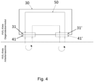
- a mating connector module 30 is provided according to the invention, which in this exemplary embodiment is arranged on the middle part 13 in the region of the middle part-side connection points of the supply lines 40, cf. Fig. 3
- the mating connector module 30 has matching connectors for the terminals 41, 42 of the supply lines 40.
- Interfaces in this embodiment in the form of a first mating connection 31 for connection to the first connection 41 and a second mating connection 32 for connection to the second connection 42 of the supply lines 40.
- the open ends of the supply lines 40 are simply connected to the mating connections 31, 32 of the mating connector module 30 and "parked" there for partially assembled operation.
- the mating connector module 30 is designed such that the interlock contacts of the connections 41, 42 are bridged in a conductive manner, thereby closing the interlock circuit 50. This ensures that the power supply of the on-board electrical system is available when the work machine 10 is partially assembled, for example, for self-assembly or disassembly of the crawler supports 20.
- the mating connector module 30 comprises a single interlock circuit 50 (more precisely, interlock lines to a single interlock circuit 50 of the work machine 10) and two first mating connections 31, 31' for the first connections 41, 41' of the right and left crawler supports 20.
- the curved arrows indicate that the interlock lines of the interlock circuit 50 run through the connections 41, 41' and mating connections 31, 31' into the mating connector module 30 and out again from it and also outside as a closed circuit.
- additional supply lines 40 are provided for signal transmission (e.g., control lines), these can optionally be connected to a separate mating connector module, which comprises interlock lines for the same or a separate interlock circuit 50, 50'.
- a common mating connector module 30 can comprise both first mating connections 31, 31' for the first connections 41, 41' and second mating connections 32, 32' for the second connections 42, 42' of the supply lines 40. This possibility is described in the Figures 5 and 6 shown, wherein in the second embodiment according to Fig. 5 a single, common interlock circuit 50 is provided, which is connected by all connections 41, 41', 42, 42' and mating connections 31, 31', 32, 32'. In this case, the interlock circuit 50 is only closed and the work machine 10 is thus ready for use if all supply lines 40 of the travel drives 22 are actually plugged into the mating connector module 30 via their first and second connections 41, 41', 42, 42'.
- separate interlock circuits 50, 50' can be provided for the respective travel drives 22 (i.e. in particular for the right and left travel drives 22), which is described in the Figure 6 is shown using a third exemplary embodiment.
- the work machine 10 is already ready for use when one of the crawler supports 20 is mounted on the central section 13 and the corresponding supply lines 40 are connected, while the other crawler support 20 is dismantled and the associated supply lines 40' are connected to the mating connector module 30.
- several separate mating connector modules could be provided for the respective interlock circuits 50, 50' or for the respective connection types 41, 42.
- the first and second terminals 41, 42 or the corresponding connectors are preferably designed differently, but can also be identically constructed.
- the first terminal 41, 41' can comprise one or more plug interfaces (or sockets) for one or more power supply lines, in particular for three AC phase cables.
- the second terminal 42, 42' can comprise one or more plug interfaces (or sockets) for one or more signal lines.
- the supply lines 40 Due to a movable design of the supply lines 40, they can be easily unplugged from the crawler supports 20 and plugged into the mating connector module 30 for disassembly. During the reconnection, the power supply of the on-board electrical system is deactivated, thus enabling a simple, fast, and safe assembly and disassembly process.
Landscapes
- Engineering & Computer Science (AREA)
- Mechanical Engineering (AREA)
- Transportation (AREA)
- Power Engineering (AREA)
- Civil Engineering (AREA)
- Mining & Mineral Resources (AREA)
- General Engineering & Computer Science (AREA)
- Structural Engineering (AREA)
- Life Sciences & Earth Sciences (AREA)
- Sustainable Development (AREA)
- Sustainable Energy (AREA)
- Chemical & Material Sciences (AREA)
- Combustion & Propulsion (AREA)
- Details Of Connecting Devices For Male And Female Coupling (AREA)
- Jib Cranes (AREA)
Claims (15)
- Machine de travail (10), notamment excavatrice à câble, avec un châssis inférieur (12), qui comprend une partie centrale (13) et au moins un support à chenilles (20) relié à la partie centrale (13) avec au moins un entraînement de déplacement électrique (22), au moins une ligne d'alimentation (40) s'étendant de la partie centrale (13) à l'entraînement de déplacement (22) ;
caractérisée en ce que l'au moins une ligne d'alimentation (40) est reliée de manière séparable à l'entraînement de déplacement (22) par l'intermédiaire d'un premier raccord (41), la machine de travail (10) étant en outre caractérisée par un circuit d'interverrouillage électrique (50) qui est relié à l'entraînement de déplacement (22) par l'intermédiaire du premier raccord (41), et un module de connecteur opposé (30) agencé sur le châssis inférieur (12) avec un premier raccord opposé (31) pour la liaison avec le premier raccord (41) de la ligne d'alimentation (40), lequel est réalisé pour ponter de manière électroconductrice le circuit d'interverrouillage (50) interrompu par une séparation de l'entraînement de déplacement (22) par liaison du premier raccord (41) au premier raccord opposé (31). - Machine de travail (10) selon la revendication 1, dans laquelle au moins une ligne d'alimentation (40) est réalisée sous forme de ligne d'alimentation en énergie pour l'alimentation en énergie de l'entraînement de déplacement (22), trois lignes d'alimentation en énergie étant de préférence prévues, lesquelles sont notamment réalisées sous forme de câbles de phase AC.
- Machine de travail (10) selon la revendication 1 ou 2, dans laquelle au moins une ligne d'alimentation (40) est réalisée sous forme de ligne de signalisation pour la transmission de signaux de commande à l'entraînement de déplacement (22) et/ou pour la transmission de signaux de capteur à une commande.
- Machine de travail (10) selon l'une quelconque des revendications précédentes, dans laquelle l'entraînement de déplacement (22) est relié de manière séparable par l'intermédiaire d'un premier raccord (41) à au moins une première ligne d'alimentation (40) et par l'intermédiaire d'un deuxième raccord (42) à au moins une deuxième ligne d'alimentation (40), le premier raccord (41) servant de préférence à l'alimentation en énergie de l'entraînement de déplacement (22) et le deuxième raccord (42) à la transmission de signaux pour l'entraînement de déplacement (22).
- Machine de travail (10) selon la revendication précédente, dans laquelle le module de connecteur opposé (30) comprend un premier raccord opposé (31) pour la liaison avec le premier raccord (41) et un deuxième raccord opposé (32) pour la liaison avec le deuxième raccord (42), les premier et deuxième raccords (41, 42) étant de préférence réalisés sous forme de de connecteurs séparés et/ou différents.
- Machine de travail (10) selon la revendication 5, dans laquelle un circuit d'interverrouillage commun (50) est relié aux premier et deuxième raccords opposés (31, 32) et peut être ponté de manière électroconductrice par liaison simultanée des première et deuxième raccords (41, 42) aux premier et deuxième raccords opposés (31, 32).
- Machine de travail (10) selon la revendication 5, dans laquelle un premier circuit d'interverrouillage (50) est relié au premier raccord opposé (31) et un deuxième circuit d'interverrouillage (50), séparé du premier, est relié au deuxième raccord opposé (32), et chaque circuit d'interverrouillage (50) peut être ponté séparément de manière électroconductrice par liaison du raccord respectif (41, 42) au raccord opposé correspondant (31, 32).
- Machine de travail (10) selon l'une quelconque des revendications précédentes, dans laquelle le premier raccord (41) et le premier raccord opposé (31) présentent des contacts d'interverrouillage qui, à l'état raccordé, sont reliés entre eux de manière électroconductrice.
- Machine de travail (10) selon l'une quelconque des revendications précédentes, comprenant en outre un réseau de bord couplé à une source d'énergie et une unité d'évaluation qui est reliée au circuit d'interverrouillage (50) et qui est adaptée pour détecter une interruption du circuit d'interverrouillage (50), l'unité d'évaluation étant de préférence adaptée en outre pour séparer la source d'énergie du réseau de bord de la machine de travail (10) en cas de détection d'une interruption du circuit d'interverrouillage (50).
- Machine de travail (10) selon l'une quelconque des revendications précédentes, dans laquelle le premier raccord (41) est accessible depuis l'extérieur de la partie centrale (13) et du support à chenilles (20) et est notamment agencé à l'extérieur de la partie centrale (13) et du support à chenilles (20) à l'état relié.
- Machine de travail (10) selon la revendication précédente, dans laquelle une section de l'au moins une ligne d'alimentation (40) adjacente au premier raccord (41) s'étend à l'extérieur de la partie centrale (13) et du support à chenille (20) et est notamment réalisée sous forme mobile, la ligne d'alimentation (40) étant de préférence réalisée de telle sorte que le premier raccord (41) peut être relié au choix au premier raccord opposé (31) du module de connecteur opposé (30) ou à un raccord agencé sur le support à chenille (22), relié à l'entraînement de déplacement (22).
- Machine de travail (10) selon l'une quelconque des revendications précédentes, comprenant au moins deux supports à chenilles (20) reliés à la partie centrale (13), lesquels présentent chacun au moins un entraînement de déplacement (22) avec chacun au moins une ligne d'alimentation (40, 40').
- Machine de travail (10) selon la revendication 12, dans laquelle le module de connecteur opposé (30) présente deux premiers raccords opposés (31, 31') pour la liaison avec les premiers raccords (41, 41') des lignes d'alimentation respectives (40, 40').
- Machine de travail (10) selon la revendication 12, dans laquelle au moins deux modules de connecteurs opposés (30) sont agencés sur le châssis inférieur (12), chacun avec un premier raccord opposé (31) pour la liaison avec le premier raccord (41, 41') de la ligne d'alimentation respective (40, 40').
- Machine de travail (10) selon l'une quelconque des revendications précédentes, dans laquelle l'au moins un support à chenille (20) est relié de manière amovible à la partie centrale (13), la machine de travail (10) comprenant de préférence un châssis supérieur (14) monté de manière rotative sur le châssis inférieur (12) et étant réalisée pour effectuer des travaux de levage dans un mode d'autoassemblage sans support à chenille (20) monté, avec une flèche ou un tronçon de flèche monté sur le châssis supérieur (14), une alimentation en énergie de la fonction de travail n'étant activée dans le mode d'autoassemblage notamment que lorsque le circuit d'interverrouillage (50) est fermé par l'intermédiaire du module de connecteur opposé (30).
Applications Claiming Priority (1)
| Application Number | Priority Date | Filing Date | Title |
|---|---|---|---|
| DE202022105314.6U DE202022105314U1 (de) | 2022-09-21 | 2022-09-21 | Arbeitsmaschine mit elektrischem Fahrantrieb |
Publications (3)
| Publication Number | Publication Date |
|---|---|
| EP4344926A1 EP4344926A1 (fr) | 2024-04-03 |
| EP4344926C0 EP4344926C0 (fr) | 2025-06-18 |
| EP4344926B1 true EP4344926B1 (fr) | 2025-06-18 |
Family
ID=87933976
Family Applications (1)
| Application Number | Title | Priority Date | Filing Date |
|---|---|---|---|
| EP23195640.0A Active EP4344926B1 (fr) | 2022-09-21 | 2023-09-06 | Machine de travail dotée d'un entraînement électrique |
Country Status (3)
| Country | Link |
|---|---|
| US (1) | US20240092290A1 (fr) |
| EP (1) | EP4344926B1 (fr) |
| DE (1) | DE202022105314U1 (fr) |
Families Citing this family (1)
| Publication number | Priority date | Publication date | Assignee | Title |
|---|---|---|---|---|
| US20250355031A1 (en) * | 2024-05-17 | 2025-11-20 | Consolidated Metco, Inc. | High voltage interlock loop apparatus, system, and methods |
Citations (1)
| Publication number | Priority date | Publication date | Assignee | Title |
|---|---|---|---|---|
| US20190184835A1 (en) * | 2016-09-19 | 2019-06-20 | Volvo Truck Corporation | Hazardous voltage interlock loop system |
Family Cites Families (15)
| Publication number | Priority date | Publication date | Assignee | Title |
|---|---|---|---|---|
| US2132184A (en) * | 1937-10-13 | 1938-10-04 | Walter Charles Gonthier | Dredge or excavator |
| JP3583533B2 (ja) * | 1995-11-28 | 2004-11-04 | 日立建機株式会社 | 電動式建設機械 |
| DE102008028785B4 (de) * | 2008-06-17 | 2012-02-16 | Continental Automotive Gmbh | Hochvolt-Steckverbindung für Kraftfahrzeuge |
| US20100291418A1 (en) * | 2009-05-15 | 2010-11-18 | Sinoelectric Powertrain Corporation | Battery packs, systems, and methods |
| JP5416158B2 (ja) * | 2011-03-31 | 2014-02-12 | 株式会社小松製作所 | 発電電動機および作業機械 |
| DE102011118954B4 (de) * | 2011-11-19 | 2013-07-04 | Volkswagen Aktiengesellschaft | Verfahren und Vorrichtung zur Überwachung einer Hochvoltanordnung |
| US9533639B2 (en) * | 2012-09-06 | 2017-01-03 | Johnson Controls Technology Llc | High voltage connector system and method |
| US9434586B2 (en) * | 2013-06-10 | 2016-09-06 | Custom Truck & Equipment LLC | Tracked undercarriage adapted for modular reconfiguration |
| GB2531763A (en) * | 2014-10-29 | 2016-05-04 | Bamford Excavators Ltd | Working machine |
| US10274532B1 (en) * | 2017-10-30 | 2019-04-30 | Nio Usa, Inc. | Resilient high-voltage interlock loop |
| JP7063796B2 (ja) * | 2018-12-19 | 2022-05-09 | ヤンマーパワーテクノロジー株式会社 | 電動式建設機械 |
| CN109693544B (zh) * | 2019-01-13 | 2023-12-08 | 无锡商业职业技术学院 | 一种电动汽车高压互锁回路 |
| JP7166307B2 (ja) * | 2020-03-27 | 2022-11-07 | 株式会社日立建機ティエラ | 建設機械 |
| US11642967B2 (en) * | 2020-07-27 | 2023-05-09 | Caterpillar Inc. | Independent high voltage interlocking loop systems |
| EP4238808A1 (fr) * | 2022-03-01 | 2023-09-06 | Volvo Penta Corporation | Circuit de sécurité pour un système de traction électrique et procédé de commande du système |
-
2022
- 2022-09-21 DE DE202022105314.6U patent/DE202022105314U1/de active Active
-
2023
- 2023-09-06 EP EP23195640.0A patent/EP4344926B1/fr active Active
- 2023-09-13 US US18/466,537 patent/US20240092290A1/en active Pending
Patent Citations (1)
| Publication number | Priority date | Publication date | Assignee | Title |
|---|---|---|---|---|
| US20190184835A1 (en) * | 2016-09-19 | 2019-06-20 | Volvo Truck Corporation | Hazardous voltage interlock loop system |
Also Published As
| Publication number | Publication date |
|---|---|
| EP4344926C0 (fr) | 2025-06-18 |
| US20240092290A1 (en) | 2024-03-21 |
| DE202022105314U1 (de) | 2024-01-03 |
| EP4344926A1 (fr) | 2024-04-03 |
Similar Documents
| Publication | Publication Date | Title |
|---|---|---|
| EP3681755B1 (fr) | Dispositif de connexion de vehicule, unite de contact de plancher, systeme d'attelage de vehicule et procede de connexion conductive automatique d'une unite de contact de vehicule a une unite de contact de plancher | |
| DE19948831A1 (de) | Fahrzeugkran | |
| DE112019000009T5 (de) | Oberflächenbearbeitungsfahrzeug und fahrzeugladesystem | |
| DE2817511A1 (de) | Kraftfahrzeug | |
| DE102019130526B4 (de) | Unterwagensystem für ein Raupenfahrzeug, Raupenfahrzeug und Verfahren zum Teilzerlegen eines Unterwagensystems für einen Transport | |
| EP3744555A1 (fr) | Dispositif d'entraînement pour un véhicule électrique et véhicule | |
| DE112019000003T5 (de) | Elektrische Baumaschine | |
| WO2007113117A1 (fr) | Dispositif enfichable destine a assurer le contact du module a haute tension d'un vehicule hybride et module a haute tension pour vehicule hybride | |
| EP0424404B1 (fr) | Conduit d'energie | |
| EP4344926A1 (fr) | Machine de travail dotée d'un entraînement électrique | |
| EP3608151B1 (fr) | Engin de damage de pistes doté d'un train de roulement à chenille | |
| EP2199247A2 (fr) | Liaison rotative | |
| DE102008047737A1 (de) | Mobiler Kran mit mindestens einem Kranausleger | |
| EP2722262A2 (fr) | Unité centrale pour entraînement de manoeuvre | |
| DE102020101097B4 (de) | Ladekoppler, Kraftfahrzeug und Ladesystem | |
| EP3256293B1 (fr) | Système robotique | |
| DE102017126505B4 (de) | Hydrauliksystem für ein Fahrzeug sowie ein Fahrzeug mit einem solchen Hydrauliksystem | |
| DE102019118836A1 (de) | Adapteranordnung für eine Sattelzuganordnung | |
| EP4607749A1 (fr) | Unité d'alimentation en énergie mobile pour une machine de travail mobile | |
| EP4342713B1 (fr) | Machine de travail dotée d'un entraînement électrique | |
| EP4665602A1 (fr) | Collecteur de courant continu pour véhicule ferroviaire | |
| DE102020214506A1 (de) | Batteriemodul für eine Antriebsbatterie und Antriebsbatterie mit mehreren Batteriemodulen | |
| WO2023161025A1 (fr) | Procédé de fonctionnement d'un véhicule à chariot à batterie hybride et véhicule à chariot à batterie hybride | |
| DE202009007999U1 (de) | Hebesystem zum Anheben von Lasten, insbesondere Fahrzeugen | |
| DE3517301C2 (fr) |
Legal Events
| Date | Code | Title | Description |
|---|---|---|---|
| PUAI | Public reference made under article 153(3) epc to a published international application that has entered the european phase |
Free format text: ORIGINAL CODE: 0009012 |
|
| STAA | Information on the status of an ep patent application or granted ep patent |
Free format text: STATUS: THE APPLICATION HAS BEEN PUBLISHED |
|
| AK | Designated contracting states |
Kind code of ref document: A1 Designated state(s): AL AT BE BG CH CY CZ DE DK EE ES FI FR GB GR HR HU IE IS IT LI LT LU LV MC ME MK MT NL NO PL PT RO RS SE SI SK SM TR |
|
| STAA | Information on the status of an ep patent application or granted ep patent |
Free format text: STATUS: REQUEST FOR EXAMINATION WAS MADE |
|
| 17P | Request for examination filed |
Effective date: 20240911 |
|
| GRAP | Despatch of communication of intention to grant a patent |
Free format text: ORIGINAL CODE: EPIDOSNIGR1 |
|
| STAA | Information on the status of an ep patent application or granted ep patent |
Free format text: STATUS: GRANT OF PATENT IS INTENDED |
|
| RIC1 | Information provided on ipc code assigned before grant |
Ipc: B62D 55/06 20060101ALI20250126BHEP Ipc: H01R 13/703 20060101ALI20250126BHEP Ipc: H01R 13/64 20060101ALI20250126BHEP Ipc: H01R 13/639 20060101ALI20250126BHEP Ipc: E02F 9/20 20060101ALI20250126BHEP Ipc: B62D 63/02 20060101ALI20250126BHEP Ipc: B60L 50/50 20190101ALI20250126BHEP Ipc: B60K 17/00 20060101ALI20250126BHEP Ipc: E02F 9/08 20060101ALI20250126BHEP Ipc: E02F 3/00 20060101ALI20250126BHEP Ipc: B66C 25/00 20060101ALI20250126BHEP Ipc: B66C 21/00 20060101ALI20250126BHEP Ipc: B66C 13/18 20060101ALI20250126BHEP Ipc: B66C 13/12 20060101ALI20250126BHEP Ipc: B60L 3/04 20060101ALI20250126BHEP Ipc: B60L 3/00 20190101ALI20250126BHEP Ipc: B60K 7/00 20060101ALI20250126BHEP Ipc: E02F 3/58 20060101ALI20250126BHEP Ipc: B60L 1/00 20060101AFI20250126BHEP Ipc: B66C 23/00 20060101ALI20250126BHEP |
|
| INTG | Intention to grant announced |
Effective date: 20250227 |
|
| GRAS | Grant fee paid |
Free format text: ORIGINAL CODE: EPIDOSNIGR3 |
|
| GRAA | (expected) grant |
Free format text: ORIGINAL CODE: 0009210 |
|
| STAA | Information on the status of an ep patent application or granted ep patent |
Free format text: STATUS: THE PATENT HAS BEEN GRANTED |
|
| AK | Designated contracting states |
Kind code of ref document: B1 Designated state(s): AL AT BE BG CH CY CZ DE DK EE ES FI FR GB GR HR HU IE IS IT LI LT LU LV MC ME MK MT NL NO PL PT RO RS SE SI SK SM TR |
|
| REG | Reference to a national code |
Ref country code: GB Ref legal event code: FG4D Free format text: NOT ENGLISH |
|
| REG | Reference to a national code |
Ref country code: CH Ref legal event code: EP |
|
| REG | Reference to a national code |
Ref country code: DE Ref legal event code: R096 Ref document number: 502023001180 Country of ref document: DE |
|
| REG | Reference to a national code |
Ref country code: CH Ref legal event code: EP |
|
| REG | Reference to a national code |
Ref country code: IE Ref legal event code: FG4D Free format text: LANGUAGE OF EP DOCUMENT: GERMAN |
|
| U01 | Request for unitary effect filed |
Effective date: 20250618 |
|
| U07 | Unitary effect registered |
Designated state(s): AT BE BG DE DK EE FI FR IT LT LU LV MT NL PT RO SE SI Effective date: 20250626 |
|
| PG25 | Lapsed in a contracting state [announced via postgrant information from national office to epo] |
Ref country code: NO Free format text: LAPSE BECAUSE OF FAILURE TO SUBMIT A TRANSLATION OF THE DESCRIPTION OR TO PAY THE FEE WITHIN THE PRESCRIBED TIME-LIMIT Effective date: 20250918 Ref country code: GR Free format text: LAPSE BECAUSE OF FAILURE TO SUBMIT A TRANSLATION OF THE DESCRIPTION OR TO PAY THE FEE WITHIN THE PRESCRIBED TIME-LIMIT Effective date: 20250919 |
|
| PG25 | Lapsed in a contracting state [announced via postgrant information from national office to epo] |
Ref country code: HR Free format text: LAPSE BECAUSE OF FAILURE TO SUBMIT A TRANSLATION OF THE DESCRIPTION OR TO PAY THE FEE WITHIN THE PRESCRIBED TIME-LIMIT Effective date: 20250618 |
|
| PG25 | Lapsed in a contracting state [announced via postgrant information from national office to epo] |
Ref country code: RS Free format text: LAPSE BECAUSE OF FAILURE TO SUBMIT A TRANSLATION OF THE DESCRIPTION OR TO PAY THE FEE WITHIN THE PRESCRIBED TIME-LIMIT Effective date: 20250918 |
|
| U20 | Renewal fee for the european patent with unitary effect paid |
Year of fee payment: 3 Effective date: 20250926 |
|
| U1N | Appointed representative for the unitary patent procedure changed after the registration of the unitary effect |
Representative=s name: LORENZ SEIDLER GOSSEL PART. MBB; DE |
|
| PG25 | Lapsed in a contracting state [announced via postgrant information from national office to epo] |
Ref country code: IS Free format text: LAPSE BECAUSE OF FAILURE TO SUBMIT A TRANSLATION OF THE DESCRIPTION OR TO PAY THE FEE WITHIN THE PRESCRIBED TIME-LIMIT Effective date: 20251018 |
|
| PG25 | Lapsed in a contracting state [announced via postgrant information from national office to epo] |
Ref country code: SM Free format text: LAPSE BECAUSE OF FAILURE TO SUBMIT A TRANSLATION OF THE DESCRIPTION OR TO PAY THE FEE WITHIN THE PRESCRIBED TIME-LIMIT Effective date: 20250618 |
|
| PG25 | Lapsed in a contracting state [announced via postgrant information from national office to epo] |
Ref country code: CZ Free format text: LAPSE BECAUSE OF FAILURE TO SUBMIT A TRANSLATION OF THE DESCRIPTION OR TO PAY THE FEE WITHIN THE PRESCRIBED TIME-LIMIT Effective date: 20250618 |
|
| PG25 | Lapsed in a contracting state [announced via postgrant information from national office to epo] |
Ref country code: PL Free format text: LAPSE BECAUSE OF FAILURE TO SUBMIT A TRANSLATION OF THE DESCRIPTION OR TO PAY THE FEE WITHIN THE PRESCRIBED TIME-LIMIT Effective date: 20250618 |
|
| PG25 | Lapsed in a contracting state [announced via postgrant information from national office to epo] |
Ref country code: SK Free format text: LAPSE BECAUSE OF FAILURE TO SUBMIT A TRANSLATION OF THE DESCRIPTION OR TO PAY THE FEE WITHIN THE PRESCRIBED TIME-LIMIT Effective date: 20250618 |
|
| PG25 | Lapsed in a contracting state [announced via postgrant information from national office to epo] |
Ref country code: ES Free format text: LAPSE BECAUSE OF FAILURE TO SUBMIT A TRANSLATION OF THE DESCRIPTION OR TO PAY THE FEE WITHIN THE PRESCRIBED TIME-LIMIT Effective date: 20250618 |
|
| PLBE | No opposition filed within time limit |
Free format text: ORIGINAL CODE: 0009261 |
|
| STAA | Information on the status of an ep patent application or granted ep patent |
Free format text: STATUS: NO OPPOSITION FILED WITHIN TIME LIMIT |
|
| REG | Reference to a national code |
Ref country code: CH Ref legal event code: L10 Free format text: ST27 STATUS EVENT CODE: U-0-0-L10-L00 (AS PROVIDED BY THE NATIONAL OFFICE) Effective date: 20260430 |