EP3608151B1 - Engin de damage de pistes doté d'un train de roulement à chenille - Google Patents
Engin de damage de pistes doté d'un train de roulement à chenille Download PDFInfo
- Publication number
- EP3608151B1 EP3608151B1 EP19184295.4A EP19184295A EP3608151B1 EP 3608151 B1 EP3608151 B1 EP 3608151B1 EP 19184295 A EP19184295 A EP 19184295A EP 3608151 B1 EP3608151 B1 EP 3608151B1
- Authority
- EP
- European Patent Office
- Prior art keywords
- hydrostatic
- snow groomer
- pump
- tiller
- electric
- Prior art date
- Legal status (The legal status is an assumption and is not a legal conclusion. Google has not performed a legal analysis and makes no representation as to the accuracy of the status listed.)
- Active
Links
Images

Classifications
-
- B—PERFORMING OPERATIONS; TRANSPORTING
- B62—LAND VEHICLES FOR TRAVELLING OTHERWISE THAN ON RAILS
- B62D—MOTOR VEHICLES; TRAILERS
- B62D55/00—Endless track vehicles
-
- B—PERFORMING OPERATIONS; TRANSPORTING
- B60—VEHICLES IN GENERAL
- B60K—ARRANGEMENT OR MOUNTING OF PROPULSION UNITS OR OF TRANSMISSIONS IN VEHICLES; ARRANGEMENT OR MOUNTING OF PLURAL DIVERSE PRIME-MOVERS IN VEHICLES; AUXILIARY DRIVES FOR VEHICLES; INSTRUMENTATION OR DASHBOARDS FOR VEHICLES; ARRANGEMENTS IN CONNECTION WITH COOLING, AIR INTAKE, GAS EXHAUST OR FUEL SUPPLY OF PROPULSION UNITS IN VEHICLES
- B60K1/00—Arrangement or mounting of electrical propulsion units
- B60K1/02—Arrangement or mounting of electrical propulsion units comprising more than one electric motor
-
- B—PERFORMING OPERATIONS; TRANSPORTING
- B60—VEHICLES IN GENERAL
- B60K—ARRANGEMENT OR MOUNTING OF PROPULSION UNITS OR OF TRANSMISSIONS IN VEHICLES; ARRANGEMENT OR MOUNTING OF PLURAL DIVERSE PRIME-MOVERS IN VEHICLES; AUXILIARY DRIVES FOR VEHICLES; INSTRUMENTATION OR DASHBOARDS FOR VEHICLES; ARRANGEMENTS IN CONNECTION WITH COOLING, AIR INTAKE, GAS EXHAUST OR FUEL SUPPLY OF PROPULSION UNITS IN VEHICLES
- B60K1/00—Arrangement or mounting of electrical propulsion units
- B60K1/04—Arrangement or mounting of electrical propulsion units of the electric storage means for propulsion
-
- B—PERFORMING OPERATIONS; TRANSPORTING
- B60—VEHICLES IN GENERAL
- B60L—PROPULSION OF ELECTRICALLY-PROPELLED VEHICLES; SUPPLYING ELECTRIC POWER FOR AUXILIARY EQUIPMENT OF ELECTRICALLY-PROPELLED VEHICLES; ELECTRODYNAMIC BRAKE SYSTEMS FOR VEHICLES IN GENERAL; MAGNETIC SUSPENSION OR LEVITATION FOR VEHICLES; MONITORING OPERATING VARIABLES OF ELECTRICALLY-PROPELLED VEHICLES; ELECTRIC SAFETY DEVICES FOR ELECTRICALLY-PROPELLED VEHICLES
- B60L1/00—Supplying electric power to auxiliary equipment of vehicles
-
- B—PERFORMING OPERATIONS; TRANSPORTING
- B60—VEHICLES IN GENERAL
- B60L—PROPULSION OF ELECTRICALLY-PROPELLED VEHICLES; SUPPLYING ELECTRIC POWER FOR AUXILIARY EQUIPMENT OF ELECTRICALLY-PROPELLED VEHICLES; ELECTRODYNAMIC BRAKE SYSTEMS FOR VEHICLES IN GENERAL; MAGNETIC SUSPENSION OR LEVITATION FOR VEHICLES; MONITORING OPERATING VARIABLES OF ELECTRICALLY-PROPELLED VEHICLES; ELECTRIC SAFETY DEVICES FOR ELECTRICALLY-PROPELLED VEHICLES
- B60L1/00—Supplying electric power to auxiliary equipment of vehicles
- B60L1/003—Supplying electric power to auxiliary equipment of vehicles to auxiliary motors, e.g. for pumps, compressors
-
- B—PERFORMING OPERATIONS; TRANSPORTING
- B60—VEHICLES IN GENERAL
- B60L—PROPULSION OF ELECTRICALLY-PROPELLED VEHICLES; SUPPLYING ELECTRIC POWER FOR AUXILIARY EQUIPMENT OF ELECTRICALLY-PROPELLED VEHICLES; ELECTRODYNAMIC BRAKE SYSTEMS FOR VEHICLES IN GENERAL; MAGNETIC SUSPENSION OR LEVITATION FOR VEHICLES; MONITORING OPERATING VARIABLES OF ELECTRICALLY-PROPELLED VEHICLES; ELECTRIC SAFETY DEVICES FOR ELECTRICALLY-PROPELLED VEHICLES
- B60L50/00—Electric propulsion with power supplied within the vehicle
- B60L50/50—Electric propulsion with power supplied within the vehicle using propulsion power supplied by batteries or fuel cells
-
- E—FIXED CONSTRUCTIONS
- E01—CONSTRUCTION OF ROADS, RAILWAYS, OR BRIDGES
- E01H—STREET CLEANING; CLEANING OF PERMANENT WAYS; CLEANING BEACHES; DISPERSING OR PREVENTING FOG IN GENERAL CLEANING STREET OR RAILWAY FURNITURE OR TUNNEL WALLS
- E01H4/00—Working on surfaces of snow or ice in order to make them suitable for traffic or sporting purposes, e.g. by compacting snow
- E01H4/02—Working on surfaces of snow or ice in order to make them suitable for traffic or sporting purposes, e.g. by compacting snow for sporting purposes, e.g. preparation of ski trails; Construction of artificial surfacings for snow or ice sports ; Trails specially adapted for on-the-snow vehicles, e.g. devices adapted for ski-trails
-
- B—PERFORMING OPERATIONS; TRANSPORTING
- B60—VEHICLES IN GENERAL
- B60L—PROPULSION OF ELECTRICALLY-PROPELLED VEHICLES; SUPPLYING ELECTRIC POWER FOR AUXILIARY EQUIPMENT OF ELECTRICALLY-PROPELLED VEHICLES; ELECTRODYNAMIC BRAKE SYSTEMS FOR VEHICLES IN GENERAL; MAGNETIC SUSPENSION OR LEVITATION FOR VEHICLES; MONITORING OPERATING VARIABLES OF ELECTRICALLY-PROPELLED VEHICLES; ELECTRIC SAFETY DEVICES FOR ELECTRICALLY-PROPELLED VEHICLES
- B60L2200/00—Type of vehicles
- B60L2200/40—Working vehicles
-
- B—PERFORMING OPERATIONS; TRANSPORTING
- B60—VEHICLES IN GENERAL
- B60Y—INDEXING SCHEME RELATING TO ASPECTS CROSS-CUTTING VEHICLE TECHNOLOGY
- B60Y2200/00—Type of vehicle
- B60Y2200/20—Off-Road Vehicles
- B60Y2200/25—Track vehicles
-
- Y—GENERAL TAGGING OF NEW TECHNOLOGICAL DEVELOPMENTS; GENERAL TAGGING OF CROSS-SECTIONAL TECHNOLOGIES SPANNING OVER SEVERAL SECTIONS OF THE IPC; TECHNICAL SUBJECTS COVERED BY FORMER USPC CROSS-REFERENCE ART COLLECTIONS [XRACs] AND DIGESTS
- Y02—TECHNOLOGIES OR APPLICATIONS FOR MITIGATION OR ADAPTATION AGAINST CLIMATE CHANGE
- Y02T—CLIMATE CHANGE MITIGATION TECHNOLOGIES RELATED TO TRANSPORTATION
- Y02T10/00—Road transport of goods or passengers
- Y02T10/60—Other road transportation technologies with climate change mitigation effect
- Y02T10/70—Energy storage systems for electromobility, e.g. batteries
Definitions
- the invention relates to a snow groomer with a tracked undercarriage that can be driven by means of a drive system, wherein the drive system has two electric motors, each of which is assigned to a sprocket wheel on one side of the tracked undercarriage.
- a snow groomer in which the sprockets of a tracked snow groomer's chassis are driven by electric motors.
- a central combustion engine is provided to drive the electric motors for the sprockets, which is coupled to a generator, each of which is connected to the electric motor for the sprocket wheel.
- a winch and a rear tiller are powered by electric drives.
- Electrohydraulic drives are provided for the linear adjustment mechanisms of front and rear implement carriers or for other additional equipment such as front tiller blowers or dozer blades.
- the snow groomer has a tracked drive system with two tracks located on opposite sides of the snow groomer, each driven by a drive wheel. Each drive wheel is driven by an electric motor.
- the snow groomer also has a rear tiller attached to the rear of the snow groomer. The rear tiller has two tiller shafts, each driven by an electric motor.
- snow groomer equipped with an emission-free drive system is known. Two sides of the snow groomer's tracked drive are each driven by a drive wheel and an electric motor. A rotating tiller shaft of a rear-mounted tiller is also driven by an electric motor.
- the snow groomer also features additional hydraulic adjustment devices for adjusting a front-mounted dozer blade and for adjusting a rear-mounted implement carrier and the rear tiller, which are fed by a hydraulic pump. The hydraulic pump is driven by an electric motor to build up the required hydraulic pressure within the hydraulic system.
- the object of the invention is to create a snow groomer of the type mentioned above which enables emission-free operation without major safety-related expenditure.
- a rechargeable battery system is provided to supply energy to the at least one electric motor.
- the battery system comprises at least one accumulator, preferably one or more accumulator packs each comprising a plurality of accumulators.
- the accumulators can be lithium-ion accumulators.
- the at least one electric motor for the working hydraulic system and/or the electric motors for the travel drive system are designed as synchronous motors and are supplied with a battery voltage of 400 V or 100 V during operation.
- the comparatively low voltage of 100 V makes it possible to dispense with the safety-related effort required with high-voltage electrical systems (400 V). This ensures a comparatively simple design of the snow groomer's driving and working functions while still ensuring emission-free operation.
- a battery voltage of approximately 400 V appropriate high-voltage electrical and electronic systems are required.
- a charger in particular with a charging plug, is provided on the vehicle.
- the on-board arrangement of the charger and the optional charging plug allows for easy connection of the snow groomer to a stationary power grid.
- the voltage converter enables the connection of a 100 V synchronous motor to a 220 V power grid or a 380 V power grid or a similar high-voltage grid, thereby ensuring rapid charging.
- the charger is particularly advantageously mounted near the rear wall of a driver's cab. This allows for particularly easy access to the charger by an operator.
- the optional charging plug and charging cable also available on board the snowcat, allow for easy connection to a stationary power outlet in the building or charging station. For an operating voltage of 100 V, the charger is also equipped with a voltage converter.
- the battery system is housed in a chassis frame below the driver's cab in a replaceable manner.
- the arrangement of the battery system according to this embodiment ensures, on the one hand, a low center of gravity for the snow groomer. On the other hand, it allows easy access to the battery system for replacement with another battery system.
- the driver's cab is arranged so that it can be tilted between an operating position and a service position. Access to the battery system is guaranteed when the driver's cab is tilted.
- the battery system comprises a plurality of battery packs, each of which is quickly interchangeably connected to one another and to the at least one electric motor by means of an electrical plug connection.
- This configuration allows corresponding battery packs, also referred to as battery packs, to be very quickly disconnected from the snow groomer's electrical system and removed from the vehicle.
- new battery packs can be quickly inserted into the vehicle and manually connected to the vehicle's electrical system by coupling the electrical plug connection. This enables a quick-change process for the battery system.
- the battery packs are assigned an electrical circuit that electrically couples the battery packs to one another and to other electrical or electronic components of the vehicle's electrical system, in particular to the electric motors.
- the electrical circuit electrically connects the battery packs to one another, in particular in series or parallel, in order to use the battery packs as a unified battery system for operating the electric motors.
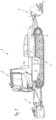
- a snowcat 1 after the Fig. 1 and 2 has a chassis frame 2, on whose opposite longitudinal sides two drive sides of a tracked drive 3 are arranged.
- Each drive side of the tracked drive 3 has a revolving chain, a front tensioning wheel, several running wheels arranged in a row one behind the other in the longitudinal direction of the vehicle, and a drive wheel 4 at the rear, also referred to as a sprocket wheel.
- the chain is deflected in the area of the front tensioning wheel and the rear sprocket wheel 4 and runs with an upper run above the running wheels and a lower run below the running wheels.
- the rear implement carrier carries a rear tiller 7.
- the rear tiller 7 is equipped with at least one rotatable tiller shaft and a finisher assembly that smooths the snow surface crushed and thrown up by the tiller shaft.
- a dozer blade 6 is hinged to a front end of the chassis frame 2.
- the dozer blade 6 is adjustable using hydraulic adjustment devices.
- a driver's cab 5 is located on the chassis frame 2 in the front half of the chassis frame 2, in which a driver sits to control the snow groomer 1 with regard to its driving and working functions.
- the driver's cab 5 is accessible for service work from the Fig. 1 shown operating position into a service position can be tilted forward about a tilting axis extending in the transverse direction of the vehicle, which pivots the driver's cab 5 on the chassis frame 2 in a tiltable manner.
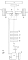
- the snow groomer 1 has a working hydraulic system that controls a hydrostatic milling motor 14 for the milling shaft of the rear tiller 7 as well as various hydraulic working and operating functions of the snow groomer 1.
- a hydrostatic brake pump 18 for the milling shaft of the rear tiller 7 as well as various hydraulic working and operating functions of the snow groomer 1.
- a hydrostatic brake pump 18 for the milling shaft of the rear tiller 7 as well as various hydraulic working and operating functions of the snow groomer 1.
- a hydrostatic brake pump 18 a hydrostatic working pump 17, and a hydrostatic fan pump 16 are provided, which supply hydraulic working and operating functions of the snow groomer 1.
- a hydrostatic milling pump 15 is assigned to the hydrostatic milling motor 14, which is hydraulic pressure for the hydrostatic milling motor 14.
- the aforementioned hydrostatic pumps 15 to 18 are driven coaxially by a drive shaft of an electric motor 8.
- the working pump 17 serves to build up hydrostatic pressure for linear actuators for adjusting the clearing blade and/or linear actuators for adjusting the rear implement carrier.
- the fan pump 16 serves to generate hydrostatic pressure for operating a hydrostatic rotary drive for a fan wheel or similar for ventilating and cooling electrical functional units of the snow groomer 1, which are described in more detail below.
- the brake pump 18, the working pump 17, the fan pump 16, the milling pump 15 and the hydrostatic milling motor 14 are parts of the working hydraulic system of the snow groomer 1.
- a drive system for the snow groomer 1 has two electric motors 11, which are designed as wheel hub motors, coaxial with each sprocket 4, each mechanically connected to the respective sprocket 4 by means of a planetary gear 13, in order to drive the sprocket.
- the two electric motors 11 are synchronous motors, each fed by a frequency converter 12 with direct current from a battery system 9 formed by a plurality of rechargeable accumulators.
- the battery system 9 is housed in the chassis frame 2 below the driver's cab 5 and is detachably fastened there to allow the battery system 9 to be replaced.
- the battery system 9 is positioned below the driver's cab 5 relative to the chassis frame 2 in such a way that the battery system 9 is accessible from above when the driver's cab 5 is in the tilted service position for removal. This allows the battery system 9 to be easily replaced with a new battery system.
- the working hydraulic system is driven by an electric motor 8, which rotates the various pump units and thereby generates the desired hydrostatic pressure.
- the various pump units are arranged coaxially with a drive shaft of the electric motor 8 to enable simple drive transmission.
- the electric motor 8 is also designed as a synchronous motor and is powered by the battery system 9.
- a frequency converter 19 is also used in the electric motor 8 to convert the direct current from the battery system 9 into the alternating current required for the synchronous motor of the electric motor 8.
- Both the electric motor 8 and the two electric motors 11 are operated with an operating voltage of 100 V.
- An electronic control unit S is assigned to the electric motors 8 and 11 and the battery system 9, which control the electric motors 8, 11 and includes a battery management system that ensures uniform utilization of the plurality of accumulators within the battery system 9.
- a brake chopper 20 assigned to the battery system 9 can absorb electrical energy that can no longer be absorbed by the battery system 9, particularly when the snowcat 1 is traveling downhill and a corresponding energy recovery is required.
- a charger 10 is permanently connected to the battery system 9 and is fixed to the vehicle on a rear wall of the driver's cab 5.
- the charger 10 is equipped with a voltage converter to enable charging of the battery system 9, which has a battery voltage of 100 V, from a building-side 380 V power grid.
- the snow groomer 1 therefore has a purely electric drive system, with the two electric motors 11 acting directly on the sprockets 4 on both sides of the tracked drive 3. Furthermore, the snow groomer 1 has hydrostatic drives for the rear tiller 7 on the one hand and various working and operating functions of the snow groomer 1 on the other, which are driven by a common electric motor 8.
- a snowcat according to Fig. 3 corresponds in structure and function to the snowcat, except for the differences listed below, as previously described with the help of the Fig. 1 and 2
- functionally identical parts and components are provided with the same reference symbols with the addition of the letter a.
- structurally and functionally identical components as well as with regard to the basic structure and function of the snow groomer, reference is made to the Fig. 1 and 2 described embodiment.
- the power supply for the various electric motors of the snowcat is provided in the high-voltage range with an operating voltage of 380 V/400 V.
- the battery system 9a is formed by several battery packs B 1 to B 3.
- the battery packs B 1 to B 3 are electrically connected to each other by an electrical circuit SB.
- the electrical circuit SB is housed in a closed housing.
- Both a charger 21 and a charging plug 22 are connected to the electrical circuit SB, with the charging plug 22 being connected to the charger via a flexible charging cable.
- the charging plug 22 can be plugged into a socket of a stationary power supply network if required.
- the battery system 9a is connected to a charging device 21 in accordance with the embodiment according to Fig. 2 an electronic control unit S, which includes a battery management system.
- the battery packs B 1 and B 2 are equipped with four batteries
- the battery pack B 3 is equipped with eight batteries.
- the corresponding vehicle electrical system includes a high-voltage distributor 24.
- the electric motor 8a which operates the working hydraulic system, is connected to the high-voltage distributor 24 via a frequency converter 19a.
- the working hydraulic system includes a hydrostatic brake pump 18, a hydrostatic working pump 17, and a hydrostatic fan pump 16, whose functions correspond to those previously described using the Fig. 1 and 2 functions already described.
- an electric motor 26 for driving at least one tiller shaft of the rear tiller 7a is mounted directly on the rear tiller 7a, so that the power supply to this electric motor 26 is also provided via a frequency converter 25 using the battery system operated in the high-voltage range described above.
- the electric motor 26 for the rear tiller 7a is connected to the high-voltage distributor 24 via its frequency converter 25 via an electrical line. Since the rear tiller 7a is detachably arranged on a rear implement carrier of the snow groomer, a high-voltage plug connection 23 is provided in the area of the implement carrier to connect the electric motor 26 for the rear tiller 7a to the vehicle's electrical system.
- the high-voltage connector 23 has two complementary and pluggable connector parts, one of which is connected to the electric motor 26 via a flexible cable, and the other to the vehicle's electrical system.
- the latter connector part is permanently arranged in the area of the implement carrier.
- the electric drive units 11 to 13 for the two sprockets 4 of the track drive do not differ from the design according to the Fig. 1 and 2 , so there is no need to go into this in more detail here.
Landscapes
- Engineering & Computer Science (AREA)
- Transportation (AREA)
- Mechanical Engineering (AREA)
- Power Engineering (AREA)
- Combustion & Propulsion (AREA)
- Chemical & Material Sciences (AREA)
- Structural Engineering (AREA)
- Life Sciences & Earth Sciences (AREA)
- Sustainable Development (AREA)
- Sustainable Energy (AREA)
- Civil Engineering (AREA)
- Architecture (AREA)
- Arrangement Or Mounting Of Propulsion Units For Vehicles (AREA)
- Electric Propulsion And Braking For Vehicles (AREA)
- Motor Power Transmission Devices (AREA)
Claims (10)
- Dameuse (1) avec un train de roulement à chenilles (3) qui est entraînable au moyen d'un système d'entraînement, sachant que le système d'entraînement présente deux moteurs électriques (11) qui sont associés respectivement à un barbotin (4) d'un côté du train de roulement à chenilles (3), caractérisé en qu'est prévu un système hydraulique de travail qui présente au moins un entraînement rotatif hydrostatique associé à une fonction de travail de la dameuse, sachant que le système hydraulique de travail présente un moteur de fraisage (14) conçu comme entraînement rotatif hydrostatique pour un arbre de fraisage d'une fraiseuse arrière (7) et une pompe de freinage (18) hydrostatique, une pompe de travail (17) hydrostatique et une pompe de ventilateur (16) hydrostatique, sachant qu'est associée au moteur de fraisage (14) une pompe de fraisage hydrostatique (15) qui applique une pression hydraulique pour le moteur de fraisage (14), sachant que la pompe de travail (17) sert à établir une pression hydrostatique pour des actionneurs linéaires destinés à régler la lame de dégagement et/ou pour des actionneurs linéaires destinés à régler un support d'outil arrière, sachant que la pompe de ventilateur (16) sert à générer une pression hydrostatique pour l'exploitation d'un entraînement rotatif hydrostatique pour une turbine de ventilateur destinée à ventiler et refroidir des unités fonctionnelles électriques de la dameuse (1), et que le système hydraulique de travail est entraîné par au moins un moteur électrique (8, 8a) qui est alimenté par une source d'énergie montée côté véhicule, et que la pompe de fraisage (15) hydrostatique, la pompe de ventilateur (16) hydrostatique, la pompe de travail (17) hydrostatique et la pompe de freinage (18) hydrostatique sont entraînées coaxialement par un arbre d'entraînement du moteur électrique (8).
- Dameuse selon la revendication 1, caractérisée en ce qu'un système de batteries (9, 9a) rechargeable est prévu pour l'alimentation électrique dudit au moins un moteur électrique (8, 8a, 11).
- Dameuse selon la revendication 2, caractérisée en ce que le moteur électrique (8, 8a) pour le système hydraulique de travail est conçu comme moteur synchrone et est alimenté - en service - sous une tension de batterie de 400 V ou 100 V.
- Dameuse selon la revendication 1 ou 2, caractérisée en ce que les moteurs électriques (11) du système d'entraînement sont conçus comme moteurs synchrones et sont alimentés - en service - sous une tension de batterie de 400 V ou 100 V.
- Dameuse selon l'une des revendications précédentes, caractérisée en ce qu'un dispositif de recharge (10, 21), notamment avec une fiche de recharge (22), est prévu côté véhicule.
- Dameuse selon la revendication 5, caractérisée en ce que le dispositif de recharge (10) est prévu avec un transformateur de tension.
- Dameuse selon la revendication 5 ou 6, caractérisée en ce que le dispositif de recharge (10, 21) et la fiche de recharge (22) sont installés au niveau d'une paroi arrière d'un poste de conduite (5).
- Dameuse selon la revendication 2 ou 3, caractérisée en ce que le système de batteries (9, 9a) est logé dans un cadre de train de roulement (2) sous le poste de conduite (5), de manière à être remplaçable.
- Dameuse selon la revendication 2 ou 3, caractérisée en ce que le système de batteries (9a) présente plusieurs blocs de batteries (B1 à B3) qui sont reliés entre eux respectivement au moyen d'une liaison enfichable (23) électrique de manière à être vite remplacés et sont reliés audit au moins un moteur électrique (26).
- Dameuse selon la revendication 9, caractérisée en ce qu'est associé aux blocs de batteries (B1 à B3) un circuit électrique (SB) qui couple électriquement les blocs de batteries (B1 à B3) entre eux ainsi qu'à d'autres composants électriques ou électroniques du système électrique du véhicule et notamment aux moteurs électriques (8a, 11, 26).
Priority Applications (3)
| Application Number | Priority Date | Filing Date | Title |
|---|---|---|---|
| EP25193073.1A EP4636161A3 (fr) | 2018-08-07 | 2019-07-04 | Dameuse avec une fraise arrière et un entraînement à chenilles |
| EP24207386.4A EP4470889A3 (fr) | 2018-08-07 | 2019-07-04 | Dameuse avec une fraise arrière et un entraînement à chenilles |
| EP24207387.2A EP4516560A1 (fr) | 2018-08-07 | 2019-07-04 | Dameuse avec un treuil et un entraînement à chaîne |
Applications Claiming Priority (1)
| Application Number | Priority Date | Filing Date | Title |
|---|---|---|---|
| DE102018213240.2A DE102018213240A1 (de) | 2018-08-07 | 2018-08-07 | Pistenraupe mit einem Kettenlaufwerk |
Related Child Applications (5)
| Application Number | Title | Priority Date | Filing Date |
|---|---|---|---|
| EP24207387.2A Division-Into EP4516560A1 (fr) | 2018-08-07 | 2019-07-04 | Dameuse avec un treuil et un entraînement à chaîne |
| EP24207387.2A Division EP4516560A1 (fr) | 2018-08-07 | 2019-07-04 | Dameuse avec un treuil et un entraînement à chaîne |
| EP25193073.1A Division EP4636161A3 (fr) | 2018-08-07 | 2019-07-04 | Dameuse avec une fraise arrière et un entraînement à chenilles |
| EP24207386.4A Division-Into EP4470889A3 (fr) | 2018-08-07 | 2019-07-04 | Dameuse avec une fraise arrière et un entraînement à chenilles |
| EP24207386.4A Division EP4470889A3 (fr) | 2018-08-07 | 2019-07-04 | Dameuse avec une fraise arrière et un entraînement à chenilles |
Publications (2)
| Publication Number | Publication Date |
|---|---|
| EP3608151A1 EP3608151A1 (fr) | 2020-02-12 |
| EP3608151B1 true EP3608151B1 (fr) | 2025-04-16 |
Family
ID=67180585
Family Applications (4)
| Application Number | Title | Priority Date | Filing Date |
|---|---|---|---|
| EP24207387.2A Pending EP4516560A1 (fr) | 2018-08-07 | 2019-07-04 | Dameuse avec un treuil et un entraînement à chaîne |
| EP19184295.4A Active EP3608151B1 (fr) | 2018-08-07 | 2019-07-04 | Engin de damage de pistes doté d'un train de roulement à chenille |
| EP24207386.4A Pending EP4470889A3 (fr) | 2018-08-07 | 2019-07-04 | Dameuse avec une fraise arrière et un entraînement à chenilles |
| EP25193073.1A Pending EP4636161A3 (fr) | 2018-08-07 | 2019-07-04 | Dameuse avec une fraise arrière et un entraînement à chenilles |
Family Applications Before (1)
| Application Number | Title | Priority Date | Filing Date |
|---|---|---|---|
| EP24207387.2A Pending EP4516560A1 (fr) | 2018-08-07 | 2019-07-04 | Dameuse avec un treuil et un entraînement à chaîne |
Family Applications After (2)
| Application Number | Title | Priority Date | Filing Date |
|---|---|---|---|
| EP24207386.4A Pending EP4470889A3 (fr) | 2018-08-07 | 2019-07-04 | Dameuse avec une fraise arrière et un entraînement à chenilles |
| EP25193073.1A Pending EP4636161A3 (fr) | 2018-08-07 | 2019-07-04 | Dameuse avec une fraise arrière et un entraînement à chenilles |
Country Status (2)
| Country | Link |
|---|---|
| EP (4) | EP4516560A1 (fr) |
| DE (1) | DE102018213240A1 (fr) |
Families Citing this family (3)
| Publication number | Priority date | Publication date | Assignee | Title |
|---|---|---|---|---|
| DE102021200268A1 (de) | 2021-01-13 | 2022-07-14 | Kässbohrer Geländefahrzeug Aktiengesellschaft | Pistenpflegefahrzeug |
| DE102021202819A1 (de) * | 2021-03-23 | 2022-09-29 | Kässbohrer Geländefahrzeug Aktiengesellschaft | Pistenraupe und Verfahren zum Steuern der Stromversorgung einer Pistenraupe |
| DE102022203857A1 (de) | 2022-04-20 | 2023-10-26 | Kässbohrer Geländefahrzeug Aktiengesellschaft | Pistenraupe zur Gestaltung und Pflege von Schneegelände |
Citations (1)
| Publication number | Priority date | Publication date | Assignee | Title |
|---|---|---|---|---|
| EP1245736A2 (fr) * | 2001-03-30 | 2002-10-02 | Prinoth GmbH-S.r.l. | Appareil pour l'entretien des pistes de ski avec fraiseuse montée de façon pivotante |
Family Cites Families (9)
| Publication number | Priority date | Publication date | Assignee | Title |
|---|---|---|---|---|
| US5363937A (en) | 1992-10-19 | 1994-11-15 | Lmc Operating Corp. | Battery operated tracked vehicle |
| DE29607651U1 (de) * | 1996-04-26 | 1997-08-28 | Kässbohrer Geländefahrzeug AG, 89250 Senden | Kettenfahrzeug |
| DE10333594A1 (de) * | 2003-07-24 | 2005-02-17 | Linde Ag | Batteriewechsel-System für ein batterie-elektrisch betriebenes Flurförderzeug |
| DE102009047065A1 (de) * | 2009-11-24 | 2011-05-26 | SB LiMotive Company Ltd., Suwon | Serienschaltung von Schaltreglern zur Energieübertragung in Batteriesystemen |
| DE102010049984A1 (de) * | 2010-10-19 | 2012-04-19 | Kässbohrer Geländefahrzeug AG | Verfahren zur Steuerung einer Seilwinde eines Kettenfahrzeugs und Pistenraupe |
| DE102010043511A1 (de) * | 2010-11-05 | 2012-05-10 | Kässbohrer Geländefahrzeug AG | Pistenraupe |
| DE102011087711A1 (de) * | 2011-12-05 | 2013-06-06 | Zf Friedrichshafen Ag | Hybrid- oder Elektrofahrzeug |
| DE202013004087U1 (de) * | 2012-05-29 | 2013-05-27 | Kässbohrer Geländefahrzeug AG | Pistenraupe |
| CN111942326A (zh) * | 2013-12-11 | 2020-11-17 | 普瑞诺斯有限公司 | 雪道整理机或其它履带式车辆及其系统 |
-
2018
- 2018-08-07 DE DE102018213240.2A patent/DE102018213240A1/de active Pending
-
2019
- 2019-07-04 EP EP24207387.2A patent/EP4516560A1/fr active Pending
- 2019-07-04 EP EP19184295.4A patent/EP3608151B1/fr active Active
- 2019-07-04 EP EP24207386.4A patent/EP4470889A3/fr active Pending
- 2019-07-04 EP EP25193073.1A patent/EP4636161A3/fr active Pending
Patent Citations (1)
| Publication number | Priority date | Publication date | Assignee | Title |
|---|---|---|---|---|
| EP1245736A2 (fr) * | 2001-03-30 | 2002-10-02 | Prinoth GmbH-S.r.l. | Appareil pour l'entretien des pistes de ski avec fraiseuse montée de façon pivotante |
Also Published As
| Publication number | Publication date |
|---|---|
| EP4636161A2 (fr) | 2025-10-22 |
| DE102018213240A1 (de) | 2020-02-13 |
| EP3608151A1 (fr) | 2020-02-12 |
| EP4636161A3 (fr) | 2025-11-12 |
| EP4516560A1 (fr) | 2025-03-05 |
| EP4470889A2 (fr) | 2024-12-04 |
| EP4470889A3 (fr) | 2025-03-05 |
Similar Documents
| Publication | Publication Date | Title |
|---|---|---|
| EP3608151B1 (fr) | Engin de damage de pistes doté d'un train de roulement à chenille | |
| EP0895495B1 (fr) | Vehicule sur chenilles pour l'entretien de pistes | |
| DE102010010578B4 (de) | Hydrostatisch-elektrischer Antrieb, Flurförderfahrzeug mit einem solchen Antrieb | |
| DE202014000738U1 (de) | Radlader mit Energiespeichereinheit | |
| DE112012001408T5 (de) | Elektroarbeitsfahrzeug und Batteriehaltekonstruktion desselben | |
| DE60031545T2 (de) | Schaufel | |
| EP0628661B1 (fr) | Finisseur | |
| EP0489969A1 (fr) | Finisseuse | |
| DE102014011195B4 (de) | Bodenfräsmaschine mit von einem Wartungsmotor betriebenem Kompressor und Verfahren zum Betrieb einer solchen Bodenfräsmaschine | |
| EP4491433A2 (fr) | Engin de damage de pistes doté d'un train de roulement à chenille | |
| EP0826581A1 (fr) | Véhicule orientable pour le transport d'un excavateur à chenilles | |
| DE202020107068U1 (de) | Arbeitsfahrzeug | |
| EP4396013B1 (fr) | Ensemble chaîne de puissance d'un engin de travail et engin de travail | |
| DE202013004087U1 (de) | Pistenraupe | |
| DE102012212248A1 (de) | Kettenfahrzeug mit einem zentralen Antriebsmotor | |
| DE102004018588B4 (de) | Arbeitsmaschine mit Eigenantrieb zum Hinterhergehen | |
| EP1118714B2 (fr) | Finisseuse | |
| EP4344926B1 (fr) | Machine de travail dotée d'un entraînement électrique | |
| DE2602898A1 (de) | Universal-arbeitsmaschine | |
| EP3469872B1 (fr) | Appareil de travail, véhicule de travail doté d'un tel dispositif de travail, système modulaire de fabrication d'appareil de travail ainsi que procédé de fonctionnement d'au moins l'appareil de travail | |
| EP1391370A1 (fr) | Véhicule de travail dirigeable automoteur | |
| EP4269151A1 (fr) | Dameuse pour la conception et l'entretien de terrain enneigés | |
| EP4360421A2 (fr) | Outil | |
| DE102024112891A1 (de) | Mobile Arbeitsmaschine mit Energiespeichereinheit und Ladeanschluss | |
| DE102024117762A1 (de) | Mobilisiereinrichtung |
Legal Events
| Date | Code | Title | Description |
|---|---|---|---|
| PUAI | Public reference made under article 153(3) epc to a published international application that has entered the european phase |
Free format text: ORIGINAL CODE: 0009012 |
|
| STAA | Information on the status of an ep patent application or granted ep patent |
Free format text: STATUS: THE APPLICATION HAS BEEN PUBLISHED |
|
| AK | Designated contracting states |
Kind code of ref document: A1 Designated state(s): AL AT BE BG CH CY CZ DE DK EE ES FI FR GB GR HR HU IE IS IT LI LT LU LV MC MK MT NL NO PL PT RO RS SE SI SK SM TR |
|
| AX | Request for extension of the european patent |
Extension state: BA ME |
|
| STAA | Information on the status of an ep patent application or granted ep patent |
Free format text: STATUS: REQUEST FOR EXAMINATION WAS MADE |
|
| 17P | Request for examination filed |
Effective date: 20200708 |
|
| RBV | Designated contracting states (corrected) |
Designated state(s): AL AT BE BG CH CY CZ DE DK EE ES FI FR GB GR HR HU IE IS IT LI LT LU LV MC MK MT NL NO PL PT RO RS SE SI SK SM TR |
|
| STAA | Information on the status of an ep patent application or granted ep patent |
Free format text: STATUS: EXAMINATION IS IN PROGRESS |
|
| 17Q | First examination report despatched |
Effective date: 20210922 |
|
| GRAP | Despatch of communication of intention to grant a patent |
Free format text: ORIGINAL CODE: EPIDOSNIGR1 |
|
| STAA | Information on the status of an ep patent application or granted ep patent |
Free format text: STATUS: GRANT OF PATENT IS INTENDED |
|
| INTG | Intention to grant announced |
Effective date: 20241223 |
|
| GRAS | Grant fee paid |
Free format text: ORIGINAL CODE: EPIDOSNIGR3 |
|
| GRAA | (expected) grant |
Free format text: ORIGINAL CODE: 0009210 |
|
| STAA | Information on the status of an ep patent application or granted ep patent |
Free format text: STATUS: THE PATENT HAS BEEN GRANTED |
|
| AK | Designated contracting states |
Kind code of ref document: B1 Designated state(s): AL AT BE BG CH CY CZ DE DK EE ES FI FR GB GR HR HU IE IS IT LI LT LU LV MC MK MT NL NO PL PT RO RS SE SI SK SM TR |
|
| REG | Reference to a national code |
Ref country code: GB Ref legal event code: FG4D Free format text: NOT ENGLISH |
|
| P01 | Opt-out of the competence of the unified patent court (upc) registered |
Free format text: CASE NUMBER: APP_14063/2025 Effective date: 20250321 |
|
| REG | Reference to a national code |
Ref country code: CH Ref legal event code: EP Ref country code: DE Ref legal event code: R096 Ref document number: 502019013205 Country of ref document: DE |
|
| REG | Reference to a national code |
Ref country code: IE Ref legal event code: FG4D Free format text: LANGUAGE OF EP DOCUMENT: GERMAN |
|
| REG | Reference to a national code |
Ref country code: NL Ref legal event code: MP Effective date: 20250416 |
|
| PG25 | Lapsed in a contracting state [announced via postgrant information from national office to epo] |
Ref country code: NL Free format text: LAPSE BECAUSE OF FAILURE TO SUBMIT A TRANSLATION OF THE DESCRIPTION OR TO PAY THE FEE WITHIN THE PRESCRIBED TIME-LIMIT Effective date: 20250416 |
|
| PG25 | Lapsed in a contracting state [announced via postgrant information from national office to epo] |
Ref country code: PT Free format text: LAPSE BECAUSE OF FAILURE TO SUBMIT A TRANSLATION OF THE DESCRIPTION OR TO PAY THE FEE WITHIN THE PRESCRIBED TIME-LIMIT Effective date: 20250818 Ref country code: ES Free format text: LAPSE BECAUSE OF FAILURE TO SUBMIT A TRANSLATION OF THE DESCRIPTION OR TO PAY THE FEE WITHIN THE PRESCRIBED TIME-LIMIT Effective date: 20250416 Ref country code: FI Free format text: LAPSE BECAUSE OF FAILURE TO SUBMIT A TRANSLATION OF THE DESCRIPTION OR TO PAY THE FEE WITHIN THE PRESCRIBED TIME-LIMIT Effective date: 20250416 |
|
| PGFP | Annual fee paid to national office [announced via postgrant information from national office to epo] |
Ref country code: DE Payment date: 20250723 Year of fee payment: 7 |
|
| REG | Reference to a national code |
Ref country code: LT Ref legal event code: MG9D |
|
| PG25 | Lapsed in a contracting state [announced via postgrant information from national office to epo] |
Ref country code: NO Free format text: LAPSE BECAUSE OF FAILURE TO SUBMIT A TRANSLATION OF THE DESCRIPTION OR TO PAY THE FEE WITHIN THE PRESCRIBED TIME-LIMIT Effective date: 20250716 Ref country code: GR Free format text: LAPSE BECAUSE OF FAILURE TO SUBMIT A TRANSLATION OF THE DESCRIPTION OR TO PAY THE FEE WITHIN THE PRESCRIBED TIME-LIMIT Effective date: 20250717 |
|
| PG25 | Lapsed in a contracting state [announced via postgrant information from national office to epo] |
Ref country code: PL Free format text: LAPSE BECAUSE OF FAILURE TO SUBMIT A TRANSLATION OF THE DESCRIPTION OR TO PAY THE FEE WITHIN THE PRESCRIBED TIME-LIMIT Effective date: 20250416 |
|
| PGFP | Annual fee paid to national office [announced via postgrant information from national office to epo] |
Ref country code: IT Payment date: 20250808 Year of fee payment: 7 |
|
| PG25 | Lapsed in a contracting state [announced via postgrant information from national office to epo] |
Ref country code: BG Free format text: LAPSE BECAUSE OF FAILURE TO SUBMIT A TRANSLATION OF THE DESCRIPTION OR TO PAY THE FEE WITHIN THE PRESCRIBED TIME-LIMIT Effective date: 20250416 |
|
| PG25 | Lapsed in a contracting state [announced via postgrant information from national office to epo] |
Ref country code: HR Free format text: LAPSE BECAUSE OF FAILURE TO SUBMIT A TRANSLATION OF THE DESCRIPTION OR TO PAY THE FEE WITHIN THE PRESCRIBED TIME-LIMIT Effective date: 20250416 |
|
| PGFP | Annual fee paid to national office [announced via postgrant information from national office to epo] |
Ref country code: FR Payment date: 20250723 Year of fee payment: 7 Ref country code: AT Payment date: 20250721 Year of fee payment: 7 |
|
| PGFP | Annual fee paid to national office [announced via postgrant information from national office to epo] |
Ref country code: CH Payment date: 20250801 Year of fee payment: 7 |
|
| PG25 | Lapsed in a contracting state [announced via postgrant information from national office to epo] |
Ref country code: RS Free format text: LAPSE BECAUSE OF FAILURE TO SUBMIT A TRANSLATION OF THE DESCRIPTION OR TO PAY THE FEE WITHIN THE PRESCRIBED TIME-LIMIT Effective date: 20250716 |
|
| PG25 | Lapsed in a contracting state [announced via postgrant information from national office to epo] |
Ref country code: IS Free format text: LAPSE BECAUSE OF FAILURE TO SUBMIT A TRANSLATION OF THE DESCRIPTION OR TO PAY THE FEE WITHIN THE PRESCRIBED TIME-LIMIT Effective date: 20250816 |
|
| PG25 | Lapsed in a contracting state [announced via postgrant information from national office to epo] |
Ref country code: LV Free format text: LAPSE BECAUSE OF FAILURE TO SUBMIT A TRANSLATION OF THE DESCRIPTION OR TO PAY THE FEE WITHIN THE PRESCRIBED TIME-LIMIT Effective date: 20250416 |
|
| PG25 | Lapsed in a contracting state [announced via postgrant information from national office to epo] |
Ref country code: SM Free format text: LAPSE BECAUSE OF FAILURE TO SUBMIT A TRANSLATION OF THE DESCRIPTION OR TO PAY THE FEE WITHIN THE PRESCRIBED TIME-LIMIT Effective date: 20250416 Ref country code: DK Free format text: LAPSE BECAUSE OF FAILURE TO SUBMIT A TRANSLATION OF THE DESCRIPTION OR TO PAY THE FEE WITHIN THE PRESCRIBED TIME-LIMIT Effective date: 20250416 |
|
| REG | Reference to a national code |
Ref country code: DE Ref legal event code: R097 Ref document number: 502019013205 Country of ref document: DE |
|
| PG25 | Lapsed in a contracting state [announced via postgrant information from national office to epo] |
Ref country code: CZ Free format text: LAPSE BECAUSE OF FAILURE TO SUBMIT A TRANSLATION OF THE DESCRIPTION OR TO PAY THE FEE WITHIN THE PRESCRIBED TIME-LIMIT Effective date: 20250416 |
|
| PG25 | Lapsed in a contracting state [announced via postgrant information from national office to epo] |
Ref country code: EE Free format text: LAPSE BECAUSE OF FAILURE TO SUBMIT A TRANSLATION OF THE DESCRIPTION OR TO PAY THE FEE WITHIN THE PRESCRIBED TIME-LIMIT Effective date: 20250416 |
|
| PG25 | Lapsed in a contracting state [announced via postgrant information from national office to epo] |
Ref country code: RO Free format text: LAPSE BECAUSE OF FAILURE TO SUBMIT A TRANSLATION OF THE DESCRIPTION OR TO PAY THE FEE WITHIN THE PRESCRIBED TIME-LIMIT Effective date: 20250416 Ref country code: SK Free format text: LAPSE BECAUSE OF FAILURE TO SUBMIT A TRANSLATION OF THE DESCRIPTION OR TO PAY THE FEE WITHIN THE PRESCRIBED TIME-LIMIT Effective date: 20250416 |
|
| PLBE | No opposition filed within time limit |
Free format text: ORIGINAL CODE: 0009261 |
|
| STAA | Information on the status of an ep patent application or granted ep patent |
Free format text: STATUS: NO OPPOSITION FILED WITHIN TIME LIMIT |
|
| REG | Reference to a national code |
Ref country code: CH Ref legal event code: L10 Free format text: ST27 STATUS EVENT CODE: U-0-0-L10-L00 (AS PROVIDED BY THE NATIONAL OFFICE) Effective date: 20260225 |
|
| PG25 | Lapsed in a contracting state [announced via postgrant information from national office to epo] |
Ref country code: LU Free format text: LAPSE BECAUSE OF NON-PAYMENT OF DUE FEES Effective date: 20250704 |
|
| 26N | No opposition filed |
Effective date: 20260119 |
|
| GBPC | Gb: european patent ceased through non-payment of renewal fee |
Effective date: 20250716 |
|
| REG | Reference to a national code |
Ref country code: BE Ref legal event code: MM Effective date: 20250731 |
|
| PG25 | Lapsed in a contracting state [announced via postgrant information from national office to epo] |
Ref country code: GB Free format text: LAPSE BECAUSE OF NON-PAYMENT OF DUE FEES Effective date: 20250716 |
|
| PG25 | Lapsed in a contracting state [announced via postgrant information from national office to epo] |
Ref country code: BE Free format text: LAPSE BECAUSE OF NON-PAYMENT OF DUE FEES Effective date: 20250731 |