EP4345032A2 - Dispositif de transport de palettes - Google Patents
Dispositif de transport de palettes Download PDFInfo
- Publication number
- EP4345032A2 EP4345032A2 EP23212592.2A EP23212592A EP4345032A2 EP 4345032 A2 EP4345032 A2 EP 4345032A2 EP 23212592 A EP23212592 A EP 23212592A EP 4345032 A2 EP4345032 A2 EP 4345032A2
- Authority
- EP
- European Patent Office
- Prior art keywords
- units
- pallet
- lifting
- transport device
- wheel units
- Prior art date
- Legal status (The legal status is an assumption and is not a legal conclusion. Google has not performed a legal analysis and makes no representation as to the accuracy of the status listed.)
- Pending
Links
Images

















Classifications
-
- B—PERFORMING OPERATIONS; TRANSPORTING
- B65—CONVEYING; PACKING; STORING; HANDLING THIN OR FILAMENTARY MATERIAL
- B65G—TRANSPORT OR STORAGE DEVICES, e.g. CONVEYORS FOR LOADING OR TIPPING, SHOP CONVEYOR SYSTEMS OR PNEUMATIC TUBE CONVEYORS
- B65G1/00—Storing articles, individually or in orderly arrangement, in warehouses or magazines
- B65G1/02—Storage devices
- B65G1/04—Storage devices mechanical
- B65G1/0492—Storage devices mechanical with cars adapted to travel in storage aisles
-
- B—PERFORMING OPERATIONS; TRANSPORTING
- B65—CONVEYING; PACKING; STORING; HANDLING THIN OR FILAMENTARY MATERIAL
- B65G—TRANSPORT OR STORAGE DEVICES, e.g. CONVEYORS FOR LOADING OR TIPPING, SHOP CONVEYOR SYSTEMS OR PNEUMATIC TUBE CONVEYORS
- B65G2201/00—Indexing codes relating to handling devices, e.g. conveyors, characterised by the type of product or load being conveyed or handled
- B65G2201/02—Articles
- B65G2201/0267—Pallets
-
- B—PERFORMING OPERATIONS; TRANSPORTING
- B65—CONVEYING; PACKING; STORING; HANDLING THIN OR FILAMENTARY MATERIAL
- B65G—TRANSPORT OR STORAGE DEVICES, e.g. CONVEYORS FOR LOADING OR TIPPING, SHOP CONVEYOR SYSTEMS OR PNEUMATIC TUBE CONVEYORS
- B65G2203/00—Indexing code relating to control or detection of the articles or the load carriers during conveying
- B65G2203/02—Control or detection
- B65G2203/0266—Control or detection relating to the load carrier(s)
- B65G2203/0283—Position of the load carrier
-
- B—PERFORMING OPERATIONS; TRANSPORTING
- B65—CONVEYING; PACKING; STORING; HANDLING THIN OR FILAMENTARY MATERIAL
- B65G—TRANSPORT OR STORAGE DEVICES, e.g. CONVEYORS FOR LOADING OR TIPPING, SHOP CONVEYOR SYSTEMS OR PNEUMATIC TUBE CONVEYORS
- B65G2203/00—Indexing code relating to control or detection of the articles or the load carriers during conveying
- B65G2203/04—Detection means
- B65G2203/042—Sensors
- B65G2203/044—Optical
Definitions
- the present invention relates to a pallet transport device for transporting pallets within a shelf device aligned orthogonally with a longitudinal direction, a transverse direction and a height direction along a travel path with longitudinal transport paths in the x direction and transverse transport paths in the z direction, with a chassis with a pallet receiving unit, an x Chassis for the movement in the longitudinal direction with drivable left x-wheel units and right x-wheel units arranged laterally on the left and right spaced apart in the x direction, a z-carriage for the process in the transverse direction with drivable spaced left z-wheel units arranged laterally on the left and right and right z wheel units, travel drive units for the wheel units, whereby the x or z wheel units can be brought into contact with the travel path depending on the x or z direction of travel.
- Such pallet transport devices are also called pallet shuttles.
- High-bay warehouses for storing piece goods in a compressed manner, with the piece goods stored on pallets, are used in a variety of different geometries and usually have a number of shelves, which are preferably arranged in rows and into which piece goods can be stored or retrieved.
- Such high-bay warehouses are often operated by forklifts for storage and retrieval, with the forklifts moving in the aisles between the rows formed by the shelves.
- Such storage systems are their economic use is not optimal. Therefore, the aim is to automate such high-bay warehouses using loading and unloading systems that reliably enable the provision or collection of piece goods at predefined storage locations within the shelving system.
- a high-bay warehouse for storing pallets is described with a plurality of high-bay racks which are set up in rack aisles so that aisles are formed between the rack aisles, wherein storage channels are formed in the high-bay racks in which at least one pallet can be stored, wherein a so-called tandem shuttle is used which comprises an aisle carriage and a channel carriage, wherein the aisle carriage is designed to travel on an aisle rail area and the channel carriage is designed to travel on a channel rail area.
- the channel carriage is designed to transport a pallet in a channel rail area and the aisle carriage is designed to transport the channel carriage in an aisle rail area.
- a vertical transport device is used which enables the tandem shuttle to be transported from a first level to a second level.
- the change of direction is carried out in such a way that the pallet truck carries out a lifting and lowering movement of the chassis, whereby the pallet receiving unit must also be raised or lowered during this process.
- This requires a relatively high energy expenditure, since in order to change direction the pallet receiving unit and thus also the pallet stored on the pallet receiving unit with its weight must be raised or lowered.
- the additional lift also changes the approach dimension.
- the WO 2005/077789 A1 discloses an automated warehouse shelving system with pallet transport devices that are arranged within the warehouse so that they can move in the x and y directions. There is a set of wheels for each direction (x, z). The drive of the various wheel sets is controlled via two couplings.
- the shuttle has 3 configurations, namely driving in the aisle direction, driving in the pallet direction and lifting in the pallet direction. Cross travel in the z direction is only possible on special aisles. Completely variable travel on the level in the x and z directions is not possible. There is no control of straight-ahead travel; instead, lateral guide rollers and rails are used to keep the shuttle on its path.
- the drive and movement means for travel in the longitudinal and transverse directions x, z can be controlled separately.
- the US 3,978,995A discloses a storage facility with a pallet shuttle that only allows travel in the x direction, in which a mechanism lifts the pallets from the shelf, a change of direction is not possible and only simple deep storage within the shelving system is possible.
- the EP 2 308 778 A2 and EP 2 308 777 B1 disclose an automatic storage shuttle of the type mentioned above with an upper support surface that can carry a loading unit, a lifting device to raise/lower the upper support surface, four wheel assemblies, each arranged in the corner area of the shuttle and individually drivable, each via a drive unit.
- the wheels can be rotated by 90 ° so that a change of direction is possible. All four wheels are each driven individually via a corresponding drive unit.
- Sensors on the drive wheels record the respective wall distance to the surrounding components.
- a control device regulates the rotational speed or torque of the driven wheels depending on the signals received.
- the movement of the shuttle is possible by rotating the wheel assemblies by 90 ° in two vertical directions.
- a pallet shuttle in which wheel units are arranged in the corner area, each of which has its own drive unit and can be rotated in its drive direction in the x or z direction as required.
- the pallet receiving unit can be raised or lowered using a special mechanism.
- the present invention is based on the object or technical problem of specifying a pallet transport device of the type mentioned at the outset, which can be operated in an energy-efficient manner, can be produced economically, enables a change in direction of travel from the x to z direction with little design effort, and ensures long-term reliable function and a precise positioning of the pallet transport device within one Shelving system ensures in the x and z directions, has a compact structure and overall enables automatic and efficient storage of piece goods within a shelving device.
- the pallet transport device according to the invention according to claim 1 is therefore characterized in that the x-carriage/the x-wheel units and the z-carriage/the z-wheel units are designed to be vertically movable in the y direction, mechanically independently of one another, an x-lifting device for the movement of the x-carriage or the x-wheel units is present in the y-direction, a z-lifting device is present for the movement of the z-carriage or the z-wheel units in the y-direction, if necessary a y-lifting device is present for the movement of the pallet receiving unit is, the x / z lifting devices are designed to be activated independently of each other and independently of the y lifting device of the pallet receiving unit in the y direction.
- a particularly preferred embodiment is characterized in that a single lifting drive unit is present which activates the lifting movement of the x or z and/or the y lifting device or there is an x-lift drive unit and a z-lift drive unit for the x/z lifting device.
- the lifting devices are designed in such a way that a change in the direction of travel from the x- to the z-direction and vice versa takes place by corresponding lowering and raising of the respective x-/z-chassis or the respective x-/z-wheel units, without a simultaneous displacement of the pallet receiving unit via the y-lifting device in the height direction.
- a pallet transport device that is particularly easy to implement and controllable is characterized by the fact that the lifting devices, the chassis and the wheel units are designed in such a way that when the direction changes from the lowers the z-wheel units to the level of the x-carriage or the x-wheel units and then the x-lifting device raises the x-carriage or the x-wheel units without the height level of the pallet receiving unit changing and when changing direction from z- is reversed in the x direction.
- An advantageous embodiment which enables a lifting movement of the pallet receiving unit independently of the lifting movements of the chassis or wheel units, is characterized in that a y-lifting device is provided for the movement of the pallet receiving unit in the y-direction, and the y-lifting device is designed to be controllable independently of the x- and z-lifting device.
- each lifting device has at least one rotatable cam disk or at least one displaceable link disk to which the respective chassis or the respective wheel units and / or the pallet receiving unit are coupled, the geometry of the cam disks or link disks determining the size and the time course of the mechanically independent movement of the respective chassis/wheel units or pallet receiving unit in the y-direction.
- a particularly advantageous embodiment in the context of a compact structure is characterized in that all cam disks/slide disks for the chassis/wheel units or the pallet receiving unit are arranged on a rotatable shaft or on a sliding mechanism and the movement sequences for changing direction/stroke of the pallet receiving unit are related to one another in time coordinated stroke paths in the y-direction are stored in the geometry and the positional arrangement of the cam disks/slide disks, with the shaft or the displacement mechanism being activated via at least one lifting drive unit.
- the x-lifting device/z-lifting device can be moved via a drivable spindle device, in particular one that is rotatable on each side, which acts directly or indirectly on the x-chassis/z-chassis or the x-wheel units/z-wheel units and the spindle device can be controlled via a common lifting drive unit or via an x-lifting drive unit for the x-chassis/the x-wheel units and via a z-lifting drive unit for the z-chassis/the z-wheel units.
- the rotary movement of the drive unit(s) is preferably implemented constructively on the spindle device or on individual spindles via coupling devices, whereby the Coupling mechanism of the coupling devices can be designed, for example, as a simple lever mechanism, as a double lever mechanism, as a scissor mechanism, as a double scissor mechanism or particularly preferably as a toggle lever mechanism.
- a particularly advantageous further development according to the invention which can also be used independently of the above-described inventive design of a pallet transport device or in combination with the same, is characterized in that a first travel drive unit and a second travel drive unit are present, wherein each travel drive unit is directly or indirectly coupled in terms of drive to left x-wheel units or left z-wheel units and right x-wheel units or right z-wheel units of one side.
- an advantageous embodiment that is particularly easy to implement in terms of construction and which ensures long-term reliable function with a compact design at the same time is characterized in that the coupling device between the first and / or second travel drive unit to the wheel units has at least one angular gear, a cardan shaft and / or at least one toothed belt and / or at least one chain and / or at least one shaft unit and / or at least one omega drive and / or at least one thrust shaft unit.
- the coupling device is designed in such a way that it converts the drive of the x-wheel units or z-wheel units at different height levels in the y direction.
- a particularly advantageous embodiment is characterized in that the first and second travel drive unit each drives the associated x-wheel unit(s) or x-chassis directly and the associated z-wheel unit(s) or z-chassis indirectly via the coupling device, or vice versa.
- the pallet transport device can also be designed in such a way that the first and second travel drive units are each connected to the height-adjustable x- or z-chassis, i.e. are coupled in terms of movement to the chassis in the y-direction.
- a variant of the pallet transport device according to the invention is characterized in that the first and second travel drive units are stationary within the device.
- a particularly advantageous development which ensures a permanently reliable function with regard to the track guidance in the x or z direction, is characterized in that a mechanical guide profile device is arranged on a drive side in the x direction and/or on a drive side in the z direction, which is coupled to the x chassis and/or the z chassis, a first guide roller device with at least one first guide roller unit is present, two second guide roller devices with at least one second guide roller unit are arranged in the x or z direction in front of or behind the first guide roller device, wherein the guide roller units are designed to be freely rotatable about a y axis of rotation, wherein the first and second guide roller devices are designed such that they can be arranged between opposite flanges of an x/z travel path profile of a travel path that project in the y direction and the first guide roller units can be brought into contact with the inside of the first flange and the second guide roller units with the inside of the second flange, additionally in that the first and second guide roller units are designed as guide
- the pallet transport device is characterized in that a control device for controlling the drive of the first and second travel drive units and/or the lifting drive units is present and sensor units are present which detect the respective position of the pallet transport device within the shelving system and communicate accordingly with the control device.
- At least one first sensor unit is present, which detects route markings/position markings present on the travel path and emits corresponding signals to the control device for track control and/or for changing direction and/or for lifting the pallet receiving unit.
- the pallet transport device can be steered “like a tank” and any deviation in the direction of travel can be corrected at any time.
- the pallet transport device in such a way that two first sensor units are present, which are arranged diagonally opposite one another in the corner area or on one side of the device.
- a particularly advantageous embodiment which implements optimal sensor control for straight-ahead running and changing direction, is characterized in that two z-sensor units spaced apart in the z-direction are present on the underside of the pallet transport device, and two x-sensor units spaced apart in the x-direction are present on the underside of the pallet transport device Pallet transport device is present, a control device for the lifting unit and for the first and second travel drive units is present, the z and x sensor units measuring the distance to the inside of the underside z and x vehicle profiles forming the travel path and corresponding ones Send signals to the control device, whereby when traveling in the x or z direction, the control device calculates any angular deviation from straight-line stability based on the signals from the x sensor units or the z sensor units and controls the first/second travel drive unit accordingly to correct the angular deviation, whereby when changing the direction of travel from x to z direction or from z to x direction, the control device based on the signals from the x or z sensor units when
- a particularly advantageous development of the pallet transport device according to the invention is characterized in that further sensor units are present which communicate with the control device, and the for collision detection in the x and z directions and/or for detecting the storage space occupancy and/or for detecting the height level of the pallet receiving unit and/or for detecting the occupancy status of the pallet receiving unit.
- Sensor units can be used that are based on an optical, inductive, magnetic or mechanical operating principle.
- the three independent lifting devices for the x, z and y directions for the x and z chassis or x and z wheel units and the pallet receiving unit are clearly defined construction elements for the change of direction and the stroke of the pallet receiving unit.
- These independent lifting devices can be controlled in a special way with regard to their respective displacement path via cams or links, with the sequence program for the elements mentioned when changing the direction of travel or the movement of the pallet receiving unit being stored in the cam/link geometry and the arrangement of the cams/links relative to one another and can be accessed mechanically in a permanently reliable manner.
- the control of the sequence program is preferably carried out via one or, if necessary, two drive motors.
- a lifting movement of the pallet receiving unit is also possible when traveling in the z-direction, which is possible, for example, in the context of an application within the front zone of the racking system, i.e. in the area in which no travel paths in the x and z directions are specified.
- the pallet transport devices can also be used for driving in the front zone of the racking system, whereby active changes of direction in the front zone can be easily implemented by changing the chassis or wheel sets or by different speeds of the wheel units (tracked vehicle principle).
- a change of direction without a stroke of the pallet receiving unit, travel in two directions (x and z direction) and also control of straight running can be easily implemented in a particularly advantageous manner based on a compact overall construction while ensuring a permanently reliable function become.
- Simple and permanently reliable mechanical designs can be easily implemented for coupling the lifting drive units to the lifting devices and the travel drive units to the chassis or wheel units.
- the pallet transport device according to the invention is characterized in that it consumes less energy than the known devices and the components are subject to little wear. Furthermore, the pallet transport device according to the invention is significantly lower than comparable known solutions with travel in the x and z directions.
- the pallet transport device enables not only a movement in the orthogonal x- or z-direction but also a curve travel, which can be used advantageously, for example, in the front zone of the racking system - without the specification of orthogonal travel paths.
- a so-called tank drive is implemented, since opposite Wheel sides can be controlled differently by the two independent drive units.
- FIG. 1 and 2 A first embodiment of a pallet transport device 10 is shown in a highly schematic manner, which is used to transport pallets 12 with stored goods located thereon, specifically within a Fig. 1 and 2 not shown in detail orthogonal shelving system (xyz coordinate system) along travel paths in x-direction (longitudinal direction) and z-direction (transverse direction).
- the longitudinal direction x and the transverse direction z are components of an orthogonal path system within the shelving system, whereby transport means not shown in detail, for example elevators, can be used to transport the pallet goods in the vertical direction y to the respective floors of the shelving system.
- the pallet transport device 10 has a chassis 14 on which there is a left and right x-carriage 20.1, 20.2 and a left and right z-carriage 30.1, 30.2, with both left and right chassis 20.1, 20.2, 30.1, 30.2 each having two left ones x-wheel units 22.1 and right x-wheel units 22.2 or two left z-wheel units 32.1 and two right z-wheel units 32.2.
- the chassis 20, 30 or the wheel units 22, 32 are height-displaceable, that is, they are present on the chassis 14 in the y direction.
- the vertical displacement is ensured by the fact that an x-lifting device 52 is provided for each of the x-chassis 20 and x-wheel units 22, respectively, and a z-lifting device 54 is provided for each of the z-chassis 30 and z-wheel units 32, respectively, by means of which the respective lifting position can be set to determine the travel path in the x or z direction.
- a lifting drive unit 50 is present, which is drivingly connected to the lifting devices 52, 54 via coupling means (represented symbolically by arrows P), not shown in detail.
- coupling means represented symbolically by arrows P
- Coupling means can have, for example, gears, cardan shafts, toothed belts, chains, spindles or similar torque-transmitting means.
- Each wheel unit 22, 32 is assigned an x/z lifting device 52 or 54.
- the lifting drive unit is in communication control connection with a lifting control device 19, the lifting control device 19 communicating with a higher-level shelf system control device 73.
- the left and right x-wheel units 22 are each brought into contact with the travel path 18 via the x-lifting device 52, with the z-wheel units 32 simultaneously being out of contact with the travel path 18 . If the pallet transport device 10 is to be moved in the z direction, the z wheel units 32 are in contact with the travel path 18 and the x wheel units 22 are spaced apart from it.
- the lifting drive unit 50 is supplied with corresponding signals via a lifting control device 19 so that the corresponding wheel units 22, 32 can be brought into contact or not into contact with the travel path 18 via the lifting drive unit 50, the coupling means and the x/z lifting devices 52, 54, depending on the direction of travel x or z.
- a situation is shown in which the left and right x-wheel units 22 are in contact with the travel path 18 and the left and right z-wheel units 32.1, 32.2 are raised in the y direction to the travel path 18, which means that the pallet transport device 10 is in a state for moving in the x direction.
- a pallet receiving unit 16 is also shown on the top side of the chassis 14, which is designed to hold a pallet with corresponding stored goods.
- the pallet receiving unit 16 is also displaceable in the height direction y via a further lifting device 56, since it is necessary, for example at transfer stations, for the pallet receiving unit 16 is raised to a certain extent.
- there is also a y-lifting device 56 which is also controlled via the lifting drive unit 50.
- Fig.1 The dashed arrows P' show the action of the lifting devices 52, 54 alternatively on the x-/z-chassis 20, 30, which each contain the two x- and z-wheel units 22, 32.
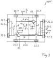
- FIG.3 An alternative embodiment of the pallet transport device 10.1 compared to the pallet transport device 10 according to the Figures 1 and 2 is in Fig.3 Identical components have the same reference number and are not explained again.
- the pallet transport device 10.1 has Fig.3 an x-lifting drive unit 50.1 and a z-lifting drive unit 50.2, which are coupled to the x-lifting device 52 and the z-lifting device 54, respectively, via coupling means to the chassis 20, 30 and the wheel units 22, 32, respectively.
- the x-lift drive unit 50.1 causes the left and right x-carriage 20.1, 20.2 or the left and right wheel units 22.1, 22.2 to be raised or lowered via the x-lifting device 52.
- the z-lift drive unit 52 causes the left and right z-carriages 30 or the left and right z-wheel units 32 to be raised or lowered via the z-lifting device 54.
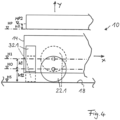
- Fig.4 the height position of an x-wheel unit 22.1 or a z-wheel unit 32.1 in the corner area of the pallet transport device 10 is shown schematically.
- the axis of rotation of the x-wheel unit 22.1 is located relative to the height level HS of the travel path 18 at the height level H0 so that the x-wheel unit 32.1 is in contact with the travel path 18 and, when acted upon by a travel drive unit, enables the pallet transport device 10 to move in the x direction.
- the z-wheel unit 32 is located at the height level H1 and is arranged at a distance from the travel path 18.
- the height level of the pallet receiving unit 16 is in Fig.4 HP.
- the difference (stroke) between the height level H1 and H0 is in Fig.4 designated with h1.
- the difference between the height levels H0 and HS is designated with h12 and depends on the respective diameter of the wheel units 22, 32.
- the z-wheel unit 32.1 or 32.2 is first lowered from the height level H1 by the amount h1 to the height level H0 via the z-lifting device 54 under control of the lifting drive unit 50, so that both the x-wheel units 22 and the z-wheel units 32 are in contact with the travel path 18.
- the lifting drive unit 50 then initiates the x-lifting device 52 the lifting of the x-wheel units 22.1 to the height level H1, so that the x-wheel units 22 come out of contact with the track 18.
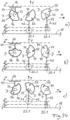
- FIG. 7 A highly schematic structural design of the x-lifting device 52, z-lifting device 54 and y-lifting device 56 is shown, which in the exemplary embodiment are each designed as a cam 74, 75, 76, the cams 74, 75, 76 being on a common rotary shaft 77 are arranged offset in the longitudinal direction, each via an x / z / y coupling element 42, 43, 44 with the corresponding chassis 20, 30 or wheel units 22, 32 or the pallet receiving unit 16 are in communication connection.
- the common axis of rotation 77 is driven, for example, by the common lifting drive unit 50, whereby the lifting movement of the chassis 20, 30 or the wheel units 22, 32 or the pallet receiving unit 16 is controlled in time sequence.
- Fig. 7a, b and c show the states when the pallet receiving unit 16 is lowered.
- Figures 7d, e and f show the states when the pallet receiving unit 16 is raised.
- the lifting device is shown in a highly schematic manner with an x-lifting device 52 for an x-wheel unit 22, a z-lifting device 54 for a z-wheel unit 32.1 and a y-lifting device 56 for the pallet receiving unit 16.
- the lifting devices 52, 54, 56 are formed by an x-cam disk 74, a z-cam disk 75 and a y-cam disk 76, which are arranged rotatably on a common axis of rotation 77 in the direction of rotation D and are coupled to the wheel units 22.1 and 32.1 or pallet receiving unit 16 via schematically shown x-/z-/y-coupling elements 42, 43, 44.
- the coupling elements 42, 43, 44 which can be moved vertically (in the y-direction), are each supported on the circumferential contour of the associated cam disk 74, 75, 76, so that with a corresponding rotation D of the cam disks, the x-wheel unit 22.1, the z-wheel unit 32.1 and the pallet receiving unit 16 carry out a lifting movement in chronological sequence.
- Fig.7 and 34 The curve geometry of the y-curve disk 76 is shown with a solid line, the z-curve disk 75 with a dotted line and the x-curve disk 74 with a dashed line.
- the height level of the guideway 18 is indicated with HS.
- the x-wheel unit 22.1 is initially in contact with the travel path 18.
- the axis of rotation of the x-wheel unit 22.1 is at the height level H0.
- the pallet transport device can be moved in the x-direction.
- the z-wheel unit 32.1 is at the height level H1 and in this state is not in contact with the travel path 18.
- the pallet receiving unit is at the height level HP.
- the rotary shaft 77 is set in rotation D in an anti-clockwise direction via the lifting drive unit 50, whereby the z-wheel unit 32.1 is first lowered down to the travel path 18 (height level HS).
- This state is in Fig. 7b or 34b. Due to the curve geometry of the x/z cam disk 52, 54, further rotations D of the rotation axis 77 raise the x-wheel unit 22.1 in the y-direction to the height level H0, so that as a result the z-wheel unit 32.1 is then in contact with the travel path 18 and the pallet transport device 10 can be moved in the z-direction.
- the pallet receiving unit 16 is in the retracted lower height position HP without any height shift occurring.
- the lifting devices 52, 54, 56 described are as shown in Fig. 1 in each corner area of the chassis 14 of the pallet transport device 10 and coupled to the adjacent x-wheel unit 22 or z-wheel unit 32 in terms of movement via the x / z cam disk 74, 75 in the height direction.
- the pallet receiving unit 16 is coupled in height at the four corner points via its own z-cam 75.
- FIG. 8a and b An alternative embodiment of the lifting devices 52, 54, 56 is shown in a highly schematic form, which are designed as displaceable link units 34, 35, which are coupled to a lifting drive unit 50, which the displacement V of the link units 34, 35 to cause the lifting movement of the chassis 20, 30 or the wheel units 22, 32 accordingly.
- the link unit 34 is designed as a link disk, the lower contour of which controls the lifting movement of the x-wheel units 22 and the upper contour controls the lifting movement of the pallet receiving unit 16.
- the link unit 34 thus represents x/y lifting devices 52, 56.
- the lifting devices 52, 54, 56 are formed by the x-link disk 34 and z-link disk 35, which are mounted in a longitudinally displaceable manner in a V-shape, each of which has a link contour in the direction of displacement, to which the coupling elements 42, 43 for the x-wheel unit 22 and the z-wheel unit are connected in a contact-like manner.
- the x-link disk 34 has a further profile on the top, which is coupled to the coupling element 44 for the pallet receiving unit 16.
- the x-wheel units 22 and the z-wheel unit 32 and the pallet receiving unit 16 carry out a lifting movement in accordance with the respective link disk contour, the temporal sequence and size of which corresponds to the movement sequence as it relates to the Figures 7 and 34
- the respective longitudinal displacement V is brought about by the fact that the link disks 34, 35 are coupled to a spindle nut 46 of a spindle 45 and the spindle 45 itself is set in rotary motion D via the lifting drive unit in order to initiate the displacement movement of the link disks 34, 35 in order to initiate the resulting lifting movements of the wheel units 22, 32.
- Fig. 9 shows a very simplified top view of a shelf system 25, which in the said orthogonal system xz with respect to the travel paths 18 the pallet transport device 10 is formed and also includes a pre-zone 80, within which the pallet transport devices 10 shown can also be moved without being tied to the orthogonal travel system xz of the actual shelf system 25, which is described further below.
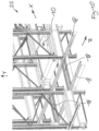
- FIG.10 A perspective detail of a shelving system 25 is shown, which is designed in an orthogonal grid x, y, z, wherein the support system consists of individual profiles arranged in the x, y and z directions, which form travel paths within which the pallet transport device 10 according to the invention is movable in the x and z directions.
- Fig. 11 shows a side view of a structural exemplary embodiment of a pallet transport device 10 with a pallet 12 placed on it.
- the pallet 12 is suitable for an in Fig. 11 to accommodate cargo not shown in detail in individual cases.
- the pallet transport device 10 shown is, in accordance with the previous description, equipped with independent lifting devices in the x, z and y directions, which can be approached separately and controlled via appropriate drive units in order to change the direction of travel x, z or to raise or lower the pallet receiving unit 16 if necessary .
- each x and z wheel unit 22, 32 according to the schematic representation in Fig. 1 each assigned to a lifting device, which is driven by a central lifting drive unit 50.
- each x-wheel unit 22 and each z-wheel unit 32 is assigned a wheel spindle unit 48 for height adjustment, whereby the coupling of the x- and z-wheel units 22, 32 to each other can be carried out via chains or belts 49 or also via a shaft and this type of coupling is also used for the coupling of the lifting drive units 50.1 and 50.2.
- all z-wheel units 32 carry out a corresponding height movement.
- This embodiment variant according to Fig. 20 is characterized by a direct flow of force and enables a lightweight construction, whereby the design principle is the same for both the x and z wheel units 22, 32.
- a spindle unit 48 is inserted into the x/z side, which is coupled to an x-connection profile 38 or a z-connection profile 39, to the end regions of which the x or z wheel unit 22, 32 is connected .
- the wheel spindle units 48 are coupled to one another and to the associated lifting drive unit 50.1, 50.2, for example via a toothed belt 49.
- connection profiles 38, 39 are connected to a rigid frame via frame profiles 37.
- a spindle 45 is directly connected to an x-connection profile 38 and to a z-connection profile 39. to which the associated lifting drive unit 50.1 or 50.2 is directly connected.
- a spindle unit 48 is used in combination with a link 36 to which the wheel units 22, 32 are hinged.
- the opposing spindle units 48 are coupled via a toothed belt 61.
- a rotary lever 33 which is connected to the spindle unit 48 in the respective end region is used, which is coupled to the wheel units 22 or 32, is articulated on the chassis 14, and the rotation of which causes a height shift of the wheel units 22, 32.
- Fig. 25 shows a design example in which a double spindle unit 28 is used, which is coupled to the wheel units 22, 32 via a scissor mechanism 29, which causes a height shift H1 of the wheel units 22 and 32 when the double spindle unit 28 rotates D.
- the scissor mechanisms 29 on opposite sides are coupled to one another via a connecting profile 24.
- the double spindle unit 28 acts on this connecting profile 24 in a displacement manner.
- Fig. 26 The structural exemplary embodiment shown differs from that in Fig. 35 illustrated embodiment in that instead of the simple scissor mechanism 29, a double scissor mechanism 23 is present, which increases stability.
- the embodiment according to Fig. 27 also has a scissor mechanism 29, which is, however, arranged centrally on each side, with an x-connection profile 38 or a z-connection profile 39 being present on each side, which is articulated to the scissor mechanism 29 and connects the associated wheel units 22, 32 per side to one another.
- the structural design variant according to Fig. 28 also has an x and a z connection profile 38, 39, on which the spindle unit 48 acts, the connection profiles 38 each being movable via two parallel, articulated double levers 68 in order to implement the vertical movement of the wheel units 22, 32 when the spindle unit 48 is activated .
- the structural design variant according to Fig. 29 shows a toggle lever mechanism 69 for each wheel side unit, which is articulated to a connecting profile 38 or 39 connecting the wheel units 22 and 32, respectively.
- a spindle unit 48 acts on the toggle lever mechanism 69 in the middle of each side, which causes a displacement movement of the toggle lever mechanism 69 on both sides and thus a vertical movement H1 of the wheel units 22 and 32.
- the toggle lever mechanisms 69 on opposite sides can be coupled to one another via a rigid connection or a chain or a belt 49.
- Fig. 30 shows the use of a double spindle unit 28, to which a horizontally arranged toggle lever mechanism 41 is connected for each wheel unit in the associated x or z direction, via which the vertical movement h1 of the wheel units 22, 32 takes place.
- Fig. 31 shows a design variant in which a double spindle unit 28 is used on each side, which is connected to a displaceable wedge unit 27 via a connecting profile 24, wherein on the underside of each wedge unit 27 a coupling member 26 is connected to the x-connecting profile 38 or the z-connecting profile 39 of the wheel units 22 or 32, so that a vertical movement of the wheel units 22, 32 occurs by moving the wedge unit 27.
- Fig. 32 finally shows a solution in which a double spindle unit 28 is used for each wheel unit 22, 32, to which a toggle lever mechanism 69 is linked for each wheel unit.
- the double spindle units 28 are driven by a drive shaft 83 via the lifting drive units 50.1, 50.2
- a pallet transport device 10 in which the aim according to the invention was that an x-chassis 20 with its x-wheel units 22 and a z-chassis 30 with its z-wheel units 32 can be raised or lowered to different height levels without a lifting movement of the pallet receiving unit 16 having to take place.
- the lifting movement takes place by activating an x-lifting device 52 or a z-lifting device 54 with a lifting drive unit 50 or with an x-lifting drive unit 50.1 and a z-lifting drive unit 50.2.
- the y-lifting device 56 for the pallet receiving unit 16 is also operated via a lifting drive unit 50.
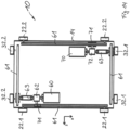
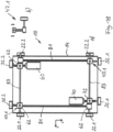
- Fig. 12 shows a schematic plan view of a pallet transport device 10 according to the invention with a lifting drive unit for all chassis or wheel units and two travel drive units 60, 70 for driving the x-/z-wheel units 22, 32 in the required x- or z-direction of the shelving system.
- FIG. 13 to 19 constructive embodiment variants of a pallet transport device 10 according to the invention are shown, in which the x-carriages 20 or x-wheel units 22 and the z-carriages 30 and the z-wheel units 32 can be positioned in different height directions (y-direction) - depending on the desired travel direction x or z -, but according to the invention only two traction drive units, namely a first traction drive unit 60 and a second traction drive unit 70, are used, each of the traction drive units 60, 70 being connected to a right x-chassis 20.1 or right x-wheel units 22.2 and to a left z- Chassis 30.1 or left z-wheel units 32.1 is drive-coupled.
- a first traction drive unit 60 and a second traction drive unit 70 are used, each of the traction drive units 60, 70 being connected to a right x-chassis 20.1 or right x-wheel units 22.2 and to a left z- Chassis 30.1 or left
- the chassis or the wheel units can be arranged in different height positions, there are coupling units between the travel drive units 60, 70, which can implement a height compensation between the respective left x-chassis 20.1 and the right z-chassis 30.2 in terms of drive.
- Fig. 13 shows a design example in which the first travel drive unit 60 and the second travel drive unit 70 are fixed in place. Both the left and right x-wheel units 22.1, 22.2 and the left and right z-wheel units 32.1, 32.2 are coupled to each other via a toothed belt drive 61 on each side. A chain drive can also be used.
- the coupling structure between the fixed travel drive units 60 and 70 is made via a gear 62, to which a universal joint shaft 63 is connected, which creates a drive connection to the left x-wheel units 22.1 and right z-wheel units 32.2 via an interposition of an omega drive 71.
- the universal joint shafts 63 ensure that the x-wheel units 22.1 and the z-wheel units 32.2 are always driven, even when the height position is different, i.e. the wheel units 22.1, 32.2 are always driven, whereby, depending on the direction of travel, the x-wheel units 22.1 or the z-wheel units 32.2 have contact with the travel path 18.
- the same coupling mechanism is used in conjunction with the second travel drive unit 70.
- This design always ensures a constant pre-tension of the toothed belts 61 and enables a simple, fixed attachment of the travel drive units 60, 70 to the pallet chassis 14.
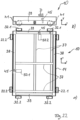
- the design variant shown differs from the design according to Fig. 13 in that the first and second drive units 60, 70 are firmly connected to the left x-chassis 20.1, thus eliminating the need for an intermediate universal joint shaft, and are connected to the right z-chassis 32.1 via the universal joint shaft 63 directly to a z-wheel unit 32.2.
- the connection to the left x-chassis or the left x-toothed belt 61 is again made via an Omega drive 71.
- the right x-wheel units 22.2 and left z-wheel units 32.1 are connected accordingly via the second travel drive unit 70 with the same coupling construction.
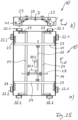
- the execution variation according to Fig. 15 differs from that according to Fig. 14 in that the transmission 62 of the first traction drive unit 60 is connected directly to a left x-wheel unit 22 without the interposition of an omega drive, so that overall no omega drive is required.
- This particularly preferred embodiment is also in Fig. 12 shown in more detail, with the lifting unit 50, the x, y and z lifting devices 52, 54, 56 and the drive mechanism (according to the schematic drawing in Fig. 1 ) are shown in a structurally designed manner.
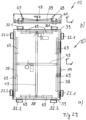
- Fig. 16 shows a further constructive embodiment in which the first traction drive unit 60 acts directly on the left lower x-wheel unit 22.1.
- This lower x-wheel unit 22.1 transmits the rotational movement via the toothed belt 61 to the upper x-wheel unit 22.1.
- a rotary shaft 78 is connected to this upper x-wheel unit 22.1, which is connected via a gear 62 to an omega drive unit 71 for the two right z-wheel units 32.2.
- a pretensioning shaft 41 is present in the toothed belt path of the upper toothed belt 61 to compensate for the tension.
- the drive situation regarding the upper toothed belt 61 is in Fig. 16b shown schematically.
- the first travel drive unit 60 thus moves in the vertical direction with the x-wheel unit 22.1.
- the first travel drive unit 60 is connected directly to the left lower x-wheel unit 22.1 via the gear 62, so that it is coupled in height to the lifting movement of the left x-wheel units 22.
- a further gear 57 is connected directly to the upper left x-wheel unit 22.1, which is coupled to the gear 62 via a shaft unit 81.
- the upper right and left z-wheel units 32 also have an upstream gear 59, which are coupled to one another in terms of drive via a second shaft unit 83.
- the connection between the gear 57 and the further gear 59 is made via a cardan shaft 63.
- the drive coupling of the second travel drive unit 70 to the right x-wheel units 22.2 and left z-wheel units 32.1 is designed accordingly.
- the embodiment according to Fig. 18 shows a shaft drive with sliding joint 47 as a drive coupling device.
- the two right z-wheel units 32.2 are coupled to one another via the second shaft unit 83.
- the first travel drive unit 60 which is connected to a transmission 62 via the second shaft unit 83, is directly connected to the right z-wheel unit 32.2.
- the left x-wheel units 22.1 which are coupled to one another via the first shaft unit 81 and associated transmission units 62, are coupled to one another in the upper left corner area for height compensation via a sliding joint 47.1, wherein the sliding joint 47.1 is shown schematically in Fig. 18b is shown.
- Fig. 19 differs from the embodiment in that the shaft units are replaced by toothed belts 61 and the thrust joint 47.1 is replaced by a horizontal thrust joint 47.2 for height compensation, which is in Fig. 19 b is presented in a highly schematized manner.
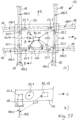
- Fig. 33 is a detail of a shelving system 25 with orthogonal travel paths 18 (x, z direction) and a pallet transport device 10, which has a travel drive unit control device 82, which has a first travel drive unit 60 for driving the right x-wheel units 22.2 and left z-wheel units 32.1 and a second travel drive unit 70 for the left x-wheel units 22.1 and right z-wheel units 32.2.
- the travel path 18 is formed by travel profiles running in the x and z directions.
- a sensor unit 84 is arranged diametrically opposite, which detects a travel path marking 86 attached to the travel path 18 and transmits its signals to the travel drive unit control device 82.
- the travel drive unit control device 82 controls the drive of the first or second travel drive unit 60, 70 in order to ensure exact straight travel at all times.
- the Travel drive unit control device 82 provides a different drive for the right and left x-wheel units 22.1, 22.2 or the right and left z-wheel units 32.1, 32.2 ("tank drive"), so that an exact straight-ahead travel in either the x- or z-direction of the pallet transport device 10 is permanently ensured.
- the two sensor units 84 can also be arranged on one side of the vehicle at the front or rear. Two sensor units arranged in parallel scan the route marking 86 and measure the respective deviations from the target value. An angle measure is formed from the deviation difference, which forms the basis for the corresponding control of the traction drive units 60 or 70 to correct the direction of travel.
- the travel drive unit control device 82 is in communication connection with a higher-level rack system control device 73, which specifies the movement of the pallet transport device 10 to the respective target position in the x or z direction within the rack system 25.
- a further sensor device 67 optionally with several sensor units not shown, is present, which determines the current position data of the pallet transport device 10 with respect to the rack structure, for example the current position or a deviation from the straight line (x or z direction), and supplies the control device 82 with signals accordingly for controlling the first or second travel drive unit 60, 70 for the wheel units 22 or 32.
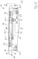
- Fig. 36a is a view from below of a pallet transport device 10 according to Fig. 12 the upper x-side area shown, and Fig. 36b shows a section through this area along section AA of Fig. 36a .
- a mechanical guide roller device is also available shown, which ensures straight-line stability without the use of additional sensor units.
- the guide roller device is present on an x-side and/or on a z-side.
- the guide roller device has a second guide roller unit 96, which consists of two guide rollers spaced apart in the x-direction and which are rotatably connected to the x-chassis 20.1, i.e. they also follow the vertical movement of the x-chassis 20.1 when the direction changes.
- First guide roller units 94 are arranged on the left and right at a distance from the second guide roller unit 96 in the x-direction, each of which consists of a pair of guide rollers, with the guide rollers spaced apart in the x-direction.
- the two second guide roller units 96 are also coupled to the x-chassis 20.1 and thus also carry out a lifting movement when the direction of travel changes.
- the first guide roller unit 94 and the second guide roller unit 96 are each arranged offset in the z-direction.
- a guideway profile 100 forming the guideway 18 is shown, which has an upwardly pointing first flange 90 on the outside and an upwardly pointing second flange 92 on the inside.
- the first guide roller units 94 are arranged so that the inside of the first flange 90 forms a lateral stop for the guide roller units 94.
- the second guide roller unit 96 is arranged offset inwards in the z direction, such that the inside of the second flange 92 forms a lateral stop for the guide roller unit 96, so that the entire guide roller device is precisely guided within the two flanges 90, 92 in the x direction becomes. Because the first guide roller units 94 and the second guide roller unit 96 are connected to the x-carriage 20.1, they come out of engagement with the route profile 100 as soon as the x-carriage 20.1 changes direction is raised. A corresponding guide roller device can also be present on one side in the z direction.
- All guide rollers of the guide roller units 94, 96 are rotatably mounted about a vertical axis of rotation 98 running in the y direction.
- FIG. 37a and b A further embodiment of a pallet transport device according to the invention is shown, which ensures optimal, permanently reliable functioning sensor control for straight-ahead running and changing direction.
- the pallet transport device 10 has two x sensor units 110, which are spaced apart on an x side in the x direction. Furthermore, z sensor units 120 which are spaced apart in the z direction are present on a z side. Both sensor units 110, 120 are connected to the pallet transport device 10 below the vehicle and communicate with a control device 82, 19, which controls the lifting unit 50 and the first and second travel drive units 60, 70.
- Both the routes 18 in the x-direction and in the z-direction are formed by route profiles 100.1 and 100.2, respectively, which have a profile area 102 projecting downwards in the y-direction.
- Both the x sensor units 110 and the z sensor units 120 scan the inside of the profile area 102 of the respective route profile 100.1 or 100.2 and send their determined values to the control device 82, 19.
- the control device 82, 19 calculates an angular position that may deviate from straight running from the signals of the respective x sensor units 110 or z sensor units 120 and controls the first and second drive units 60, 70 based on this calculation Correction of the angular deviation to ensure exact straight running.
- the x-sensor units 110 and the z-sensor units 120 are also used to determine the exact position of the pallet transport device 10 when the direction of travel changes. If a change in direction of travel from the x to the z direction is to be carried out, the control device 82, 19 evaluates the signals from the z-sensor units 120 to determine whether the actual distance to the lower profile area 102 of the z-travel profile 100.2 corresponds to the specified target value for the exact positioning. As soon as a match is determined, the control device 82, 19 causes the lifting drive unit 50 to be activated, whereby a change in direction of travel is carried out by lowering the z-wheel units 32 and then raising the x-wheel units 22.
- the sensor units 110, 120 are preferably designed as laser sensor units. However, sensor units with other operating principles that ensure reliable distance measurement can be used.
Landscapes
- Engineering & Computer Science (AREA)
- Mechanical Engineering (AREA)
- Warehouses Or Storage Devices (AREA)
- Rollers For Roller Conveyors For Transfer (AREA)
- Intermediate Stations On Conveyors (AREA)
Applications Claiming Priority (3)
| Application Number | Priority Date | Filing Date | Title |
|---|---|---|---|
| DE102015001410.2A DE102015001410A1 (de) | 2015-02-06 | 2015-02-06 | Palettentransportvorrichtung |
| EP16000295.2A EP3053855B1 (fr) | 2015-02-06 | 2016-02-05 | Dispositif de transport de palettes |
| EP18203270.6A EP3456663B1 (fr) | 2015-02-06 | 2016-02-05 | Dispositif de transport de palettes |
Related Parent Applications (2)
| Application Number | Title | Priority Date | Filing Date |
|---|---|---|---|
| EP18203270.6A Division EP3456663B1 (fr) | 2015-02-06 | 2016-02-05 | Dispositif de transport de palettes |
| EP16000295.2A Division EP3053855B1 (fr) | 2015-02-06 | 2016-02-05 | Dispositif de transport de palettes |
Publications (2)
| Publication Number | Publication Date |
|---|---|
| EP4345032A2 true EP4345032A2 (fr) | 2024-04-03 |
| EP4345032A3 EP4345032A3 (fr) | 2024-07-03 |
Family
ID=55315291
Family Applications (5)
| Application Number | Title | Priority Date | Filing Date |
|---|---|---|---|
| EP23212590.6A Pending EP4342821A3 (fr) | 2015-02-06 | 2016-02-05 | Dispositif de transport de palettes |
| EP23212583.1A Pending EP4342820A3 (fr) | 2015-02-06 | 2016-02-05 | Dispositif de transport de palettes |
| EP23212592.2A Pending EP4345032A3 (fr) | 2015-02-06 | 2016-02-05 | Dispositif de transport de palettes |
| EP18203270.6A Active EP3456663B1 (fr) | 2015-02-06 | 2016-02-05 | Dispositif de transport de palettes |
| EP16000295.2A Active EP3053855B1 (fr) | 2015-02-06 | 2016-02-05 | Dispositif de transport de palettes |
Family Applications Before (2)
| Application Number | Title | Priority Date | Filing Date |
|---|---|---|---|
| EP23212590.6A Pending EP4342821A3 (fr) | 2015-02-06 | 2016-02-05 | Dispositif de transport de palettes |
| EP23212583.1A Pending EP4342820A3 (fr) | 2015-02-06 | 2016-02-05 | Dispositif de transport de palettes |
Family Applications After (2)
| Application Number | Title | Priority Date | Filing Date |
|---|---|---|---|
| EP18203270.6A Active EP3456663B1 (fr) | 2015-02-06 | 2016-02-05 | Dispositif de transport de palettes |
| EP16000295.2A Active EP3053855B1 (fr) | 2015-02-06 | 2016-02-05 | Dispositif de transport de palettes |
Country Status (3)
| Country | Link |
|---|---|
| US (1) | US10351344B2 (fr) |
| EP (5) | EP4342821A3 (fr) |
| DE (1) | DE102015001410A1 (fr) |
Families Citing this family (49)
| Publication number | Priority date | Publication date | Assignee | Title |
|---|---|---|---|---|
| WO2015134529A1 (fr) * | 2014-03-05 | 2015-09-11 | Pas, Llc | Chariot de stockage à levage automatique |
| JP6845980B2 (ja) * | 2014-12-17 | 2021-03-24 | 伊東電機株式会社 | 物品保管装置及び物品移動装置 |
| ES2888932T3 (es) * | 2015-05-04 | 2022-01-10 | Dematic Nv | Sistema de almacenamiento en almacén automatizado con lanzadera portadora de carga multidireccional |
| CN107614314B (zh) * | 2015-05-29 | 2020-08-04 | 株式会社安川电机 | 输送系统以及输送设备构建方法 |
| GB201604100D0 (en) | 2016-03-10 | 2016-04-20 | Ocado Innovation Ltd | Apparatus for retrieving units from a storage system |
| CA3021233C (fr) | 2016-04-22 | 2023-12-12 | Sew-Eurodrive Gmbh & Co. Kg | Systeme de transport pour transporter un contenant et procede permettant de faire fonctionner une installation de production comprenant un systeme de transport |
| NO341707B1 (en) * | 2016-11-02 | 2018-01-02 | Autostore Tech As | Track sensors for detecting position of vehicle relative to tracks |
| AT15592U1 (de) * | 2016-12-16 | 2018-03-15 | Wu Xi Galaxy Tech Company Limited | Selbstfahrendes shuttle-fahrzeug |
| US11167682B2 (en) * | 2017-01-11 | 2021-11-09 | Biosphere Aerospace, Llc | Modular container transport systems |
| US10947036B2 (en) | 2017-01-11 | 2021-03-16 | Biosphere Aerospace, Llc | Modular container transport systems |
| US10967973B2 (en) | 2017-01-11 | 2021-04-06 | Biosphere Aerospace, Llc | Modular container transport systems |
| US20200398916A1 (en) * | 2017-03-20 | 2020-12-24 | Identytec Gmbh & Co. Kg | Production system with an agv for automatically discharging containers to picking shelves |
| CN108975221B (zh) * | 2017-05-31 | 2024-08-16 | 云南卓沛科技有限公司 | 一种轨道小车 |
| DE102017112669A1 (de) * | 2017-06-08 | 2018-12-13 | Claus Henkel | Modulares Lager-Regalsystem |
| DE102018003872A1 (de) | 2017-06-14 | 2018-12-20 | Sew-Eurodrive Gmbh & Co Kg | Lageranordnung, aufweisend zumindest ein Modul mit Schienen und ein auf den Schienen geführtes Fahrzeug |
| WO2019137866A1 (fr) * | 2018-01-09 | 2019-07-18 | Autostore Technology AS | Mécanisme de déplacement pour véhicule télécommandé |
| CN111727159B (zh) * | 2018-01-09 | 2022-04-22 | 自动存储科技股份有限公司 | 用于遥控式运载工具的移位机构 |
| DE102018201929B4 (de) * | 2018-02-07 | 2025-07-31 | Gebhardt Fördertechnik GmbH | Transportfahrzeug zur automatisierten Bedienung eines Warenlagers |
| GB201803771D0 (en) * | 2018-03-09 | 2018-04-25 | Ocado Innovation Ltd | Transporting device position determining apparatus and method |
| CH714742A1 (de) | 2018-03-12 | 2019-09-13 | Wrh Walter Reist Holding Ag | Fördermodul zum waagrechten Fördern von Gütereinheiten in zwei zueinander senkrecht stehenden Richtungen, sowie Anlage. |
| US10589929B2 (en) * | 2018-03-26 | 2020-03-17 | Frazier Industrial Company | Securely transportable pallet transportation cart |
| CN108326532B (zh) * | 2018-04-17 | 2023-06-27 | 上海先惠自动化技术股份有限公司 | 一种agv装配车托盘用定位结构 |
| NO345059B1 (en) * | 2018-06-12 | 2020-09-14 | Autostore Tech As | Safety device for a delivery vehicle |
| EP3807185B1 (fr) | 2018-06-12 | 2025-03-05 | Autostore Technology As | Dispositif de sécurité pour un véhicule télécommandé, système et procédé d'amélioration de la sécurité opérationnelle d'un système de grille |
| WO2020011355A1 (fr) | 2018-07-11 | 2020-01-16 | O.W. Machinebouw B.V. | Système de stockage, conteneur de stockage et chaîne de poussée |
| JP7026247B2 (ja) * | 2018-09-30 | 2022-02-25 | 上海速▲鋭▼信息技▲術▼有限公司 | 4方向シャトル型運搬ロボット |
| BE1026900B1 (nl) * | 2018-12-20 | 2020-07-22 | Stow Int Nv | Shuttle |
| BE1026996B1 (nl) * | 2019-01-25 | 2020-08-27 | Stow Int Nv | Rekkenstructuur |
| CN111517050B (zh) * | 2019-02-03 | 2023-05-02 | 北京京东乾石科技有限公司 | 运输车及其传动装置 |
| GB201903982D0 (en) * | 2019-03-22 | 2019-05-08 | Ocado Innovation Ltd | Load-handling device |
| WO2020247986A1 (fr) | 2019-06-05 | 2020-12-10 | Storage Management System (Pty) Ltd | Navette bidirectionnelle |
| US11338996B2 (en) * | 2019-08-07 | 2022-05-24 | Hangzhou Huicang Information Technology Company Limited | Rack apparatus, two-wheel drive carriage and automated storage and distribution system |
| DE102019214608A1 (de) * | 2019-09-24 | 2021-03-25 | Gebhardt Fördertechnik GmbH | Transportfahrzeug sowie ein Lager- und Entnahmesystem für Behälter |
| NO346390B1 (en) | 2019-12-20 | 2022-07-04 | Autostore Tech As | Track sensor arrangement for a remotely operated vehicle and a method thereof |
| AT16911U1 (de) * | 2019-12-20 | 2020-11-15 | Knapp Ag | Fahrzeug zum Ein- und Auslagern von Produkten |
| CN111071679A (zh) * | 2019-12-28 | 2020-04-28 | 江苏集萃智能制造技术研究所有限公司 | 一种四向穿梭车 |
| CN111365414A (zh) * | 2020-04-22 | 2020-07-03 | 普罗格智芯科技(湖北)有限公司 | 一种双轴垂直输出减速机及双向驱动系统 |
| EP4168326A1 (fr) | 2020-06-19 | 2023-04-26 | Sew-Eurodrive GmbH & Co. KG | Agencement de rayon de système de stockage et système de stockage |
| EP3960658B1 (fr) * | 2020-08-26 | 2025-06-11 | Jungheinrich Aktiengesellschaft | Véhicule de chargement pour un agencement de stockage empilé |
| GB202014789D0 (en) * | 2020-09-18 | 2020-11-04 | Ocado Innovation Ltd | A load handling device |
| CN115202331A (zh) * | 2021-04-09 | 2022-10-18 | 灵动科技(北京)有限公司 | 自主移动设备、自主移动设备的控制方法及货运系统 |
| DE102021209280A1 (de) * | 2021-08-24 | 2023-03-02 | Stow Robotics Gmbh | Selbstfahrender Wagen für ein Lagersystem mit Haltevorrichtung für Behälter |
| GB202112308D0 (en) * | 2021-08-27 | 2021-10-13 | Ocado Innovation Ltd | A cam mechanism for direction-change assembly of a load-handling device, and related methods and uses |
| US11845609B2 (en) | 2021-10-12 | 2023-12-19 | Frazier Industrial Company | Pallet spacing system and method |
| CN114261670B (zh) * | 2021-11-30 | 2024-05-17 | 华晓精密工业(苏州)有限公司 | 链式举升输送一体设备 |
| ES1291744Y (es) * | 2022-05-24 | 2022-09-05 | Mecalux | Vehículo guiado para el transporte de paletas |
| US12258211B2 (en) * | 2022-08-05 | 2025-03-25 | Frazier Industrial Company | Pallet cart safety structure and method |
| DE102022130831A1 (de) * | 2022-11-22 | 2024-05-23 | Cellgo GmbH | Lagerroboter sowie Verfahren zum Betrieb eines Lagerroboters |
| CN119079352B (zh) * | 2024-08-30 | 2025-09-30 | 上海甲佳智能科技有限公司 | 四向穿梭车的实时位置计算方法 |
Citations (10)
| Publication number | Priority date | Publication date | Assignee | Title |
|---|---|---|---|---|
| DE1556071A1 (de) | 1967-07-25 | 1969-09-11 | Mannesmann Ag | Mechanisiertes Palettenregallager |
| US3978995A (en) | 1973-02-15 | 1976-09-07 | Rapistan, Incorporated | Mobile tier picking apparatus for a warehousing system |
| DE3207860A1 (de) | 1981-03-13 | 1982-09-30 | C.M.F. Costruzioni Metalliche Finsider S.p.A., 57100 Livorno | Foerdereinrichtung fuer eine lagerhausanlage |
| JPH08157016A (ja) | 1994-12-02 | 1996-06-18 | Mitsubishi Heavy Ind Ltd | 縦横走行搬送台車を用いた格納設備 |
| WO2005077789A1 (fr) | 2004-01-16 | 2005-08-25 | Icam S.R.L. | Dispositif de stockage automatise, et vehicule autonome de transfert d'unites de charge dans ledit dispositif de stockage automatise |
| EP2308778A2 (fr) | 2009-10-09 | 2011-04-13 | ICAM S.r.l. | Navette automatique d'entrepôt |
| DE102010005591A1 (de) | 2010-01-22 | 2011-07-28 | Koruna-Lc S.R.O. | Hochregallager zur Lagerung von Paletten, Regalbediengerät, Tandemshuttle, Übergaberegal sowie Verfahren zur Lagerung von Paletten in dem Hochregallager |
| EP2308777B1 (fr) | 2009-10-09 | 2012-12-26 | ICAM S.r.l. | Ensemble de roues de navette d'entrepôt automatique et navette avec cet ensemble de roues |
| US20140031972A1 (en) * | 2012-04-09 | 2014-01-30 | Opex Corporation | Method and apparatus for sorting or retreiving items |
| KR101482519B1 (ko) * | 2013-07-16 | 2015-01-22 | 주식회사 티에스피지 | Mdps 제어 시스템 구성 및 운용 방법 |
Family Cites Families (18)
| Publication number | Priority date | Publication date | Assignee | Title |
|---|---|---|---|---|
| GB1326304A (en) * | 1970-09-08 | 1973-08-08 | Air Preheater | Material handling apparatus |
| JPS59202515A (ja) * | 1983-04-30 | 1984-11-16 | Ishikawajima Harima Heavy Ind Co Ltd | 無人台車の誘導方法 |
| FR2685306B1 (fr) | 1991-12-24 | 1996-06-21 | Etude Mecanisation Automatisat | Magasin de stockage automatise et nouveau type de chariot permettant la mise en place ou l'extraction des produits a l'interieur des zones de stockage. |
| FR2730715B1 (fr) * | 1995-02-22 | 1997-04-04 | Gec Alsthom Syst Et Serv | Chariot automoteur et magasin de stockage desservi par de tels chariots |
| FR2798915B1 (fr) * | 1999-09-27 | 2001-12-21 | Savoye Automated Storage | Magasin de stockage compact automatise |
| WO2007007354A1 (fr) * | 2005-07-07 | 2007-01-18 | Marco Martelli | Système de gestion général d’entreposage de palettes, véhicules automobiles, etc. |
| JP2008080948A (ja) * | 2006-09-27 | 2008-04-10 | Hitachi Plant Technologies Ltd | 走行台車の脱輪防止装置 |
| TWI619660B (zh) * | 2010-12-15 | 2018-04-01 | 辛波提克有限責任公司 | 具有自動運輸機器位置感測的儲存與取出系統及其操作方法 |
| US8965619B2 (en) * | 2010-12-15 | 2015-02-24 | Symbotic, LLC | Bot having high speed stability |
| NO335839B1 (no) * | 2012-12-10 | 2015-03-02 | Jakob Hatteland Logistics As | Robot for transport av lagringsbeholdere |
| CN103895995B (zh) | 2012-12-28 | 2016-04-20 | 昆山光腾智能机械有限公司 | 自动换轨式穿梭车 |
| CN103896000B (zh) * | 2012-12-28 | 2016-04-20 | 昆山光腾智能机械有限公司 | 自动换轨式穿梭车 |
| CN103101737B (zh) * | 2013-02-18 | 2015-06-17 | 齐鲁工业大学 | 一种沿交叉轨道行走的穿梭车 |
| ITTO20130452A1 (it) * | 2013-06-03 | 2014-12-04 | Icam S R L | Navetta di un magazzino automatizzato |
| NL2011021C2 (nl) * | 2013-06-21 | 2014-12-24 | Vanderlande Ind Bv | Systeem voor het opslaan van producthouders en werkwijze voor toepassing van een dergelijk systeem. |
| GB201314313D0 (en) * | 2013-08-09 | 2013-09-25 | Ocado Ltd | Apparatus for retrieving units from a storage system |
| CN203781232U (zh) * | 2014-02-28 | 2014-08-20 | 上海速锐物流科技有限公司 | 一种三维立体行驶的智能穿梭车 |
| US9452883B1 (en) * | 2014-09-26 | 2016-09-27 | Amazon Technologies, Inc. | Re-arrange stored inventory holders |
-
2015
- 2015-02-06 DE DE102015001410.2A patent/DE102015001410A1/de not_active Withdrawn
-
2016
- 2016-02-05 EP EP23212590.6A patent/EP4342821A3/fr active Pending
- 2016-02-05 EP EP23212583.1A patent/EP4342820A3/fr active Pending
- 2016-02-05 EP EP23212592.2A patent/EP4345032A3/fr active Pending
- 2016-02-05 EP EP18203270.6A patent/EP3456663B1/fr active Active
- 2016-02-05 EP EP16000295.2A patent/EP3053855B1/fr active Active
- 2016-02-05 US US15/016,895 patent/US10351344B2/en active Active
Patent Citations (10)
| Publication number | Priority date | Publication date | Assignee | Title |
|---|---|---|---|---|
| DE1556071A1 (de) | 1967-07-25 | 1969-09-11 | Mannesmann Ag | Mechanisiertes Palettenregallager |
| US3978995A (en) | 1973-02-15 | 1976-09-07 | Rapistan, Incorporated | Mobile tier picking apparatus for a warehousing system |
| DE3207860A1 (de) | 1981-03-13 | 1982-09-30 | C.M.F. Costruzioni Metalliche Finsider S.p.A., 57100 Livorno | Foerdereinrichtung fuer eine lagerhausanlage |
| JPH08157016A (ja) | 1994-12-02 | 1996-06-18 | Mitsubishi Heavy Ind Ltd | 縦横走行搬送台車を用いた格納設備 |
| WO2005077789A1 (fr) | 2004-01-16 | 2005-08-25 | Icam S.R.L. | Dispositif de stockage automatise, et vehicule autonome de transfert d'unites de charge dans ledit dispositif de stockage automatise |
| EP2308778A2 (fr) | 2009-10-09 | 2011-04-13 | ICAM S.r.l. | Navette automatique d'entrepôt |
| EP2308777B1 (fr) | 2009-10-09 | 2012-12-26 | ICAM S.r.l. | Ensemble de roues de navette d'entrepôt automatique et navette avec cet ensemble de roues |
| DE102010005591A1 (de) | 2010-01-22 | 2011-07-28 | Koruna-Lc S.R.O. | Hochregallager zur Lagerung von Paletten, Regalbediengerät, Tandemshuttle, Übergaberegal sowie Verfahren zur Lagerung von Paletten in dem Hochregallager |
| US20140031972A1 (en) * | 2012-04-09 | 2014-01-30 | Opex Corporation | Method and apparatus for sorting or retreiving items |
| KR101482519B1 (ko) * | 2013-07-16 | 2015-01-22 | 주식회사 티에스피지 | Mdps 제어 시스템 구성 및 운용 방법 |
Also Published As
| Publication number | Publication date |
|---|---|
| EP3053855A3 (fr) | 2016-11-30 |
| EP3456663A2 (fr) | 2019-03-20 |
| DE102015001410A1 (de) | 2016-08-11 |
| EP4342820A3 (fr) | 2024-06-19 |
| EP3456663A3 (fr) | 2019-06-12 |
| EP4345032A3 (fr) | 2024-07-03 |
| EP3053855B1 (fr) | 2018-11-28 |
| EP4342820A2 (fr) | 2024-03-27 |
| EP3053855A2 (fr) | 2016-08-10 |
| EP4342821A3 (fr) | 2024-06-26 |
| US20160229630A1 (en) | 2016-08-11 |
| US10351344B2 (en) | 2019-07-16 |
| EP4342821A2 (fr) | 2024-03-27 |
| EP3456663B1 (fr) | 2023-11-29 |
Similar Documents
| Publication | Publication Date | Title |
|---|---|---|
| EP3456663B1 (fr) | Dispositif de transport de palettes | |
| EP1638866B1 (fr) | Procede et dispositif pour manipuler des auxiliaires de chargement | |
| EP2794430B1 (fr) | Système d'emmagasinage à rayonnages et son procédé de fonctionnement | |
| DE102013017062A1 (de) | Fördereinheit und Fördersystem zum Fördern von Ladungsträgern | |
| EP2100831B1 (fr) | Véhicule de transport pour palettes et système de transport | |
| AT513930B1 (de) | Regallagersystem mit Förderfahrzeug-Hebevorrichtung | |
| EP3243769B1 (fr) | Procédé et dispositif de stockage de marchandises au détail à l'aide de rangées d'étagères pouvant être reliées | |
| EP2673220B1 (fr) | Appareil de commande de rayonnages à un niveau pour entrer et sortir des marchandises dans et hors d'un entrepôt à rayonnages | |
| EP2885199A1 (fr) | Remorque de train de remorques | |
| DE102013014102A1 (de) | Verfahren und Anlagen zum Fördern von Ladungsträgern | |
| EP1165360B1 (fr) | Systeme de transport pour montage de construction brute de carrosseries de vehicules | |
| EP3292059B1 (fr) | Station de chargement pour charger rapidement des palettes et syteme logistique comprenant la station | |
| EP0090996B1 (fr) | Dispositif pour garer des véhicules automobiles | |
| DE4325446C2 (de) | Regalbediengerät mit Gegengewichtsanordnung und einem einzigen Antriebsmittel für Hub- und Senkbewegung | |
| EP2392523B1 (fr) | Etagère dotée de rouleaux de centrage | |
| WO2013167315A1 (fr) | Dispositif de levage ainsi que dispositif de transbordement de marchandises et procédé de transbordement de marchandises à l'aide d'au moins un tel dispositif de levage | |
| AT500227B1 (de) | Transportwagen zum ein- und auslagern von transportgut | |
| WO2021233507A1 (fr) | Véhicule de transport sans conducteur ayant un appareil de levage de charge utile et un appareil de fixation | |
| DE2920099C2 (de) | Verfahren und Vorrichtung zum Lenken eines Flurförderers | |
| EP1122207B1 (fr) | Fourche à coulissement et à pivotement | |
| DE20210214U1 (de) | Lastaufnahmevorrichtung | |
| DE3406974A1 (de) | Verschieberegal-anlage | |
| DE1949908B1 (de) | Schienengebundene Zugeinheit fuer den Transport langer und/oder schwerer Ladegueter | |
| DE29504727U1 (de) | Fahrerloses Transportsystem |
Legal Events
| Date | Code | Title | Description |
|---|---|---|---|
| PUAI | Public reference made under article 153(3) epc to a published international application that has entered the european phase |
Free format text: ORIGINAL CODE: 0009012 |
|
| STAA | Information on the status of an ep patent application or granted ep patent |
Free format text: STATUS: THE APPLICATION HAS BEEN PUBLISHED |
|
| AC | Divisional application: reference to earlier application |
Ref document number: 3053855 Country of ref document: EP Kind code of ref document: P Ref document number: 3456663 Country of ref document: EP Kind code of ref document: P |
|
| AK | Designated contracting states |
Kind code of ref document: A2 Designated state(s): AL AT BE BG CH CY CZ DE DK EE ES FI FR GB GR HR HU IE IS IT LI LT LU LV MC MK MT NL NO PL PT RO RS SE SI SK SM TR |
|
| PUAL | Search report despatched |
Free format text: ORIGINAL CODE: 0009013 |
|
| RIC1 | Information provided on ipc code assigned before grant |
Ipc: B65G 1/04 20060101AFI20240522BHEP |
|
| AK | Designated contracting states |
Kind code of ref document: A3 Designated state(s): AL AT BE BG CH CY CZ DE DK EE ES FI FR GB GR HR HU IE IS IT LI LT LU LV MC MK MT NL NO PL PT RO RS SE SI SK SM TR |
|
| RIC1 | Information provided on ipc code assigned before grant |
Ipc: B65G 1/04 20060101AFI20240524BHEP |
|
| STAA | Information on the status of an ep patent application or granted ep patent |
Free format text: STATUS: REQUEST FOR EXAMINATION WAS MADE |
|
| 17P | Request for examination filed |
Effective date: 20241218 |
|
| STAA | Information on the status of an ep patent application or granted ep patent |
Free format text: STATUS: EXAMINATION IS IN PROGRESS |
|
| 17Q | First examination report despatched |
Effective date: 20260310 |