EP4345331A1 - Scheibenbremse - Google Patents
Scheibenbremse Download PDFInfo
- Publication number
- EP4345331A1 EP4345331A1 EP22197970.1A EP22197970A EP4345331A1 EP 4345331 A1 EP4345331 A1 EP 4345331A1 EP 22197970 A EP22197970 A EP 22197970A EP 4345331 A1 EP4345331 A1 EP 4345331A1
- Authority
- EP
- European Patent Office
- Prior art keywords
- brake
- disc
- groove
- friction surface
- back plate
- Prior art date
- Legal status (The legal status is an assumption and is not a legal conclusion. Google has not performed a legal analysis and makes no representation as to the accuracy of the status listed.)
- Withdrawn
Links
Images


Classifications
-
- F—MECHANICAL ENGINEERING; LIGHTING; HEATING; WEAPONS; BLASTING
- F16—ENGINEERING ELEMENTS AND UNITS; GENERAL MEASURES FOR PRODUCING AND MAINTAINING EFFECTIVE FUNCTIONING OF MACHINES OR INSTALLATIONS; THERMAL INSULATION IN GENERAL
- F16D—COUPLINGS FOR TRANSMITTING ROTATION; CLUTCHES; BRAKES
- F16D65/00—Parts or details
- F16D65/02—Braking members; Mounting thereof
- F16D65/04—Bands, shoes or pads; Pivots or supporting members therefor
- F16D65/092—Bands, shoes or pads; Pivots or supporting members therefor for axially-engaging brakes, e.g. disc brakes
- F16D65/095—Pivots or supporting members therefor
-
- F—MECHANICAL ENGINEERING; LIGHTING; HEATING; WEAPONS; BLASTING
- F16—ENGINEERING ELEMENTS AND UNITS; GENERAL MEASURES FOR PRODUCING AND MAINTAINING EFFECTIVE FUNCTIONING OF MACHINES OR INSTALLATIONS; THERMAL INSULATION IN GENERAL
- F16D—COUPLINGS FOR TRANSMITTING ROTATION; CLUTCHES; BRAKES
- F16D55/00—Brakes with substantially-radial braking surfaces pressed together in axial direction, e.g. disc brakes
- F16D55/02—Brakes with substantially-radial braking surfaces pressed together in axial direction, e.g. disc brakes with axially-movable discs or pads pressed against axially-located rotating members
- F16D55/22—Brakes with substantially-radial braking surfaces pressed together in axial direction, e.g. disc brakes with axially-movable discs or pads pressed against axially-located rotating members by clamping an axially-located rotating disc between movable braking members, e.g. movable brake discs or brake pads
- F16D55/224—Brakes with substantially-radial braking surfaces pressed together in axial direction, e.g. disc brakes with axially-movable discs or pads pressed against axially-located rotating members by clamping an axially-located rotating disc between movable braking members, e.g. movable brake discs or brake pads with a common actuating member for the braking members
- F16D55/225—Brakes with substantially-radial braking surfaces pressed together in axial direction, e.g. disc brakes with axially-movable discs or pads pressed against axially-located rotating members by clamping an axially-located rotating disc between movable braking members, e.g. movable brake discs or brake pads with a common actuating member for the braking members the braking members being brake pads
- F16D55/226—Brakes with substantially-radial braking surfaces pressed together in axial direction, e.g. disc brakes with axially-movable discs or pads pressed against axially-located rotating members by clamping an axially-located rotating disc between movable braking members, e.g. movable brake discs or brake pads with a common actuating member for the braking members the braking members being brake pads in which the common actuating member is moved axially, e.g. floating caliper disc brakes
-
- F—MECHANICAL ENGINEERING; LIGHTING; HEATING; WEAPONS; BLASTING
- F16—ENGINEERING ELEMENTS AND UNITS; GENERAL MEASURES FOR PRODUCING AND MAINTAINING EFFECTIVE FUNCTIONING OF MACHINES OR INSTALLATIONS; THERMAL INSULATION IN GENERAL
- F16D—COUPLINGS FOR TRANSMITTING ROTATION; CLUTCHES; BRAKES
- F16D69/00—Friction linings; Attachment thereof; Selection of coacting friction substances or surfaces
- F16D2069/004—Profiled friction surfaces, e.g. grooves, dimples
Definitions
- the invention relates to a disc brake, in particular, a disc brake for vehicles.
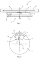
- Fig. 1 shows a principle illustration of a disc brake 1 according to the state-of-the-art.
- the disc brake 1 comprises a brake disc 2 and a brake pad 3 and a caliper (not shown).
- the brake pad 3 comprises a back plate 4 and a lining material 5.
- the back plate 4 is configured to be supported on a caliper (not shown) of the disc brake 1 and the lining material 5 is attached to the back plate 4.
- the lining material 5 comprises a friction surface 6 which applies a friction force F R to the rotating brake disc 2 when the brake pad 3 is pressed on the brake disc 2 by a braking force F.
- a location where the braking force is applied to the brake pad is selected such that it generates a compensating torque which, e.g., is shown in document EP 3245417 B1 ; however, for a proper effect, the location would have to be changed depending on the wear of the brake pad.
- components of the disc brake are formed exceptionally stiff and large in order to withstand the taper wear moment and, consequently, to avoid taper wear.
- this measure increases the weight of the components of the brake and the costs.
- the object underlying the invention is to eliminate the above-mentioned problem and to avoid a negative effect of the taper wear.
- a disc brake comprises a brake disc, two brake pads facing each other, wherein the brake pads respectively comprise a back plate and a lining material attached to the back plate.
- Each brake pad comprises an incoming side which is a leading side of the brake pad when the brake disc rotates in the rotating direction when the vehicle moves in the forward direction and an outgoing side which is a side opposite to the incoming side in the rotating direction of the brake disc.
- the lining material has a thickness towards the brake disc, which thickness increases from the outgoing side to the incoming side.
- the disc brake further comprises a clamping unit comprising the brake pads and a caliper comprising tension struts connecting a portion, where one of the two brake pads is supported, with another portion, where the other one of the two brake pads (3) is supported, and the clamping unit is configured to be supported in a rotary manner with respect to a carrier of the vehicle on the carrier, wherein, on the outgoing side, the back plate of each brake pad is configured to be supported in a rotary manner by the carrier.
- the back plates comprise components of a fixed bearing to support the back plates on the carrier.
- the fixed bearing comprises components of half shell bearing.
- the back plates comprise components of a loose bearing to be configured to be supported on the carrier, and, on the incoming side, the back plates and the caliper respectively comprise components of a fixed bearing to support the back plates in a rotary manner by the caliper.
- a friction surface of the lining material is configured to apply a friction force to the rotating brake disc
- the lining material comprises a groove in the friction surface extending towards the back plate, and, in a plane of the friction surface, having a width and a center line of the width, and the friction surface has a centroid, wherein the center line of the width of the groove is located in places other than the centroid so that it does not pass through the centroid.
- the friction surface is configured to contact the rotating brake disc, and the groove is provided in a direction perpendicular to a tangential direction of the direction of rotation of the brake disc.
- the friction surface is configured to contact the rotating brake disc, and the groove is provided in a direction parallel to a tangential direction of the direction of rotation of the brake disc.
- the groove has a cross section of one of a concave shape, and a rectangular shape, in particular, of a U-shape and a V-shape.
- flanks of the V-shaped groove respectively enclose a different angle with the friction surface.
- the groove extends up to the back plate.
- the cross-section of the groove changes in a direction along the friction surface.
- Fig. 2 shows a principle illustration of first embodiment of a disc brake 1 according to the invention in direction of an axis A of a brake disc 2 and Fig. 3 shows a principle illustration of a brake pad 3 of the embodiment of Fig. 2 in a direction perpendicular to the axis A of the brake disc 2.
- the disc brake 1 of a vehicle comprises the brake disc 2 and the brake pad 3.
- the brake disc 2 rotates in a direction of rotation R.
- the brake pad 3 comprises a back plate 4 and a lining material 5.
- the back plate 4 is configured to be supported on a caliper (not shown in Fig. 2 ) of the disc brake 1 and the lining material 5 is attached to the back plate 4.
- the lining material 5 comprises a friction surface 6 which applies a friction force F R to the rotating brake disc 2 when the brake pad 3 is pressed on the brake disc 2 by a braking force F.
- the lining material 5 comprises a groove 7 in the friction surface 6 extending towards the back plate 4.
- the groove 7 partitions the friction surface 6 into two partial friction surfaces 6', 6" of an entire friction surface 6.
- the groove 7 has a width 7w and a center line 7c of the width 7w along the friction surface 6.
- the entire friction surface 6 is defined as the friction surface 6 of the lining material 5 without considering the groove 7.
- the entire friction surface 6 has a centroid C and the groove 7 is located in a place other than the centroid so that it does not pass through the centroid C.
- the groove 7 is displaced from the centroid such that a surface area of the partial friction surface 6' located at an incoming side S i of the brake disc 2 which is a leading side of the brake pad 3 when the brake disc 2 rotates in the rotating direction R when the vehicle moves in the forward direction is larger than a surface area of the partial friction surface 6" located at an outgoing side S o of the brake disk 2 which is a side opposite to the incoming side S i in the rotating direction R of the brake disc 2.
- the groove 7 is provided in a direction perpendicular to a tangential direction of a direction of rotation R of the brake disc 2, therefore, radially to the brake disc 2.
- the groove 7 has a V-shape, wherein flanks 7', 7" of the V-shaped groove 7 respectively enclose a different angle with the friction surface 6.
- the groove 7 has a U-shape, a V-shape having flanks 7', 7" enclosing identical angles with the friction surface 6, a concave shape, or a rectangular shape.
- the groove 7 extends up to the back plate 4. In alternative embodiments, the groove 7 does not extend up to the back plate 4 but its depth is smaller than a thickness of the lining material 5.
- the cross-section of the groove 7 in a direction along the friction surface 6 is identical. In alternative embodiments, the cross-section of the groove changes in the direction along the friction surface 6.
- the friction surface 6 contacts the rotating brake disc 2 and the groove 7 is provided, along the friction surface 6, in a direction perpendicular to a tangential direction of the direction of rotation R of the brake disc 2.
- the groove 7 is provided, along the friction surface 6, parallel to the tangential direction of the direction of rotation R of the brake disc 2, the groove 7 encloses, along the friction surface 6, another angle with the tangential direction of rotation of the brake disc 2, or the groove 7 is concentric to the brake disc 2.
- the moment M which would cause the taper wear is compensated by a compensation moment M comp caused by different counter forces F 1 and F 2 acting in the respective centroid of the partial friction surfaces 6', 6" of the friction surface 6.
- the pressure generated on the friction surface 6 by a braking force F is uniform, and, therefore, due to different sizes of the parts 6', 6" of the friction surface 6 different counter forces F 1 and F 2 result.
- Fig. 4 shows a principle illustration of a disc brake 1 of a second embodiment
- Fig. 5 shows a principle illustration of a brake pad 3 of a disc brake 1 of the second embodiment.
- the disc brake 1 comprises the brake disc 2, two brake pads 3 facing each other and a caliper 8.
- the brake pads 3 respectively comprise the back plate 4 and the lining material 5.
- Each brake pad 3 comprises the incoming side S i , and the outgoing side S o .
- the caliper 8 and the brake pads 3 are configured such that the brake pads 3 are supported on the caliper 8.
- the caliper 8 comprises tension struts 9 connecting a portion 10 of the caliper 8 where one of the two brake pads 3 is supported with a portion 10 of the caliper 8 where the other one of the two brake pads 3 is supported.
- At least one of the caliper 8 and of the two brake pads 3 is configured to provided its/their deformation during braking such that a point of application of a resulting counterforce F Res from the brake disc 2 to the brake pads 3 is located closer to the incoming side S i then to the outgoing side S o .
- the brake pads 3, respectively including the back plate 4 and the lining material 5, and the caliper 8, including the tension struts 9 and the portions 10, are components of a clamping unit such that the caliper 8 is also a component of the clamping unit.
- the back plate 4 has a non-uniform thickness and the thickness towards the outgoing side is smaller than towards the incoming side. Due to this characteristic, the stiffness of the back plate 4 and, therefore, of the brake pad 3 towards the outgoing side S o is smaller than the stiffness of the back plate 4 and, therefore, of the brake pad 3 towards the incoming side S i . This results in a behavior with a reduced counterforce from the brake disc 2 to the brake pads 3 towards the outgoing side S o which in turn results in a point of application of the resulting counterforce F Res which is located closer to the incoming side S i than to the outgoing side S o .
- the brake disc 2 has the axis A and the lining material 4 comprises an inner edge E i facing the axis A and an outer edge E o averted from the axis A.
- At least one of the caliper 8 and the two brake pads 3 is configured to provide its/their deformation during braking such that a point of application of the resulting counterforce F Res from the brake disc 2 to the brake pads 3 is located closer to the outer edge E o than to the inner edge E i .
- either the caliper 8 or the two brake pads 3 are configured to provide their deformation during braking such that a point of application of a resulting counterforce from the brake disc 2 to the brake pads 3 is located closer to the outer edge E o than to the inner edge E i .
- the groove 7 of the first embodiment can alternatively be provided in the brake pad 3 of the second embodiment.
- Fig. 6 shows a cross-sectional view of a disc brake 1 according to a third embodiment, wherein the caliper 8 is cut in a sectional plane including a surface of the brake disc 2 such that tension struts 9 are cut and there is a plan view onto one of the brake pads 3.
- the caliper 8 comprises the tension struts 9 connecting a portion 10 of the caliper 8 where one of the two brake pads 3 is supported with a portion of the caliper 8 where the other one of the two brake pads 3 is supported.
- the portions 10, where the brake pads 3 are supported, and the tension struts 9 are integrally formed as one component such that the portions where the brake pads 3 are supported and, in particular, the tension struts 9 are made of the same material.
- the caliper 8 is made of several components which are made of different materials.
- the tension struts 9 closer to the incoming side S i of the brake pad 3 has another stiffness than the tension struts 9 closer to the outgoing side S o of the brake pad 3.
- a cross-section of the tension strut 9 closer to the incoming side S i differs from the cross-section of the tension strut 9 closer to the outgoing side S o .
- the stiffness of the tension strut 9 closer to the incoming side Si is larger than the stiffness of the tension strut 9 closer to the outgoing side S o .
- the lining material 5 comprises an inner edge E i facing the axis A and an outer edge E o averted from the axis A.
- the stiffness of the tension struts 9 is distributed such that, of one of the tension struts 9, the stiffness closer to the inner edge is larger than the stiffness closer to the outer edge E o . This is achieved by choosing a shape of the cross-section in an appropriate manner. In order to reduce or eliminate the taper wear in the radial direction, from the inner edge E i to the outer edge E o , the distribution of the stiffness in each of the tension struts 9 is accordingly set.
- the two brake pads 3 and the caliper 8 are not all configured to provide their deformation during braking such that a point of application of a resulting counterforce from the brake disc 2 to the brake pads 3 is located closer to the outer edge E o than to the inner edge E i .
- the groove 7 of the first embodiment can alternatively be provided in the brake pad 3 of the third embodiment.
- Fig. 7 shows a principle illustration of a disc brake 1 according to a fourth embodiment.
- the disc brake 1 comprises the brake disc 2, the two brake pads 3 facing each other, wherein the brake pads 3 respectively comprise the back plate 4 and the lining material 5.
- Each brake pad 3 comprises the incoming side S i and the outgoing side S o .
- the lining material 5 has a thickness towards the brake disc 2, which thickness increases from the outgoing side S o to the incoming side S i .
- the disc brake 1 further comprises the caliper 8, wherein the caliper 8 and the brake pads 3 are configured such that the brake pads 3 are supported on the caliper 8, and the caliper 8 is configured to be supported in a rotary manner with respect to a carrier 11 of the vehicle on the carrier.
- the back plate 4 of each brake pad 3 is configured to be supported in a rotary manner by the carrier 11.
- the back plates 4 comprise components of a fixed bearing to support the back plates 4 in a rotary manner on the carrier 11 by means of the fixed bearings.
- the brake pads 3 rotate about the fixed bearings so that the effect of the taper wear is considered in the wear of the lining materials 5 by the varying thickness of the lining material 5 in order to avoid the problems usually caused by the taper wear.
- a desired wear distribution can be achieved by a position of the application point of the brake force in an optimal predefined distance to the fixed bearings.
- Fig. 8 shows a principle illustration of an alternative of the disc brake 1 of Fig. 7 .
- Fig. 8 merely shows one brake pad 3, nevertheless, this disc brake 1 comprises two brake pads 3 as shown in Fig. 7 .
- This disc brake 1 distinguishes from the disc brake 1 in Fig. 7 in the type of the fixed bearings.
- the fixed bearings comprise components of a half shell bearing.
- the groove 7 of the first embodiment can alternatively be provided in the brake pad 3 of the fourth embodiment.
- Fig. 9 shows a principle illustration of a disc brake 1 according to a fifth embodiment.
- the disc brake 1 according to the fifth embodiment distinguishes from the disc brake 1 of Fig. 7 in that the back plates 4 are not supported on the carrier 11 by fixed bearings but by loose bearings on the outgoing side S o of the brake pads. Therefore, the back plates 4 and the carrier 11 respectively comprise components of the loose bearings to support the back plates 4 on the carrier 11.
- the back plate 4 and the caliper 8 illustrated by a bracket respectively comprise components of a fixed bearing to support the back plate 4 by the caliper 8.
- the groove 7 of the first embodiment can alternatively be provided in the brake pad 3 of the fifth embodiment.
- the effect of the considered taper wear is enabled by the fixed bearings on the incoming side S i about which the brake pads 3 can rotate and the rotatable caliper 8. Further, in order to enable a defined wear of the lining materials 5, the brake pads 3 are supported on the carrier 11 by means of the loose bearings. The position of the application point of the brake force F can be defined in an optimal predefined distance to the fixed bearings.
Landscapes
- Engineering & Computer Science (AREA)
- General Engineering & Computer Science (AREA)
- Mechanical Engineering (AREA)
- Braking Arrangements (AREA)
Priority Applications (3)
| Application Number | Priority Date | Filing Date | Title |
|---|---|---|---|
| EP22197970.1A EP4345331A1 (de) | 2022-09-27 | 2022-09-27 | Scheibenbremse |
| PCT/EP2023/076222 WO2024068465A1 (en) | 2022-09-27 | 2023-09-22 | Disk brake |
| EP23772526.2A EP4594652A1 (de) | 2022-09-27 | 2023-09-22 | Scheibenbremse |
Applications Claiming Priority (1)
| Application Number | Priority Date | Filing Date | Title |
|---|---|---|---|
| EP22197970.1A EP4345331A1 (de) | 2022-09-27 | 2022-09-27 | Scheibenbremse |
Publications (1)
| Publication Number | Publication Date |
|---|---|
| EP4345331A1 true EP4345331A1 (de) | 2024-04-03 |
Family
ID=83506096
Family Applications (2)
| Application Number | Title | Priority Date | Filing Date |
|---|---|---|---|
| EP22197970.1A Withdrawn EP4345331A1 (de) | 2022-09-27 | 2022-09-27 | Scheibenbremse |
| EP23772526.2A Pending EP4594652A1 (de) | 2022-09-27 | 2023-09-22 | Scheibenbremse |
Family Applications After (1)
| Application Number | Title | Priority Date | Filing Date |
|---|---|---|---|
| EP23772526.2A Pending EP4594652A1 (de) | 2022-09-27 | 2023-09-22 | Scheibenbremse |
Country Status (2)
| Country | Link |
|---|---|
| EP (2) | EP4345331A1 (de) |
| WO (1) | WO2024068465A1 (de) |
Citations (6)
| Publication number | Priority date | Publication date | Assignee | Title |
|---|---|---|---|---|
| US3199633A (en) * | 1962-06-15 | 1965-08-10 | Automotive Prod Co Ltd | Closed loop, spot type, disc brakes |
| US4299311A (en) * | 1979-06-29 | 1981-11-10 | Toyota Jidosha Kogyo Kabushiki Kaisha | Disc brake |
| US20070068747A1 (en) * | 2005-09-27 | 2007-03-29 | Akebono Corporation (North America) | Self-energizing sliding caliper |
| US20090145702A1 (en) * | 2007-12-06 | 2009-06-11 | Kelsey-Hayes Company | Brake pad for a vehicle disc brake assembly |
| US20170363160A1 (en) * | 2016-06-21 | 2017-12-21 | Nissan North America, Inc. | Brake pad |
| EP3245417B1 (de) | 2014-12-01 | 2019-02-20 | WABCO Europe BVBA | Pneumatisch oder elektromechanisch betätigte scheibenbremse für nutzfahrzeuge |
-
2022
- 2022-09-27 EP EP22197970.1A patent/EP4345331A1/de not_active Withdrawn
-
2023
- 2023-09-22 EP EP23772526.2A patent/EP4594652A1/de active Pending
- 2023-09-22 WO PCT/EP2023/076222 patent/WO2024068465A1/en not_active Ceased
Patent Citations (6)
| Publication number | Priority date | Publication date | Assignee | Title |
|---|---|---|---|---|
| US3199633A (en) * | 1962-06-15 | 1965-08-10 | Automotive Prod Co Ltd | Closed loop, spot type, disc brakes |
| US4299311A (en) * | 1979-06-29 | 1981-11-10 | Toyota Jidosha Kogyo Kabushiki Kaisha | Disc brake |
| US20070068747A1 (en) * | 2005-09-27 | 2007-03-29 | Akebono Corporation (North America) | Self-energizing sliding caliper |
| US20090145702A1 (en) * | 2007-12-06 | 2009-06-11 | Kelsey-Hayes Company | Brake pad for a vehicle disc brake assembly |
| EP3245417B1 (de) | 2014-12-01 | 2019-02-20 | WABCO Europe BVBA | Pneumatisch oder elektromechanisch betätigte scheibenbremse für nutzfahrzeuge |
| US20170363160A1 (en) * | 2016-06-21 | 2017-12-21 | Nissan North America, Inc. | Brake pad |
Also Published As
| Publication number | Publication date |
|---|---|
| WO2024068465A1 (en) | 2024-04-04 |
| EP4594652A1 (de) | 2025-08-06 |
Similar Documents
| Publication | Publication Date | Title |
|---|---|---|
| JP5512337B2 (ja) | 鉄道車両用ブレーキライニング | |
| US3509973A (en) | Anti-squeal disc braking device | |
| US7370736B2 (en) | Laminated shim for disc brake and pad unit having the laminated shim | |
| CN103562587B (zh) | 铁道车辆用制动衬片及具有该铁道车辆用制动衬片的盘形制动器 | |
| US6705434B1 (en) | Multiple disc brake system | |
| US3972393A (en) | Friction pad and support for a disc brake | |
| AU2016317850B2 (en) | Wear optimized pad design | |
| US6520296B1 (en) | Multiple disc brake system | |
| US11959522B2 (en) | Brake assembly | |
| US20110127124A1 (en) | Coulomb Friction Damped Disc Brake Caliper Bracket | |
| JP2003507682A (ja) | フォイルスラストベアリング | |
| US5386890A (en) | Disk brake having means to prevent uneven brake pad wear | |
| EP4345331A1 (de) | Scheibenbremse | |
| EP4345333A1 (de) | Scheibenbremse | |
| EP4345332A1 (de) | Bremsbelag und scheibenbremse mit dem bremsbelag | |
| US11035426B2 (en) | Caliper braking system for aircraft landing gear having a plurality of brake disk clamping zones | |
| EP0966621A1 (de) | Bremsbelag für scheibenbremse | |
| EP0644348B1 (de) | Flugzeugbremse mit ergänzender Struktur zur Verbesserung der Druckverteilung in den Bremsscheiben | |
| US20230167866A1 (en) | Disk brake system with single-sided pressure application | |
| US4890698A (en) | Disk brake and brake pad utilizable in such a brake | |
| US20070068747A1 (en) | Self-energizing sliding caliper | |
| JP7213994B2 (ja) | ディスクブレーキ | |
| JP3139104B2 (ja) | ディスクブレーキ | |
| US20250327498A1 (en) | Brake pad set and vehicle brake | |
| JPH09196092A (ja) | ディスクブレーキ装置 |
Legal Events
| Date | Code | Title | Description |
|---|---|---|---|
| PUAI | Public reference made under article 153(3) epc to a published international application that has entered the european phase |
Free format text: ORIGINAL CODE: 0009012 |
|
| STAA | Information on the status of an ep patent application or granted ep patent |
Free format text: STATUS: THE APPLICATION HAS BEEN PUBLISHED |
|
| AK | Designated contracting states |
Kind code of ref document: A1 Designated state(s): AL AT BE BG CH CY CZ DE DK EE ES FI FR GB GR HR HU IE IS IT LI LT LU LV MC MK MT NL NO PL PT RO RS SE SI SK SM TR |
|
| STAA | Information on the status of an ep patent application or granted ep patent |
Free format text: STATUS: REQUEST FOR EXAMINATION WAS MADE |
|
| 17P | Request for examination filed |
Effective date: 20241004 |
|
| RBV | Designated contracting states (corrected) |
Designated state(s): AL AT BE BG CH CY CZ DE DK EE ES FI FR GB GR HR HU IE IS IT LI LT LU LV MC MK MT NL NO PL PT RO RS SE SI SK SM TR |
|
| GRAP | Despatch of communication of intention to grant a patent |
Free format text: ORIGINAL CODE: EPIDOSNIGR1 |
|
| STAA | Information on the status of an ep patent application or granted ep patent |
Free format text: STATUS: GRANT OF PATENT IS INTENDED |
|
| INTG | Intention to grant announced |
Effective date: 20250314 |
|
| STAA | Information on the status of an ep patent application or granted ep patent |
Free format text: STATUS: THE APPLICATION IS DEEMED TO BE WITHDRAWN |
|
| 18D | Application deemed to be withdrawn |
Effective date: 20250715 |