EP4345375A1 - Dispositif de tir au sol - Google Patents
Dispositif de tir au sol Download PDFInfo
- Publication number
- EP4345375A1 EP4345375A1 EP22199217.5A EP22199217A EP4345375A1 EP 4345375 A1 EP4345375 A1 EP 4345375A1 EP 22199217 A EP22199217 A EP 22199217A EP 4345375 A1 EP4345375 A1 EP 4345375A1
- Authority
- EP
- European Patent Office
- Prior art keywords
- base
- fire device
- burner
- casing
- standing
- Prior art date
- Legal status (The legal status is an assumption and is not a legal conclusion. Google has not performed a legal analysis and makes no representation as to the accuracy of the status listed.)
- Pending
Links
Images


Classifications
-
- F—MECHANICAL ENGINEERING; LIGHTING; HEATING; WEAPONS; BLASTING
- F23—COMBUSTION APPARATUS; COMBUSTION PROCESSES
- F23D—BURNERS
- F23D3/00—Burners using capillary action
Definitions
- the application relates to a stationary fire device according to the preamble of claim 1.
- Standing fire devices are known as decorative items as well as light and heat sources for indoor and outdoor areas.
- a fuel reservoir usually housed in a base of the standfire device, feeds a flame.
- the flame is surrounded by a transparent cover, which is usually attached to the base, for example is removably supported on the base.
- An odorless burning substance such as ethanol, is usually used as fuel.
- the cover is designed to prevent dangers caused by the flame spreading to objects in the vicinity of the fire pit or by parts of the body of people or pets in the vicinity of the fire pit accidentally entering the area of the flame.
- the cover which is usually made of heat-resistant glass, allows people nearby to see the flame and to illuminate the area around the fire pit with the flame.
- the casing also serves to direct air supply and exhaust air for the operation of the burner.
- the casing is open at a lower and an upper end to allow air to flow through the casing.
- the air supply required to feed the flame passes through the lower end of the casing to a burning zone of the standing fire device.
- Exhaust air generated by the flame rises due to the heat in the casing and exits through the upper end of the casing.
- the resulting air flow also stretches the flame in a vertical direction. This contributes to the luminous effect of the standing fire device and also to the aesthetic effect of the flame.
- a stationary fire device with guide elements is described.
- a The base of the standing fire device comprises a plurality of individual parts that are assembled to form the base.
- a plurality of individually manufactured guide elements are each surrounded by ring elements at the top and bottom.
- the guide elements are also enclosed in the lateral direction, that is in the radial direction in relation to a vertical axis of the stationary fire device, both inwardly and outwardly by a sleeve element.
- a spiral-shaped supply air duct is formed between the inner and outer sleeve elements by each pair of adjacent guide elements.
- the device described can have disadvantages due to the fact that the geometry of the base is relatively complex.
- the base is assembled from a relatively large number of individual parts. This increases manufacturing costs.
- a selection of suitable materials for the production of the base and the individual parts is limited due to the complex geometry of the base.
- the EN 20 2018 004 601 U1 A fire column device in which an outer shell in the form of a glass cylinder is removable and placed from above over the guide elements, which are designed as helical sheets and are attached to the side of a base part of the device.
- the outer shell is supported on pins that protrude laterally from the base part.
- a stationary fire device therefore comprises a base which is designed to accommodate a burner, and a casing which is arranged on the base in a movable, in particular removable, manner and which is designed such that it contains a flame of the burner when the stationary fire device is operated encloses in a lateral direction.
- the stationary fire device is designed in such a way that ambient air, which is required to operate the stationary fire device, enters the base from the side and is directed upwards to a combustion zone of the burner via at least one air duct in the area of the base.
- the at least one air duct is at least partially delimited in the lateral direction inwards by an outside of the burner.
- the base By means of the delimitation of the at least one air channel in the lateral direction inwards, which occurs at least partially through an outside of the burner, production of the base from a few parts is favored. It also allows the base to be manufactured by casting. This particularly facilitates the production of the base as a single casting. This allows the base to be manufactured with relatively little processing effort. It also allows the base to be manufactured using castable materials.
- the lateral direction may correspond to a radial direction with respect to a vertical axis of the stationary fire device.
- the stationary fire device can have an at least essentially cylindrical, in particular twisted cylindrical, and/or column-like structure along the vertical axis.
- the base may include a base wall with an inside.
- the at least one air duct can be at least partially delimited in the lateral direction outwards by the inside of the base wall.
- the base can comprise at least one projection which is arranged on the inside of the base wall.
- the at least one air duct can be at least partially delimited by the projection in the circumferential direction of the base.
- the projection can be designed at least in sections as a spiral-shaped ridge to form one or more spiral-shaped air channels.
- the base can comprise a plurality of projections which are arranged offset from one another in the circumferential direction of the base on the inside of the base wall. Subdividing the inside of the base wall into several air channels can help direct the air.
- the base can have a foot section and at least one support section.
- the base wall can be at least partially attached to the foot section by means of the support section be arranged and/or designed to be supported.
- the base can have at least one air inlet area which is arranged adjacent to the at least one support section. Each air inlet area can be assigned to an air duct of the stationary fire device.
- the base may be configured to receive the burner through an opening at a top of the base.
- the burner can comprise a fuel reservoir.
- the at least one air channel can be at least partially delimited by a side surface of the fuel reservoir.
- the burner can comprise a, in particular sleeve-shaped, burner outer casing, wherein the at least one air channel is at least partially delimited by a side surface of the burner outer casing.
- the base can be made in one piece of material with regard to the features described above. In particular, the entire base can be made in one piece of material. Additionally or alternatively, the base can be designed as a cast part.
- the base may include concrete.
- the concrete can be self-compacted, fiber-reinforced and/or high-strength concrete.
- the base can in particular be designed as a one-piece concrete cast part.
- the base can have a height in the range between 80 and 400 millimeters, preferably between 120 and 300 millimeters, preferably between 150 and 200 millimeters.
- the base can have a largest diameter in the range between 60 and 500 millimeters, preferably between 100 and 300 millimeters, preferably between 120 and 200 millimeters.
- the base can have a mass in the range between 0.5 and 12 kilograms, preferably between 1 and 5 kilograms, preferably between 1.5 and 3 kilograms.
- the shell may be at least substantially tubular.
- the shell may have a lower end and may be adapted to be supported on an upper surface of the base by means of the lower end.
- the shell may comprise heat-resistant glass.
- the casing can have a height in the range between 160 and 800 millimeters, preferably between 200 and 600 millimeters, preferably between 240 and 400 millimeters.
- the casing can have a largest diameter in the range between 50 and 450 millimeters, preferably between 80 and 260 millimeters, preferably between 100 and 180 millimeters exhibit.
- the casing may have a mass in the range between 0.2 and 5 kilograms, preferably between 0.5 and 3 kilograms, preferably between 1 and 2 kilograms.
- the standing fire device can have a height in the range between 240 and 1200 millimeters, preferably between 320 and 900 millimeters, preferably between 360 and 600 millimeters.
- the standing fire device may further comprise a burner which is designed to be received in the base.
- the burner can have a mass in the range between 0.1 and 1 kilogram, preferably between 0.15 and 0.5 kilogram, preferably between 0.18 and 0.3 kilogram. Furthermore, the burner can be designed to accommodate a maximum amount of fuel in the range between 0.2 and 4 kilograms, preferably between 0.3 and 2 kilograms, preferably between 0.4 and 0.8 kilogram.
- the stationary fire device with burner and maximum fuel quantity can have a mass in the range between 1 and 22 kilograms, preferably between 1.85 and 10.5 kilograms, preferably between 3.08 and 6.1 kilograms.
- Fig. 1 shows schematically and by way of example a side view of a standing fire device 100.
- the standing fire device 100 comprises a base 110 and a casing 150, which is arranged on the base 110.
- the base 110 is designed to accommodate a burner (not shown) within the base 110.
- the casing 150 is intended to enclose a flame of the stationary fire device 100 in the lateral direction, ie in the radial direction with respect to a vertical axis A of the stationary fire device 100, when the burner is in operation.
- the shell 150 is essentially cylindrical. A longitudinal axis of the casing 150 extends essentially parallel to the vertical axis A of the stationary fire device 100 when the casing 150, as in Fig. 1 shown, is arranged on the base 110.
- the casing 150 has a lower end 152 and an upper end 154.
- the cover 150 is open at the lower end 152 and at the upper end 154 such that air flow through the cover 150 is permitted.
- the enclosure 150 comprises transparent, heat-resistant material, such as fire-resistant glass.
- the base 110 is also of a substantially cylindrical or columnar shape. On its upper side, the base 110 has a taper in the form of a collar 118. A shoulder 120 formed thereby in the outer region of the top serves as a support surface for the casing 150 when the casing 150 is arranged with the lower end 152 on the base 110.
- the collar 118 prevents the casing 150 from shifting in the lateral direction, for example if the stationary fire device 100 tilts or as a result of accidental impacts against the stationary fire device 100.
- the base 110 is hollow in its interior.
- a cavity in the interior of the base 110 is dimensioned such that, even when the burner is inserted, air that penetrates into the base 110 from the outside in a lower area of the base 110 from an environment passes the burner and through an opening 136 in the upper area of the base 110 and through the lower end 152 of the casing 150 into the casing 150.
- An air flow that penetrates into the casing 150 through the lower end 152 then leaves the casing 150 through the open upper end 154.
- air inlet areas 128 in the form of openings are provided in the lower region of the base 110. Adjacent air inlet areas 128 are each provided with a support section 126 separated from each other. The support sections 126 are connected to a foot section of the base 110.
- Fig. 2 shows schematically and by way of example a cross-sectional view of the base 110 along a vertical central plane in which the vertical axis A runs. Same reference numbers as in Fig.1 denote the same characteristics.
- An interior 138 of the base 110 is surrounded in the lateral direction, ie in the radial direction with respect to the vertical axis A, by means of a base wall 112.
- the base 110 has an opening 136 on one top side. Air inlet areas 128 are arranged below the base wall 112, each of which is aerodynamically connected to the interior 138.
- the base wall 112 is opposite the foot section 122 by support sections 126 (in the view of Fig. 2 not visible).
- a pedestal 124 extends in a central area of the foot section 122.
- the pedestal 124 is intended as a base for a burner of the standing fire device 100.
- the base 110 is designed such that a burner of the standing fire device 100 can be removably inserted into the interior 138 from above through the opening 136.
- a removable arrangement of the burner in the base 110 makes it easier to refill the burner with fuel as well as to maintain and clean the standing fire device 100.
- the pedestal 124 is designed as a raised area relative to the air inlet areas 126.
- a raised arrangement of the burner relative to the air inlet areas 128 by means of the pedestal 124 promotes that supply air that enters the base 110 through the air inlet areas 128 is guided upwards through a lateral contour of the pedestal 124.
- the raised arrangement of the burner by means of the pedestal 124 promotes that the burner is not visible to a viewer who is looking at the standing fire device 100 from one side. This is advantageous because the sight of the burner can be perceived as disturbing by some users.
- a height of the base wall 112 is also dimensioned such that when a burner is used, an upper side of the burner is arranged at approximately the same height as the upper side of the base 110. In this way, on the one hand, it can be avoided that the burner protrudes upwards over the base wall 112. This is again advantageous as some users may find the sight of the burner disturbing. At the same time, it can be avoided in this way that a burning zone of the standing fire device 100, which is located above the burner, is invisibly shielded by the base wall 112 when viewed from the side. This is advantageous because it means that as much of the flame as possible is which occurs in the burning zone is visible to an observer.
- Projections 116 are formed on an inner side 114 of the base wall 112.
- the projections 116 are arranged offset from one another in the circumferential direction of the base 110.
- Each of the projections 116 extends spirally around the vertical axis A between a lower and a higher region of the inner wall 114.
- the projections 116 are intended to guide ambient air, which enters the interior 138 of the base 110 through the air inlet areas 128, as it passes through the interior 138 upwards, i.e. towards the burning zone of the standing fire device 100, in such a way that the air flows into a spiral movement is made.
- an extension of each of the projections 116 in the lateral direction is dimensioned such that when the burner is inserted, spiral-shaped air channels 130 are created between an outside of the burner and the inside 114 of the base wall 112.
- the air channels 130 are each limited in the lateral direction outwards by the inside 114 and inwards by a lateral surface of the burner.
- the air channels 130 are limited in a direction parallel to the circumferential direction by the projections 116.
- Each of the air channels 130 has an inlet side region 132 that extends adjacent to an air inlet region 128 of the base 110 and an outlet side region 134 that extends adjacent to the opening 136 of the base 110.
- the spiral formation of the projections 116 causes a spiral course of each of the air channels 130 therebetween.
- the base 110 causes a turbulence of the supply air, which enters the base 110 through the air inlet areas 128 when a burner of the standing fire device 100 is in operation. In this way, the flame of the standing fire device 100 can be effectively swirled.
- the base 110 also promotes relatively simple manufacture by means of the features described above.
- the features described above allow the base 110 to be manufactured entirely by casting.
- the base 110 comprises concrete. This promotes, for example, fire resistance and, due to the high density, stability of the base 110.
- the Concrete is, for example, self-compacted, fiber-reinforced and/or high-strength concrete. Manufacturing the base 110 from concrete also allows the base 110 to be manufactured easily, for example by means of a single casting process.
- Fig. 3 shows a schematic and exemplary top view of the base 110.
- the base 110 includes three projections 116, each of which is offset from one another by 120 degrees along the circumferential direction of the base 110.
- the projections 116 surround a substantially round, cylindrical volume in the interior 138 of the base 110, which is intended to accommodate a correspondingly sized burner.
- the base 110 also has a substantially cylindrical shape overall in the example shown.
- each of the three support sections 126 are in extension of a contour, as in Fig. 1 shown, decorative contours attached. These each run spirally on the outside of the base 110 in the same direction of rotation as the air channels 130.
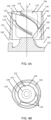
- Fig. 4A and 4B show the socket 110 as shown in Fig. 2 and 3 .
- the same reference symbols refer to the same features.
- the position of a burner 170 which is arranged in the interior 138 of the base 110, is also shown according to an example.
- the burner 170 extends essentially over a height of the interior 138 between the pedestal 124 and the opening 136.
- the burner 170 is also dimensioned such that an outer side of the burner 170 borders on the projections 116 in the region of a lateral surface of the burner 170, so that, as described above, air channels 130 are delimited.
- the burner 170 comprises a fuel reservoir 172 and a combustion opening 174 arranged on the top.
- the combustion opening 174 is provided so that when the burner 170 is in operation, fuel exits from the fuel reservoir 172 through the combustion opening 174 in order to feed a flame in a combustion zone above the burner 170. Due to the thermodynamic processes that occur when the burner 170 is in operation, in particular the rising of heated exhaust air in the casing 150, supply air that enters the base 110 through the air inlet openings 128 simultaneously passes upwards through the air ducts 130 into the region of the combustion zone above the burner 170.
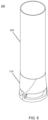
- Fig.5 shows a perspective view of the stand fire device 100.
- the casing 150 has a substantially tubular shape.
- a diameter of the casing 150 on an outer side at the lower end of the casing 150 corresponds to Example approximately a diameter of the base 110 at its top.
- the standing fire device 100 therefore has an overall column-like and essentially cylindrical shape, which is partially twisted due to the spiral-shaped decorative contours in the area of the base 110.
- the base 110 has a height in the range between 80 and 400 mm, preferably between 120 and 300 mm, preferably between 150 and 200 mm. In addition, in some examples, the base 110 has a largest diameter in the range between 60 and 500 mm, preferably between 103 and 100 mm, preferably between 120 and 200 mm.
- the base 110 also has a mass in the range between 0.5 and 12 kilograms, preferably between 1 and 5 kilograms, preferably between 1.5 and 3 kilograms.
- a relatively large mass of the base 110 promotes stability of the standing fire device 100.
- a relatively low mass of the base 110 promotes transportability and setting up of the standing fire device 100 on structures with low to medium load-bearing capacity, such as tables or window sills.
- Relatively large dimensions of the base 110 also favor an overall large design of the standing fire device 100. This favors, for example, an increased lighting and heating output of the standing fire device 100 as well as an enhanced aesthetic impression in spacious environments, especially outdoors. Relatively large dimensions of the base 110 also favor the inclusion of burners with a larger amount of fuel. In some examples, this favors a large flame and/or a long burning time before, for example, the burner needs to be refilled.
- Relatively small dimensions of the standing fire device 100 and the resulting smaller burners and smaller amounts of fuel favor the transportability of the standing fire device 100 as a whole and a reduced risk as a result of a quantity of fuel stored in the burner possibly leaking out of the burner and/or igniting uncontrollably.
- the casing 150 has a height in the range between 160 and 800 mm, preferably between 206 and 100 mm, preferably between 240 and 400 mm.
- the casing has a diameter in the range between 50 and 450 mm, preferably between 80 and 260 mm, preferably between 100 and 180 mm.
- the shell 150 also has a mass in the range between 0.2 and 5 kg, preferably between 0.5 and 3 kg, preferably between one and 2 kg.
- the standing fire device 100 when the shell 150, as in Fig.5 shown, arranged on the base 110, the standing fire device 100 has a total height of between 240 and 1200 mm, preferably between 320 and 900 mm, preferably between 360 and 600 mm.
- Examples of the standing fire device 100 with relatively large dimensions are particularly suitable for free-standing installation, especially outdoors. Relatively small dimensions, on the other hand, make the standing fire device 100 particularly suitable for installation on structures with low to medium load-bearing capacity, such as tables or window sills, and/or indoors.
- the standing fire device 100 has a substantially columnar, cylindrical, in particular tubular structure.
- all or some of the above-described advantages of a stand device 100 can also be achieved with other structures and designs that deviate from the forms shown, as well as with other materials and manufacturing methods than those described above.
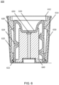
- Fig.6 shows schematically and by way of example a cross-sectional view of a casting mold 600 along a vertical center plane.
- the casting mold 600 is suitable for producing the base 110 of a standing fire device 100 according to the previous examples by means of casting.
- the mold 600 includes an outer mold 610, an inner mold 620, an outer support mold 630 and an inner support mold 640.
- the outer mold 610 and the inner mold 620 are in contact with each other in a connection region 622 to form a mold volume that is between the outer shape 610 and the inner shape 620 extends.
- the outer mold 610 has a mold opening 612 on its top, which is intended to enable the casting compound to be poured into the mold volume.
- the outer shape 610 has a contour on its inside, which essentially determines an outer shape of the base 110.
- Fig. 6 for example webs 614, which extend to the inner shape 620 and which are intended to form the air inlet areas 128.
- the inner shape 620 has a contour that essentially corresponds to a shape of the interior 138 of the base 110.
- Fig. 6 for example, trench-shaped depressions 622 on the outside. These are designed to form the projections 116.
- a central depression 626 can be seen on the top of the inner shape 620. This is designed to form the pedestal 124.
- the outer shape 610 and the inner shape 620 are preferably made of flexible material, for example silicone or polyurethane. This facilitates removal of the outer mold 610 and the inner mold 620 from the finished casting after casting and curing without damaging the inner mold 620 or the outer mold 610.
- the outer support mold 630 and the inner support mold 640 are provided to ensure a position of the, in particular flexible, outer and inner mold 610, 620 when the mold volume is filled with the liquid casting compound.
- the outer support mold 630 essentially supports a position of the outer mold 610.
- the inner support mold 640 essentially supports a position of the inner mold 620.
- the outer support mold 630 and the inner support mold 640 are detachably fastened to one another by means of a screw connection 650.
Landscapes
- Engineering & Computer Science (AREA)
- Chemical & Material Sciences (AREA)
- Combustion & Propulsion (AREA)
- Mechanical Engineering (AREA)
- General Engineering & Computer Science (AREA)
- Gas Burners (AREA)
Priority Applications (1)
| Application Number | Priority Date | Filing Date | Title |
|---|---|---|---|
| EP22199217.5A EP4345375A1 (fr) | 2022-09-30 | 2022-09-30 | Dispositif de tir au sol |
Applications Claiming Priority (1)
| Application Number | Priority Date | Filing Date | Title |
|---|---|---|---|
| EP22199217.5A EP4345375A1 (fr) | 2022-09-30 | 2022-09-30 | Dispositif de tir au sol |
Publications (1)
| Publication Number | Publication Date |
|---|---|
| EP4345375A1 true EP4345375A1 (fr) | 2024-04-03 |
Family
ID=83994929
Family Applications (1)
| Application Number | Title | Priority Date | Filing Date |
|---|---|---|---|
| EP22199217.5A Pending EP4345375A1 (fr) | 2022-09-30 | 2022-09-30 | Dispositif de tir au sol |
Country Status (1)
| Country | Link |
|---|---|
| EP (1) | EP4345375A1 (fr) |
Citations (6)
| Publication number | Priority date | Publication date | Assignee | Title |
|---|---|---|---|---|
| DE202007018478U1 (de) * | 2007-09-05 | 2008-09-11 | Rieger, Carsten | Gerät für eine Flammensäule |
| US20120178035A1 (en) | 2011-01-11 | 2012-07-12 | Wei-Long Chen | Device for Producing Stable and Augmented Flame |
| EP2886954A1 (fr) * | 2013-12-17 | 2015-06-24 | Pro-Iroda Industries, Inc. | Dispositif de flamme tourbillonnaire réglable pour une lampe à combustible liquide |
| CN105299739A (zh) * | 2015-12-09 | 2016-02-03 | 常州市威尔莱炉业有限公司 | 旋转火焰取暖器 |
| US20170336069A1 (en) * | 2016-03-11 | 2017-11-23 | Armando Parra | Spiral flame torch apparatus |
| DE202018004601U1 (de) | 2018-10-04 | 2019-10-10 | Thomas Kaiser | Feuersäule |
-
2022
- 2022-09-30 EP EP22199217.5A patent/EP4345375A1/fr active Pending
Patent Citations (6)
| Publication number | Priority date | Publication date | Assignee | Title |
|---|---|---|---|---|
| DE202007018478U1 (de) * | 2007-09-05 | 2008-09-11 | Rieger, Carsten | Gerät für eine Flammensäule |
| US20120178035A1 (en) | 2011-01-11 | 2012-07-12 | Wei-Long Chen | Device for Producing Stable and Augmented Flame |
| EP2886954A1 (fr) * | 2013-12-17 | 2015-06-24 | Pro-Iroda Industries, Inc. | Dispositif de flamme tourbillonnaire réglable pour une lampe à combustible liquide |
| CN105299739A (zh) * | 2015-12-09 | 2016-02-03 | 常州市威尔莱炉业有限公司 | 旋转火焰取暖器 |
| US20170336069A1 (en) * | 2016-03-11 | 2017-11-23 | Armando Parra | Spiral flame torch apparatus |
| DE202018004601U1 (de) | 2018-10-04 | 2019-10-10 | Thomas Kaiser | Feuersäule |
Similar Documents
| Publication | Publication Date | Title |
|---|---|---|
| DE60123957T2 (de) | Brenner mit interner trennung | |
| EP0725914B1 (fr) | Bougeoir | |
| EP3861254B1 (fr) | Colonne de feu | |
| DE2143520C3 (de) | Brenner zum Abfackeln von Gas | |
| WO1993016153A1 (fr) | Lampe a eclairage permanent | |
| EP2098781A2 (fr) | Dispositif de génération de flammes | |
| DE3302591A1 (de) | Kerzenstaender | |
| EP4345375A1 (fr) | Dispositif de tir au sol | |
| EP0268208A2 (fr) | Brûleur pour chaudière à combustible solide | |
| DE102021209245B4 (de) | Feuersäule mit Brennstoffbehälter und Brennstoffbehälter | |
| EP1484551A1 (fr) | Lampe | |
| DE202010000376U1 (de) | Brenner | |
| EP3686492B1 (fr) | Bac à flamme à gaz | |
| DE202011106037U1 (de) | Vorrichtung zum Verbrennen von Kerzenresten | |
| DE1961932A1 (de) | Gasbrenner | |
| DE2156374B2 (de) | Topfvergasungsbrenner fuer fluessigkeitsbrennstoff | |
| DE102010062181B4 (de) | Feuerungseinrichtung | |
| DE662767C (de) | Dochtgluehlichtbrenner | |
| DE2302775C3 (de) | Kerzenformiger Leuchtkörper, insbesondere zur Aufstellung in Kirchen, Kapellen, Gedenkstatten od.dgl | |
| EP1326052B1 (fr) | Poêle, en particulier cheminée | |
| DE2440546C2 (de) | Kerze | |
| DE10217676A1 (de) | Ofen, insbesondere Kamin | |
| DE2301265A1 (de) | Sparkerze mit einem aeusseren kerzenlaufrohr od. dgl. und einem eine einsatzkerze aufnehmenden einsatz | |
| DE158976C (fr) | ||
| AT306904B (de) | Kerze |
Legal Events
| Date | Code | Title | Description |
|---|---|---|---|
| PUAI | Public reference made under article 153(3) epc to a published international application that has entered the european phase |
Free format text: ORIGINAL CODE: 0009012 |
|
| STAA | Information on the status of an ep patent application or granted ep patent |
Free format text: STATUS: THE APPLICATION HAS BEEN PUBLISHED |
|
| AK | Designated contracting states |
Kind code of ref document: A1 Designated state(s): AL AT BE BG CH CY CZ DE DK EE ES FI FR GB GR HR HU IE IS IT LI LT LU LV MC MK MT NL NO PL PT RO RS SE SI SK SM TR |
|
| 19U | Interruption of proceedings before grant |
Effective date: 20230427 |
|
| 19W | Proceedings resumed before grant after interruption of proceedings |
Effective date: 20250502 |
|
| RAP3 | Party data changed (applicant data changed or rights of an application transferred) |
Owner name: BH DESIGNMANUFAKTUR GMBH |
|
| STAA | Information on the status of an ep patent application or granted ep patent |
Free format text: STATUS: REQUEST FOR EXAMINATION WAS MADE |
|
| 17P | Request for examination filed |
Effective date: 20251203 |
|
| 19U | Interruption of proceedings before grant |
Effective date: 20250723 |
|
| 19W | Proceedings resumed before grant after interruption of proceedings |
Effective date: 20260504 |