EP4345566B1 - Vorrichtung, system und verfahren zur verwendung von tiefenbeurteilung für autonome roboternavigation - Google Patents
Vorrichtung, system und verfahren zur verwendung von tiefenbeurteilung für autonome roboternavigation Download PDFInfo
- Publication number
- EP4345566B1 EP4345566B1 EP24157471.4A EP24157471A EP4345566B1 EP 4345566 B1 EP4345566 B1 EP 4345566B1 EP 24157471 A EP24157471 A EP 24157471A EP 4345566 B1 EP4345566 B1 EP 4345566B1
- Authority
- EP
- European Patent Office
- Prior art keywords
- robot
- depth camera
- dimensional depth
- view
- obstacles
- Prior art date
- Legal status (The legal status is an assumption and is not a legal conclusion. Google has not performed a legal analysis and makes no representation as to the accuracy of the status listed.)
- Active
Links
Images

Classifications
-
- G—PHYSICS
- G05—CONTROLLING; REGULATING
- G05D—SYSTEMS FOR CONTROLLING OR REGULATING NON-ELECTRIC VARIABLES
- G05D1/00—Control of position, course, altitude or attitude of land, water, air or space vehicles, e.g. using automatic pilots
- G05D1/02—Control of position or course in two dimensions
- G05D1/021—Control of position or course in two dimensions specially adapted to land vehicles
- G05D1/0231—Control of position or course in two dimensions specially adapted to land vehicles using optical position detecting means
- G05D1/0238—Control of position or course in two dimensions specially adapted to land vehicles using optical position detecting means using obstacle or wall sensors
-
- B—PERFORMING OPERATIONS; TRANSPORTING
- B25—HAND TOOLS; PORTABLE POWER-DRIVEN TOOLS; MANIPULATORS
- B25J—MANIPULATORS; CHAMBERS PROVIDED WITH MANIPULATION DEVICES
- B25J19/00—Accessories fitted to manipulators, e.g. for monitoring, for viewing; Safety devices combined with or specially adapted for use in connection with manipulators
- B25J19/02—Sensing devices
- B25J19/021—Optical sensing devices
- B25J19/023—Optical sensing devices including video camera means
-
- B—PERFORMING OPERATIONS; TRANSPORTING
- B25—HAND TOOLS; PORTABLE POWER-DRIVEN TOOLS; MANIPULATORS
- B25J—MANIPULATORS; CHAMBERS PROVIDED WITH MANIPULATION DEVICES
- B25J9/00—Program-controlled manipulators
- B25J9/16—Program controls
- B25J9/1656—Program controls characterised by programming, planning systems for manipulators
- B25J9/1664—Program controls characterised by programming, planning systems for manipulators characterised by motion, path, trajectory planning
- B25J9/1666—Avoiding collision or forbidden zones
-
- B—PERFORMING OPERATIONS; TRANSPORTING
- B25—HAND TOOLS; PORTABLE POWER-DRIVEN TOOLS; MANIPULATORS
- B25J—MANIPULATORS; CHAMBERS PROVIDED WITH MANIPULATION DEVICES
- B25J9/00—Program-controlled manipulators
- B25J9/16—Program controls
- B25J9/1674—Program controls characterised by safety, monitoring, diagnostic
- B25J9/1676—Avoiding collision or forbidden zones
-
- G—PHYSICS
- G05—CONTROLLING; REGULATING
- G05D—SYSTEMS FOR CONTROLLING OR REGULATING NON-ELECTRIC VARIABLES
- G05D1/00—Control of position, course, altitude or attitude of land, water, air or space vehicles, e.g. using automatic pilots
-
- G—PHYSICS
- G05—CONTROLLING; REGULATING
- G05D—SYSTEMS FOR CONTROLLING OR REGULATING NON-ELECTRIC VARIABLES
- G05D1/00—Control of position, course, altitude or attitude of land, water, air or space vehicles, e.g. using automatic pilots
- G05D1/02—Control of position or course in two dimensions
- G05D1/021—Control of position or course in two dimensions specially adapted to land vehicles
- G05D1/0231—Control of position or course in two dimensions specially adapted to land vehicles using optical position detecting means
- G05D1/0246—Control of position or course in two dimensions specially adapted to land vehicles using optical position detecting means using a video camera in combination with image processing means
-
- G—PHYSICS
- G05—CONTROLLING; REGULATING
- G05D—SYSTEMS FOR CONTROLLING OR REGULATING NON-ELECTRIC VARIABLES
- G05D1/00—Control of position, course, altitude or attitude of land, water, air or space vehicles, e.g. using automatic pilots
- G05D1/20—Control system inputs
-
- G—PHYSICS
- G05—CONTROLLING; REGULATING
- G05D—SYSTEMS FOR CONTROLLING OR REGULATING NON-ELECTRIC VARIABLES
- G05D1/00—Control of position, course, altitude or attitude of land, water, air or space vehicles, e.g. using automatic pilots
- G05D1/20—Control system inputs
- G05D1/22—Command input arrangements
-
- G—PHYSICS
- G05—CONTROLLING; REGULATING
- G05D—SYSTEMS FOR CONTROLLING OR REGULATING NON-ELECTRIC VARIABLES
- G05D1/00—Control of position, course, altitude or attitude of land, water, air or space vehicles, e.g. using automatic pilots
- G05D1/20—Control system inputs
- G05D1/24—Arrangements for determining position or orientation
- G05D1/243—Means capturing signals occurring naturally from the environment, e.g. ambient optical, acoustic, gravitational or magnetic signals
- G05D1/2435—Extracting 3D information
-
- G—PHYSICS
- G05—CONTROLLING; REGULATING
- G05D—SYSTEMS FOR CONTROLLING OR REGULATING NON-ELECTRIC VARIABLES
- G05D1/00—Control of position, course, altitude or attitude of land, water, air or space vehicles, e.g. using automatic pilots
- G05D1/20—Control system inputs
- G05D1/24—Arrangements for determining position or orientation
- G05D1/247—Arrangements for determining position or orientation using signals provided by artificial sources external to the vehicle, e.g. navigation beacons
- G05D1/249—Arrangements for determining position or orientation using signals provided by artificial sources external to the vehicle, e.g. navigation beacons from positioning sensors located off-board the vehicle, e.g. from cameras
-
- G—PHYSICS
- G05—CONTROLLING; REGULATING
- G05D—SYSTEMS FOR CONTROLLING OR REGULATING NON-ELECTRIC VARIABLES
- G05D1/00—Control of position, course, altitude or attitude of land, water, air or space vehicles, e.g. using automatic pilots
- G05D1/60—Intended control result
- G05D1/617—Safety or protection, e.g. defining protection zones around obstacles or avoiding hazards
- G05D1/622—Obstacle avoidance
- G05D1/628—Obstacle avoidance following the obstacle profile, e.g. a wall or undulated terrain
-
- G—PHYSICS
- G06—COMPUTING OR CALCULATING; COUNTING
- G06T—IMAGE DATA PROCESSING OR GENERATION, IN GENERAL
- G06T7/00—Image analysis
- G06T7/50—Depth or shape recovery
- G06T7/55—Depth or shape recovery from multiple images
- G06T7/593—Depth or shape recovery from multiple images from stereo images
-
- G—PHYSICS
- G06—COMPUTING OR CALCULATING; COUNTING
- G06V—IMAGE OR VIDEO RECOGNITION OR UNDERSTANDING
- G06V20/00—Scenes; Scene-specific elements
- G06V20/10—Terrestrial scenes
-
- G—PHYSICS
- G05—CONTROLLING; REGULATING
- G05D—SYSTEMS FOR CONTROLLING OR REGULATING NON-ELECTRIC VARIABLES
- G05D1/00—Control of position, course, altitude or attitude of land, water, air or space vehicles, e.g. using automatic pilots
- G05D1/02—Control of position or course in two dimensions
- G05D1/021—Control of position or course in two dimensions specially adapted to land vehicles
- G05D1/0231—Control of position or course in two dimensions specially adapted to land vehicles using optical position detecting means
- G05D1/0246—Control of position or course in two dimensions specially adapted to land vehicles using optical position detecting means using a video camera in combination with image processing means
- G05D1/0248—Control of position or course in two dimensions specially adapted to land vehicles using optical position detecting means using a video camera in combination with image processing means in combination with a laser
-
- G—PHYSICS
- G05—CONTROLLING; REGULATING
- G05D—SYSTEMS FOR CONTROLLING OR REGULATING NON-ELECTRIC VARIABLES
- G05D1/00—Control of position, course, altitude or attitude of land, water, air or space vehicles, e.g. using automatic pilots
- G05D1/20—Control system inputs
- G05D1/24—Arrangements for determining position or orientation
- G05D1/247—Arrangements for determining position or orientation using signals provided by artificial sources external to the vehicle, e.g. navigation beacons
-
- G—PHYSICS
- G06—COMPUTING OR CALCULATING; COUNTING
- G06T—IMAGE DATA PROCESSING OR GENERATION, IN GENERAL
- G06T2207/00—Indexing scheme for image analysis or image enhancement
- G06T2207/10—Image acquisition modality
- G06T2207/10028—Range image; Depth image; 3D point clouds
Definitions
- the invention relates generally to robotics, and, more particularly, to an apparatus, system, and method of using depth assessment for autonomous robot navigation.
- Indoor and outdoor autonomous vehicles are a category of robotics that is quickly advancing.
- indoor robotic vehicles are now available for a variety of purposes, including but not limited to cleaning, patrolling and inspecting, security, inventory management, patient movement, wheel chairs, personal assistants, item transport, research, hazardous materials handling, hazardous condition assessment, and so on.
- the invention is and includes at least an apparatus, system and method of operating an autonomous mobile robot.
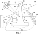
- the apparatus, system and method may include a robot body; a first three-dimensional depth camera sensor affixed to a first side of the robot body and a second three-dimensional depth camera sensor affixed to a second side of the robot body , wherein the at least two three-dimensional depth camera sensors are both directed toward a major floor surface from the affixation and, in combination, comprise an at least substantially 360 degree field of view of the major floor surface around the robot body; and a processing system communicative with the at least two three dimensional depth camera sensors and comprising non-transitory computing code.
- the first three-dimensional depth camera sensor is affixed proximate the height at a first angle of incidence relative to a major floor surface
- the second three-dimensional depth camera sensor affixed proximate to the height at a second angle of incidence relative to the major floor surface.
- the first three-dimensional depth camera sensor is affixed proximate to the height at a first angle of incidence relative to a major floor surface
- the second three-dimensional depth camera sensor affixed proximate to the height at a second angle of incidence relative to the major floor surface
- the first and second angle of incidence relative to the major floor surface comprises a predetermined angle related to the field of view.
- the first angle of incidence relative to the major floor surface comprises the first three-dimensional depth camera sensor directed along a first motion axis of the robot body and the second angle of incidence relative to the major floor surface comprises the second three-dimensional depth camera sensor directed along a second motion axis of the robot body.
- an inception point of a radius of the field of view is less than 20cm from the robot body.
- the inception point may be on the robot body.
- the processing system further comprises communication capabilities for transceiving at least part of the comparing.
- the templates comprises an average of a plurality of sample depth images taken by the first and second three-dimensional depth camera sensors when the robot is in an open space with no obstacles in the field of view.
- the missing or erroneous pixels are compared to a plurality of templates.
- the processing system may further comprise second non-transitory computing code for governing operation of the robot based on the indication.
- the governed operation may be selected from the group consisting of a full stop of motion, planning, environment mapping, and safety monitoring.
- the governed operation may comprise a maneuver precise to +/- 0.5cm.
- first, second, third, etc. may be used herein to describe various elements, components, regions, layers and/or sections, these elements, components, regions, layers and/or sections should not be limited by these terms. These terms may be only used to distinguish one element, component, region, layer or section from another element, component, region, layer or section. That is, terms such as “first,” “second,” and other numerical terms, when used herein, do not imply a sequence or order unless clearly indicated by the context. Thus, a first element, component, region, layer or section discussed below could be termed a second element, component, region, layer or section without departing from the teachings of the exemplary embodiments.
- modules, systems and methods of use are disclosed herein that may provide access to and transformation of a plurality of types of digital content, including but not limited to video, image, text, audio, metadata, algorithms, interactive and document content, and which track, deliver, manipulate, transform and report the accessed content.
- Described embodiments of these modules, systems and methods are intended to be exemplary and not limiting. As such, it is contemplated that the herein described systems and methods may be adapted and may be extended to provide enhancements and/or additions to the exemplary modules, systems and methods described. The invention is thus intended to include all such extensions.
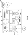
- a computer program product in accordance with one embodiment comprises a tangible computer usable medium (e.g., standard RAM, an optical disc, a USB drive, or the like) having computer-readable program code embodied therein, wherein the computer-readable program code is adapted to be executed by a processor (which may work in connection with an operating system) to implement one or more functions and methods as described below.
- a processor which may work in connection with an operating system
- program code may be implemented in any desired language, and may be implemented as machine code, assembly code, byte code, interpretable source code or the like (e.g., via C, C++, C#, Java, Actionscript, Objective-C, Javascript, CSS, XML, etc.).
- the invention provides a highly accurate apparatus, system and method for close-range obstacle avoidance and navigation by an autonomous robot. This may be achieved by the use of advantageous sensors and sensor arrangements as compared to the known art, and by the use of improved processing methodologies for the data provided by those sensors and sensor arrangements.
- the embodiments may provide a mobile robot having a substantially 360 degree field of view (FoV) for obstacle assessment.
- Embodiments may use as few as two depth cameras to provide this FoV, and the geometry and obstacle-assessment techniques provided enable rich amounts of information to be extracted from the depth data provided by the FoV sensors. More particularly, embodiments provide advantageous treatment of FoV data indicative of pixels in the FoV image(s) for which depth data is missing.
- This missing depth data may be indicative of an obstacle in sensor range, an obstacle out of sensor range, the shadow of an obstacle out of sensor range, the robot on which the sensors reside, or the shadow of the robot on which the sensors reside. Indicating something as an obstacle when it is not leads to poor path planning for the robot, and indicating a path as clear when there is an obstacle can lead to collisions or physical injuries.
- Embodiments provide improved assessment of the presence or absence of obstacles using missing pixel data, and may accordingly enable improved path planning and operational safety.
- the invention provides for disambiguation of the meaning of missing pixels within the FoV, providing highly valid obstacle detection in proximity to the robot.
- An additional prior solution may employ an array of infrared (IR) range finders.
- IR array may provide more precise distance measurements than an ultrasonic array, but can only detect obstacles that intersect the sensing ray at a specific angle from the robot.
- a prohibitively costly and great number of IR sensors would be required.
- this requirement that the ray be intersected at a substantially nonoblique angle makes IR sensing ill-equipped to locate slopes, cliffs, steps or holes.
- planar LIDAR provides a very precise distance and direction measurement, but only if an obstacle intersects the plane that the LIDAR sweeps. This means that the LIDAR must be mounted high enough to avoid false floor returns, and this high mounting requirement limits its ability to detect small or short obstacles. Thus, in order to detect obstacles that are much shorter than the robot, multiple LIDARs would be required to get 360-degree coverage; and, given that each LIDAR sensor costs several thousand dollars, the need for an array of planar LIDAR sensors would add prohibitively to the robot's cost.
- planar LIDAR because it senses in-plane, is unable to detect stairs, holes or cliffs. Yet further, because planar LIDAR operates in-plane, when approaching an upward slope, planar LIDAR may not detect the slope as an obstacle, or may detect a gentle slope as an obstacle, depending on the height of the sensor. If a significant slope in the floor is not timely detected, the robot may attempt to ascend a slope that is beyond its operating limitations, and if a gentle slope is detected as significant, operation may cease improperly.
- a tilting planar LIDAR scanner is capable of achieving a very detailed view of up to three sides of the robot.
- at least two tilting planar LIDAR scanners are required to get a 360-degree view around the robot for larger robots, and, at a cost appreciably greater than a planar LIDAR scanner, the need for two tilting planar LIDAR scanners make this option prohibitively expensive.
- a tilting planar LIDAR can detect slopes, cliffs, holes and steps, it suffers from an exceedingly slow scanning rate of about 1 Hz. Consequently, this sensor type is very slow to respond to dynamic obstacles, thus making it unsafe for an environment in which living creatures that move about are also present.
- a 3D depth camera oriented horizontally, has been used for obstacle avoidance in the known art.
- this sensor is oriented horizontally, it provides only a very limited field of view in the range of 60 to 90 degrees, and is further unable to see very short obstacles in the immediate vicinity of the robot but below the horizon of the sensor.
- a 3D depth camera is mounted low on the front of the robot to address the foregoing issues, it must be angled downward toward the floor and thus provides only a very limited view of what is directly in front of the robot.
- an "obstacle” may include any raised element, raised item, or raised or sloped part of the floor that extends above the plane provided by the immediately adjacent major floor surface; or any floor portion having a slope or lower portion that has a height below the plane provided by the immediately adjacent major floor surface.
Landscapes
- Engineering & Computer Science (AREA)
- Physics & Mathematics (AREA)
- General Physics & Mathematics (AREA)
- Remote Sensing (AREA)
- Automation & Control Theory (AREA)
- Aviation & Aerospace Engineering (AREA)
- Radar, Positioning & Navigation (AREA)
- Multimedia (AREA)
- Robotics (AREA)
- Mechanical Engineering (AREA)
- Theoretical Computer Science (AREA)
- Computer Vision & Pattern Recognition (AREA)
- Electromagnetism (AREA)
- Optics & Photonics (AREA)
- Control Of Position, Course, Altitude, Or Attitude Of Moving Bodies (AREA)
Claims (15)
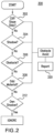
- Autonomer mobiler Roboter (106), umfassend:einen Roboterkörper;einen ersten dreidimensionalen Tiefenkamerasensor (102), der an einer ersten Seite des Roboterkörpers befestigt ist;einen zweiten dreidimensionalen Tiefenkamerasensor (104), der an einer zweiten Seite des Roboterkörpers befestigt ist;wobei die ersten und zweiten dreidimensionalen Tiefenkamerasensoren (102, 104) in Kombination ein mindestens 360 Grad umfassendes Sichtfeld (108) einer Hauptbodenfläche (110) um den Roboterkörper herum umfassen; undein Verarbeitungssystem (120), das mit dem ersten und dem zweiten dreidimensionalen Tiefenkamerasensor (102, 104) kommuniziert und einen nichttransitorischen Rechencode umfasst, der, wenn er von mindestens einem mit dem Verarbeitungssystem (120) verbundenen Prozessor (410) ausgeführt wird, die Ausführung der folgenden Schritte bewirkt:Empfangen von Pixeldaten (170) innerhalb des Sichtfeldes (108) von den ersten und zweiten dreidimensionalen Tiefenkamerasensoren (102, 104);Erhalten von fehlenden oder fehlerhaften Pixeln (170a) aus den Pixeldaten (170);Vergleichen der fehlenden oder fehlerhaften Pixel (170a) mit mindestens einer Vorlage, wobei die mindestens eine Vorlage mindestens eine Angabe von einen den fehlenden oder fehlerhaften Pixeln (170a) umfasst, die den Roboterkörper und einen Schatten (106b) des Roboterkörpers anzeigen; undAusgeben einer Anzeige von Hindernissen (160, 162, 164) im oder in der Nähe des Sichtfeldes (108) basierend auf dem Vergleich.
- Roboter nach Anspruch 1, wobei der erste dreidimensionale Tiefenkamerasensor (102) in der Nähe einer Höhe des Roboterkörpers in einem ersten Einfallswinkel relativ zu der Hauptbodenfläche (110) befestigt ist, der zweite dreidimensionale Tiefenkamerasensor (104) in der Nähe der Höhe in einem zweiten Einfallswinkel relativ zu der Hauptbodenfläche (110) befestigt ist, und wobei der erste und der zweite Einfallswinkel relativ zu der Hauptbodenfläche (110) einen vorbestimmten Winkel in Bezug auf das Sichtfeld (108) umfassen.
- Roboter nach Anspruch 2, wobei der erste Einfallswinkel relativ zu der Hauptbodenfläche (110) den ersten dreidimensionalen Tiefenkamerasensor (102) umfasst, der entlang einer ersten Bewegungsachse des Roboterkörpers ausgerichtet ist, und der zweite Einfallswinkel relativ zu der Hauptbodenfläche (110) den zweiten dreidimensionalen Tiefenkamerasensor (104) umfasst, der entlang einer zweiten Bewegungsachse des Roboterkörpers ausgerichtet ist.
- Roboter nach Anspruch 1, wobei das Sichtfeld (108) einen Radius von mindestens zwei Metern umfasst.
- Roboter nach Anspruch 1, wobei ein Anfangspunkt eines Radius des Sichtfeldes (108) weniger als 20 cm vom Roboterkörper entfernt ist.
- Roboter nach Anspruch 5, wobei sich der Anfangspunkt auf dem Roboterkörper befindet.
- Roboter nach Anspruch 1, wobei der erste und der zweite dreidimensionale Tiefenkamerasensor (102, 104) drehbar sind, um das 360-Grad-Sichtfeld (108) zu erzeugen.
- Roboter nach Anspruch 1, wobei die Hindernisse (160, 162, 164) eine Höhe von mindestens 2 cm aufweisen.
- Roboter nach Anspruch 1, wobei die Hindernisse (160, 162, 164) aus der Gruppe ausgewählt sind, die aus einer Stufe, einem Abhang, einer Klippe, einem Loch und einem Schatten besteht.
- Roboter nach Anspruch 1, wobei die erste und die zweite dreidimensionale Tiefenkamera (102, 104) eine Bildrate zwischen 15 und 90 Bildern pro Sekunde aufweisen.
- Roboter nach Anspruch 1, wobei das Verarbeitungssystem (120) ferner Kommunikationsfähigkeiten (470, 480) zum Senden und Empfangen mindestens eines Teils des Vergleichs umfasst.
- Roboter nach Anspruch 1, wobei das Verarbeitungssystem (120) ferner Kommunikationsfähigkeiten (470, 480) zum Senden und Empfangen zumindest der Anzeige von Hindernissen (160, 162, 164) umfasst.
- Roboter nach Anspruch 1, wobei die Vorlagen einen Durchschnitt aus einer Vielzahl von Beispieltiefenbildern umfassen, die von den ersten und zweiten dreidimensionalen Tiefenkamerasensoren (102, 104) aufgenommen wurden, wenn sich der Roboter (106) in einem offenen Raum ohne Hindernisse (160, 162, 164) im Sichtfeld (108) befindet.
- Roboter nach Anspruch 1, wobei die fehlenden oder fehlerhaften Pixel (170a) mit einer Vielzahl von Vorlagen verglichen werden.
- Roboter nach Anspruch 1, wobei das Verarbeitungssystem (120) ferner einen zweiten, nichttransitorischen Rechencode umfasst, um den Betrieb des Roboters (106) basierend auf der Anzeige zu steuern.
Applications Claiming Priority (3)
| Application Number | Priority Date | Filing Date | Title |
|---|---|---|---|
| US201862648005P | 2018-03-26 | 2018-03-26 | |
| EP19776795.7A EP3776128B1 (de) | 2018-03-26 | 2019-03-26 | Vorrichtung, system und verfahren zur verwendung von tiefenbewertung für autonome roboternavigation |
| PCT/US2019/023981 WO2019191029A1 (en) | 2018-03-26 | 2019-03-26 | Apparatus, system, and method of using depth assessment for autonomous robot navigation |
Related Parent Applications (1)
| Application Number | Title | Priority Date | Filing Date |
|---|---|---|---|
| EP19776795.7A Division EP3776128B1 (de) | 2018-03-26 | 2019-03-26 | Vorrichtung, system und verfahren zur verwendung von tiefenbewertung für autonome roboternavigation |
Publications (3)
| Publication Number | Publication Date |
|---|---|
| EP4345566A2 EP4345566A2 (de) | 2024-04-03 |
| EP4345566A3 EP4345566A3 (de) | 2024-06-26 |
| EP4345566B1 true EP4345566B1 (de) | 2025-07-09 |
Family
ID=68060724
Family Applications (2)
| Application Number | Title | Priority Date | Filing Date |
|---|---|---|---|
| EP19776795.7A Active EP3776128B1 (de) | 2018-03-26 | 2019-03-26 | Vorrichtung, system und verfahren zur verwendung von tiefenbewertung für autonome roboternavigation |
| EP24157471.4A Active EP4345566B1 (de) | 2018-03-26 | 2019-03-26 | Vorrichtung, system und verfahren zur verwendung von tiefenbeurteilung für autonome roboternavigation |
Family Applications Before (1)
| Application Number | Title | Priority Date | Filing Date |
|---|---|---|---|
| EP19776795.7A Active EP3776128B1 (de) | 2018-03-26 | 2019-03-26 | Vorrichtung, system und verfahren zur verwendung von tiefenbewertung für autonome roboternavigation |
Country Status (4)
| Country | Link |
|---|---|
| US (3) | US12019452B2 (de) |
| EP (2) | EP3776128B1 (de) |
| CN (1) | CN112020688B (de) |
| WO (1) | WO2019191029A1 (de) |
Families Citing this family (20)
| Publication number | Priority date | Publication date | Assignee | Title |
|---|---|---|---|---|
| CN115279558A (zh) * | 2020-02-13 | 2022-11-01 | 捷普有限公司 | 用于自主机器人的相控阵天线的装置、系统和方法 |
| WO2021185805A2 (en) | 2020-03-18 | 2021-09-23 | Teknologisk Institut | A relocatable robotic system for production facilities |
| WO2021231996A1 (en) * | 2020-05-15 | 2021-11-18 | Brain Corporation | Systems and methods for detecting glass and specular surfaces for robots |
| US12080013B2 (en) * | 2020-07-06 | 2024-09-03 | Toyota Research Institute, Inc. | Multi-view depth estimation leveraging offline structure-from-motion |
| CA3196537A1 (en) * | 2020-10-24 | 2022-04-28 | Ajay VISHNU | Spatial blind spot monitoring systems and related methods of use |
| JP7707617B2 (ja) * | 2021-04-06 | 2025-07-15 | オムロン株式会社 | 床面状態検出装置およびこれを備えた測距装置、床面状態検出方法、床面状態検出プログラム |
| CN113341978B (zh) * | 2021-06-10 | 2023-03-07 | 西北工业大学 | 一种基于梯型障碍物的智能小车路径规划方法 |
| KR20230036447A (ko) * | 2021-09-07 | 2023-03-14 | 삼성전자주식회사 | 로봇 및 그 제어 방법 |
| EP4309856A4 (de) | 2021-09-07 | 2024-09-04 | Samsung Electronics Co., Ltd. | Roboter und verfahren zur steuerung davon |
| TWI782709B (zh) * | 2021-09-16 | 2022-11-01 | 財團法人金屬工業研究發展中心 | 手術機械臂控制系統以及手術機械臂控制方法 |
| DE102021210750B3 (de) * | 2021-09-27 | 2022-08-04 | OPTIMA pharma GmbH | Verfahren und Vorrichtung zur Behebung von Störungen in einer Füll- und/oder Verschließ- und/oder Nachverarbeitungsanlage |
| CN114199235B (zh) * | 2021-11-29 | 2023-11-03 | 珠海一微半导体股份有限公司 | 一种基于扇面深度相机的定位系统及定位方法 |
| CN114905506A (zh) * | 2022-04-15 | 2022-08-16 | 北京航空航天大学杭州创新研究院 | 一种基于视觉感知和空间认知神经机制的机器人导航系统 |
| US12449546B2 (en) * | 2022-04-15 | 2025-10-21 | Zebra Technologies Corporation | Lidar sensor system for enabling or disabling use of a robotic arm |
| CN115170797A (zh) * | 2022-06-01 | 2022-10-11 | 杭州海康机器人技术有限公司 | 一种移动机器人的控制方法和装置 |
| CN115783056B (zh) * | 2022-11-25 | 2026-04-03 | 宇树科技股份有限公司 | 一种移动机器人 |
| CN116000892A (zh) * | 2022-12-16 | 2023-04-25 | 南京机灵侠软件技术有限公司 | 一种机器人区分坡道与障碍及沟壑的方法 |
| CN116787421B (zh) * | 2022-12-21 | 2025-08-05 | 慧之安信息技术股份有限公司 | 用于野外场景的勘测机器人运动控制方法和系统 |
| CN116704493B (zh) * | 2023-05-30 | 2025-12-30 | 山东新一代信息产业技术研究院有限公司 | 基于机器人深度相机的障碍物检测系统及方法 |
| CN117824662B (zh) * | 2024-02-29 | 2024-05-28 | 锐驰激光(深圳)有限公司 | 机器人路径规划方法、装置、设备及存储介质 |
Family Cites Families (43)
| Publication number | Priority date | Publication date | Assignee | Title |
|---|---|---|---|---|
| US6107637A (en) * | 1997-08-11 | 2000-08-22 | Hitachi, Ltd. | Electron beam exposure or system inspection or measurement apparatus and its method and height detection apparatus |
| US8788092B2 (en) * | 2000-01-24 | 2014-07-22 | Irobot Corporation | Obstacle following sensor scheme for a mobile robot |
| US6975410B1 (en) * | 2002-04-15 | 2005-12-13 | Sturgill Dennis T | Measuring device |
| JP3875988B2 (ja) * | 2002-05-10 | 2007-01-31 | 本田技研工業株式会社 | 未知の障害物の中の予測不可能な目標物の実時間追跡 |
| US7263209B2 (en) | 2003-06-13 | 2007-08-28 | Sarnoff Corporation | Vehicular vision system |
| US9002511B1 (en) * | 2005-10-21 | 2015-04-07 | Irobot Corporation | Methods and systems for obstacle detection using structured light |
| US8577538B2 (en) | 2006-07-14 | 2013-11-05 | Irobot Corporation | Method and system for controlling a remote vehicle |
| JP4309920B2 (ja) * | 2007-01-29 | 2009-08-05 | 株式会社東芝 | 車載用ナビゲーション装置、路面標示識別プログラム及び路面標示識別方法 |
| US20090290019A1 (en) * | 2008-02-25 | 2009-11-26 | Aai Corporation | System, method and computer program product for integration of sensor and weapon systems with a graphical user interface |
| JP2009279663A (ja) | 2008-05-19 | 2009-12-03 | Kawada Kogyo Kk | ロボット用位置同定方法および装置 |
| CN102149596B (zh) * | 2008-09-11 | 2013-06-05 | 丰田自动车株式会社 | 移动体及其控制方法 |
| JP5518579B2 (ja) * | 2010-06-02 | 2014-06-11 | 本田技研工業株式会社 | 移動可能領域抽出装置および移動可能領域抽出方法 |
| US9440356B2 (en) * | 2012-12-21 | 2016-09-13 | Crosswing Inc. | Customizable robotic system |
| US9773285B2 (en) * | 2011-03-08 | 2017-09-26 | Bank Of America Corporation | Providing data associated with relationships between individuals and images |
| US20140327733A1 (en) * | 2012-03-20 | 2014-11-06 | David Wagreich | Image monitoring and display from unmanned vehicle |
| EP2834048B1 (de) * | 2012-09-21 | 2017-11-01 | iRobot Corporation | Näherungsmessung auf mobilen robotern |
| US11281207B2 (en) * | 2013-03-19 | 2022-03-22 | Robotic Research Opco, Llc | Delayed telop aid |
| US9037396B2 (en) * | 2013-05-23 | 2015-05-19 | Irobot Corporation | Simultaneous localization and mapping for a mobile robot |
| US9785911B2 (en) | 2013-07-25 | 2017-10-10 | I AM Robotics, LLC | System and method for piece-picking or put-away with a mobile manipulation robot |
| CN105899112B (zh) * | 2014-01-10 | 2018-07-06 | 艾罗伯特公司 | 自主移动机器人 |
| US20150336575A1 (en) * | 2014-05-21 | 2015-11-26 | GM Global Technology Operations LLC | Collision avoidance with static targets in narrow spaces |
| JP6132452B2 (ja) * | 2014-05-30 | 2017-05-24 | 株式会社日立国際電気 | 無線通信装置及び無線通信システム |
| US20160259982A1 (en) * | 2015-03-07 | 2016-09-08 | Mrs. Kavitha Kodinagenahalli Shivanandaiah | Vehicle view monitoring system |
| US9840003B2 (en) * | 2015-06-24 | 2017-12-12 | Brain Corporation | Apparatus and methods for safe navigation of robotic devices |
| WO2017047688A1 (ja) * | 2015-09-17 | 2017-03-23 | 株式会社日立国際電気 | 落下物検知追跡システム |
| KR102656197B1 (ko) * | 2015-11-18 | 2024-04-09 | 삼성전자주식회사 | 이동체, 로봇 청소기, 바닥 상태 판단 장치, 상기 이동체의 제어 방법 및 상기 로봇 청소기의 제어 방법 |
| US20170186223A1 (en) | 2015-12-23 | 2017-06-29 | Intel Corporation | Detection of shadow regions in image depth data caused by multiple image sensors |
| CN108235702B (zh) * | 2016-10-09 | 2022-01-14 | 深圳市道通智能航空技术股份有限公司 | 一种云台、无人机及其控制方法 |
| US9843858B1 (en) * | 2016-10-18 | 2017-12-12 | The United States Of America, As Represented By The Secretary Of The Navy | Direction finding system using MEMS sound sensors |
| JP7183155B2 (ja) * | 2016-11-02 | 2022-12-05 | コーニング インコーポレイテッド | 透明基板上の欠陥部検査方法および装置 |
| US10803324B1 (en) * | 2017-01-03 | 2020-10-13 | Waylens, Inc. | Adaptive, self-evolving learning and testing platform for self-driving and real-time map construction |
| JP6790998B2 (ja) * | 2017-04-28 | 2020-11-25 | 株式会社Soken | 障害物検知装置および制御装置 |
| CN109033951B (zh) * | 2017-06-12 | 2022-05-27 | 法拉第未来公司 | 用于基于图形处理来检测遮挡对象的系统及方法 |
| EP3642683B1 (de) * | 2017-06-22 | 2022-12-14 | Agjunction LLC | 3d-bildsystem zur fahrzeugsteuerung |
| JP6720931B2 (ja) * | 2017-07-14 | 2020-07-08 | 株式会社デンソー | 車両周囲認識装置 |
| US10915114B2 (en) * | 2017-07-27 | 2021-02-09 | AI Incorporated | Method and apparatus for combining data to construct a floor plan |
| EP3677977A4 (de) * | 2017-08-30 | 2021-06-02 | Positec Power Tools (Suzhou) Co., Ltd | Selbstbewegliche vorrichtung und steuerungsverfahren für bewegungsweg davon |
| CN107656545A (zh) | 2017-09-12 | 2018-02-02 | 武汉大学 | 一种面向无人机野外搜救的自主避障与导航方法 |
| US10691962B2 (en) * | 2017-09-22 | 2020-06-23 | Toyota Motor Engineering & Manufacturing North America, Inc. | Systems and methods for rear signal identification using machine learning |
| JP7135081B2 (ja) * | 2017-09-28 | 2022-09-12 | ソニーセミコンダクタソリューションズ株式会社 | 装置および方法 |
| JP6958252B2 (ja) * | 2017-11-07 | 2021-11-02 | トヨタ自動車株式会社 | 遠隔監視システム及び自律走行車両並びに遠隔監視方法 |
| CL2017003463A1 (es) * | 2017-12-28 | 2019-10-11 | Univ Pontificia Catolica Chile | Sistema robótico autónomo para el monitoreo automático del estado de estanterías en tiendas |
| US20190246858A1 (en) * | 2018-02-13 | 2019-08-15 | Nir Karasikov | Cleaning robot with arm and tool receptacles |
-
2019
- 2019-03-26 CN CN201980028502.6A patent/CN112020688B/zh active Active
- 2019-03-26 WO PCT/US2019/023981 patent/WO2019191029A1/en not_active Ceased
- 2019-03-26 EP EP19776795.7A patent/EP3776128B1/de active Active
- 2019-03-26 EP EP24157471.4A patent/EP4345566B1/de active Active
- 2019-03-26 US US17/042,840 patent/US12019452B2/en active Active
-
2024
- 2024-05-17 US US18/667,289 patent/US12422853B2/en active Active
-
2025
- 2025-08-14 US US19/299,580 patent/US20250370455A1/en active Pending
Also Published As
| Publication number | Publication date |
|---|---|
| EP3776128A4 (de) | 2021-11-10 |
| US20210026368A1 (en) | 2021-01-28 |
| EP4345566A3 (de) | 2024-06-26 |
| US20250370455A1 (en) | 2025-12-04 |
| US12422853B2 (en) | 2025-09-23 |
| EP3776128A1 (de) | 2021-02-17 |
| CN112020688B (zh) | 2024-06-11 |
| EP3776128B1 (de) | 2024-02-21 |
| EP4345566A2 (de) | 2024-04-03 |
| US12019452B2 (en) | 2024-06-25 |
| CN112020688A (zh) | 2020-12-01 |
| US20240370020A1 (en) | 2024-11-07 |
| WO2019191029A1 (en) | 2019-10-03 |
Similar Documents
| Publication | Publication Date | Title |
|---|---|---|
| US12422853B2 (en) | Apparatus, system, and method of using depth assessment for autonomous robot navigation | |
| US12505925B2 (en) | Interfacing with a mobile telepresence robot | |
| US8897947B2 (en) | Autonomous mobile device | |
| JP6949107B2 (ja) | 経路を自律走行するようにロボットを訓練するためのシステムおよび方法 | |
| CN109991589A (zh) | 扫描角度调整装置、激光雷达系统、载具及自动校正方法 | |
| JP2017016359A (ja) | 自律移動ロボット | |
| JP6595284B2 (ja) | 自律移動ロボット | |
| EP3802016B1 (de) | Andockvorrichtung, -system und -verfahren für autonome roboternavigation | |
| US10343603B2 (en) | Image processing device and image processing method | |
| JP7618378B2 (ja) | 自律移動体 | |
| US20250371726A1 (en) | Electronic device, control method, and control program | |
| KR20230090034A (ko) | 다종 광시야각 라이다 센서를 탑재한 무사각 전방향 감지 모바일 로봇 시스템 | |
| CN114663754A (zh) | 检测方法、装置、多足机器人及存储介质 | |
| CN114415659B (zh) | 一种机器人安全避障方法、装置、机器人及存储介质 | |
| JP7786826B2 (ja) | 情報処理装置、移動体、情報処理方法、及びコンピュータプログラム | |
| EP4501549B1 (de) | Robotervorrichtung, die in einem modus entsprechend der position der robotervorrichtung arbeitet, und steuerungsverfahren dafür |
Legal Events
| Date | Code | Title | Description |
|---|---|---|---|
| PUAI | Public reference made under article 153(3) epc to a published international application that has entered the european phase |
Free format text: ORIGINAL CODE: 0009012 |
|
| STAA | Information on the status of an ep patent application or granted ep patent |
Free format text: STATUS: THE APPLICATION HAS BEEN PUBLISHED |
|
| AC | Divisional application: reference to earlier application |
Ref document number: 3776128 Country of ref document: EP Kind code of ref document: P |
|
| AK | Designated contracting states |
Kind code of ref document: A2 Designated state(s): AL AT BE BG CH CY CZ DE DK EE ES FI FR GB GR HR HU IE IS IT LI LT LU LV MC MK MT NL NO PL PT RO RS SE SI SK SM TR |
|
| REG | Reference to a national code |
Ref country code: DE Ref legal event code: R079 Free format text: PREVIOUS MAIN CLASS: G05D0001000000 Ipc: B25J0009160000 Ref country code: DE Ref legal event code: R079 Ref document number: 602019072530 Country of ref document: DE Free format text: PREVIOUS MAIN CLASS: G05D0001000000 Ipc: B25J0009160000 |
|
| PUAL | Search report despatched |
Free format text: ORIGINAL CODE: 0009013 |
|
| AK | Designated contracting states |
Kind code of ref document: A3 Designated state(s): AL AT BE BG CH CY CZ DE DK EE ES FI FR GB GR HR HU IE IS IT LI LT LU LV MC MK MT NL NO PL PT RO RS SE SI SK SM TR |
|
| RIC1 | Information provided on ipc code assigned before grant |
Ipc: G06V 20/10 20220101ALI20240517BHEP Ipc: G05D 1/00 20240101ALI20240517BHEP Ipc: B25J 19/04 20060101ALI20240517BHEP Ipc: B25J 9/16 20060101AFI20240517BHEP |
|
| STAA | Information on the status of an ep patent application or granted ep patent |
Free format text: STATUS: REQUEST FOR EXAMINATION WAS MADE |
|
| 17P | Request for examination filed |
Effective date: 20240904 |
|
| RBV | Designated contracting states (corrected) |
Designated state(s): AL AT BE BG CH CY CZ DE DK EE ES FI FR GB GR HR HU IE IS IT LI LT LU LV MC MK MT NL NO PL PT RO RS SE SI SK SM TR |
|
| GRAP | Despatch of communication of intention to grant a patent |
Free format text: ORIGINAL CODE: EPIDOSNIGR1 |
|
| STAA | Information on the status of an ep patent application or granted ep patent |
Free format text: STATUS: GRANT OF PATENT IS INTENDED |
|
| INTG | Intention to grant announced |
Effective date: 20250211 |
|
| GRAS | Grant fee paid |
Free format text: ORIGINAL CODE: EPIDOSNIGR3 |
|
| GRAA | (expected) grant |
Free format text: ORIGINAL CODE: 0009210 |
|
| STAA | Information on the status of an ep patent application or granted ep patent |
Free format text: STATUS: THE PATENT HAS BEEN GRANTED |
|
| AC | Divisional application: reference to earlier application |
Ref document number: 3776128 Country of ref document: EP Kind code of ref document: P |
|
| AK | Designated contracting states |
Kind code of ref document: B1 Designated state(s): AL AT BE BG CH CY CZ DE DK EE ES FI FR GB GR HR HU IE IS IT LI LT LU LV MC MK MT NL NO PL PT RO RS SE SI SK SM TR |
|
| REG | Reference to a national code |
Ref country code: GB Ref legal event code: FG4D |
|
| REG | Reference to a national code |
Ref country code: CH Ref legal event code: EP |
|
| P01 | Opt-out of the competence of the unified patent court (upc) registered |
Free format text: CASE NUMBER: APP_30082/2025 Effective date: 20250624 |
|
| REG | Reference to a national code |
Ref country code: IE Ref legal event code: FG4D |
|
| REG | Reference to a national code |
Ref country code: DE Ref legal event code: R096 Ref document number: 602019072530 Country of ref document: DE |
|
| REG | Reference to a national code |
Ref country code: NL Ref legal event code: MP Effective date: 20250709 |
|
| PG25 | Lapsed in a contracting state [announced via postgrant information from national office to epo] |
Ref country code: PT Free format text: LAPSE BECAUSE OF FAILURE TO SUBMIT A TRANSLATION OF THE DESCRIPTION OR TO PAY THE FEE WITHIN THE PRESCRIBED TIME-LIMIT Effective date: 20251110 |
|
| PG25 | Lapsed in a contracting state [announced via postgrant information from national office to epo] |
Ref country code: NL Free format text: LAPSE BECAUSE OF FAILURE TO SUBMIT A TRANSLATION OF THE DESCRIPTION OR TO PAY THE FEE WITHIN THE PRESCRIBED TIME-LIMIT Effective date: 20250709 |
|
| REG | Reference to a national code |
Ref country code: AT Ref legal event code: MK05 Ref document number: 1811436 Country of ref document: AT Kind code of ref document: T Effective date: 20250709 |
|
| PG25 | Lapsed in a contracting state [announced via postgrant information from national office to epo] |
Ref country code: IS Free format text: LAPSE BECAUSE OF FAILURE TO SUBMIT A TRANSLATION OF THE DESCRIPTION OR TO PAY THE FEE WITHIN THE PRESCRIBED TIME-LIMIT Effective date: 20251109 |
|
| PG25 | Lapsed in a contracting state [announced via postgrant information from national office to epo] |
Ref country code: NO Free format text: LAPSE BECAUSE OF FAILURE TO SUBMIT A TRANSLATION OF THE DESCRIPTION OR TO PAY THE FEE WITHIN THE PRESCRIBED TIME-LIMIT Effective date: 20251009 |
|
| REG | Reference to a national code |
Ref country code: LT Ref legal event code: MG9D |
|
| PG25 | Lapsed in a contracting state [announced via postgrant information from national office to epo] |
Ref country code: AT Free format text: LAPSE BECAUSE OF FAILURE TO SUBMIT A TRANSLATION OF THE DESCRIPTION OR TO PAY THE FEE WITHIN THE PRESCRIBED TIME-LIMIT Effective date: 20250709 |
|
| PG25 | Lapsed in a contracting state [announced via postgrant information from national office to epo] |
Ref country code: FI Free format text: LAPSE BECAUSE OF FAILURE TO SUBMIT A TRANSLATION OF THE DESCRIPTION OR TO PAY THE FEE WITHIN THE PRESCRIBED TIME-LIMIT Effective date: 20250709 |
|
| PG25 | Lapsed in a contracting state [announced via postgrant information from national office to epo] |
Ref country code: HR Free format text: LAPSE BECAUSE OF FAILURE TO SUBMIT A TRANSLATION OF THE DESCRIPTION OR TO PAY THE FEE WITHIN THE PRESCRIBED TIME-LIMIT Effective date: 20250709 |
|
| PG25 | Lapsed in a contracting state [announced via postgrant information from national office to epo] |
Ref country code: GR Free format text: LAPSE BECAUSE OF FAILURE TO SUBMIT A TRANSLATION OF THE DESCRIPTION OR TO PAY THE FEE WITHIN THE PRESCRIBED TIME-LIMIT Effective date: 20251010 |
|
| PG25 | Lapsed in a contracting state [announced via postgrant information from national office to epo] |
Ref country code: SE Free format text: LAPSE BECAUSE OF FAILURE TO SUBMIT A TRANSLATION OF THE DESCRIPTION OR TO PAY THE FEE WITHIN THE PRESCRIBED TIME-LIMIT Effective date: 20250709 |
|
| PG25 | Lapsed in a contracting state [announced via postgrant information from national office to epo] |
Ref country code: LV Free format text: LAPSE BECAUSE OF FAILURE TO SUBMIT A TRANSLATION OF THE DESCRIPTION OR TO PAY THE FEE WITHIN THE PRESCRIBED TIME-LIMIT Effective date: 20250709 |
|
| PG25 | Lapsed in a contracting state [announced via postgrant information from national office to epo] |
Ref country code: BG Free format text: LAPSE BECAUSE OF FAILURE TO SUBMIT A TRANSLATION OF THE DESCRIPTION OR TO PAY THE FEE WITHIN THE PRESCRIBED TIME-LIMIT Effective date: 20250709 Ref country code: PL Free format text: LAPSE BECAUSE OF FAILURE TO SUBMIT A TRANSLATION OF THE DESCRIPTION OR TO PAY THE FEE WITHIN THE PRESCRIBED TIME-LIMIT Effective date: 20250709 |
|
| PG25 | Lapsed in a contracting state [announced via postgrant information from national office to epo] |
Ref country code: RS Free format text: LAPSE BECAUSE OF FAILURE TO SUBMIT A TRANSLATION OF THE DESCRIPTION OR TO PAY THE FEE WITHIN THE PRESCRIBED TIME-LIMIT Effective date: 20251009 |
|
| PG25 | Lapsed in a contracting state [announced via postgrant information from national office to epo] |
Ref country code: ES Free format text: LAPSE BECAUSE OF FAILURE TO SUBMIT A TRANSLATION OF THE DESCRIPTION OR TO PAY THE FEE WITHIN THE PRESCRIBED TIME-LIMIT Effective date: 20250709 |
|
| PG25 | Lapsed in a contracting state [announced via postgrant information from national office to epo] |
Ref country code: SM Free format text: LAPSE BECAUSE OF FAILURE TO SUBMIT A TRANSLATION OF THE DESCRIPTION OR TO PAY THE FEE WITHIN THE PRESCRIBED TIME-LIMIT Effective date: 20250709 |
|
| PG25 | Lapsed in a contracting state [announced via postgrant information from national office to epo] |
Ref country code: DK Free format text: LAPSE BECAUSE OF FAILURE TO SUBMIT A TRANSLATION OF THE DESCRIPTION OR TO PAY THE FEE WITHIN THE PRESCRIBED TIME-LIMIT Effective date: 20250709 |
|
| PG25 | Lapsed in a contracting state [announced via postgrant information from national office to epo] |
Ref country code: IT Free format text: LAPSE BECAUSE OF FAILURE TO SUBMIT A TRANSLATION OF THE DESCRIPTION OR TO PAY THE FEE WITHIN THE PRESCRIBED TIME-LIMIT Effective date: 20250709 |
|
| PG25 | Lapsed in a contracting state [announced via postgrant information from national office to epo] |
Ref country code: CZ Free format text: LAPSE BECAUSE OF FAILURE TO SUBMIT A TRANSLATION OF THE DESCRIPTION OR TO PAY THE FEE WITHIN THE PRESCRIBED TIME-LIMIT Effective date: 20250709 |
|
| PG25 | Lapsed in a contracting state [announced via postgrant information from national office to epo] |
Ref country code: EE Free format text: LAPSE BECAUSE OF FAILURE TO SUBMIT A TRANSLATION OF THE DESCRIPTION OR TO PAY THE FEE WITHIN THE PRESCRIBED TIME-LIMIT Effective date: 20250709 Ref country code: SK Free format text: LAPSE BECAUSE OF FAILURE TO SUBMIT A TRANSLATION OF THE DESCRIPTION OR TO PAY THE FEE WITHIN THE PRESCRIBED TIME-LIMIT Effective date: 20250709 |