EP4345992A2 - Procédé de gainage d'un élément de batterie - Google Patents
Procédé de gainage d'un élément de batterie Download PDFInfo
- Publication number
- EP4345992A2 EP4345992A2 EP23195495.9A EP23195495A EP4345992A2 EP 4345992 A2 EP4345992 A2 EP 4345992A2 EP 23195495 A EP23195495 A EP 23195495A EP 4345992 A2 EP4345992 A2 EP 4345992A2
- Authority
- EP
- European Patent Office
- Prior art keywords
- der
- adhesive film
- battery cell
- side walls
- adhesive layer
- Prior art date
- Legal status (The legal status is an assumption and is not a legal conclusion. Google has not performed a legal analysis and makes no representation as to the accuracy of the status listed.)
- Pending
Links
Images


Classifications
-
- H—ELECTRICITY
- H01—ELECTRIC ELEMENTS
- H01M—PROCESSES OR MEANS, e.g. BATTERIES, FOR THE DIRECT CONVERSION OF CHEMICAL ENERGY INTO ELECTRICAL ENERGY
- H01M50/00—Constructional details or processes of manufacture of the non-active parts of electrochemical cells other than fuel cells, e.g. hybrid cells
- H01M50/20—Mountings; Secondary casings or frames; Racks, modules or packs; Suspension devices; Shock absorbers; Transport or carrying devices; Holders
- H01M50/218—Mountings; Secondary casings or frames; Racks, modules or packs; Suspension devices; Shock absorbers; Transport or carrying devices; Holders characterised by the material
- H01M50/22—Mountings; Secondary casings or frames; Racks, modules or packs; Suspension devices; Shock absorbers; Transport or carrying devices; Holders characterised by the material of the casings or racks
- H01M50/227—Organic material
-
- H—ELECTRICITY
- H01—ELECTRIC ELEMENTS
- H01M—PROCESSES OR MEANS, e.g. BATTERIES, FOR THE DIRECT CONVERSION OF CHEMICAL ENERGY INTO ELECTRICAL ENERGY
- H01M50/00—Constructional details or processes of manufacture of the non-active parts of electrochemical cells other than fuel cells, e.g. hybrid cells
- H01M50/10—Primary casings; Jackets or wrappings
- H01M50/183—Sealing members
- H01M50/19—Sealing members characterised by the material
- H01M50/198—Sealing members characterised by the material characterised by physical properties, e.g. adhesiveness or hardness
-
- H—ELECTRICITY
- H01—ELECTRIC ELEMENTS
- H01M—PROCESSES OR MEANS, e.g. BATTERIES, FOR THE DIRECT CONVERSION OF CHEMICAL ENERGY INTO ELECTRICAL ENERGY
- H01M50/00—Constructional details or processes of manufacture of the non-active parts of electrochemical cells other than fuel cells, e.g. hybrid cells
- H01M50/50—Current conducting connections for cells or batteries
- H01M50/572—Means for preventing undesired use or discharge
- H01M50/584—Means for preventing undesired use or discharge for preventing incorrect connections inside or outside the batteries
- H01M50/59—Means for preventing undesired use or discharge for preventing incorrect connections inside or outside the batteries characterised by the protection means
- H01M50/595—Tapes
-
- C—CHEMISTRY; METALLURGY
- C08—ORGANIC MACROMOLECULAR COMPOUNDS; THEIR PREPARATION OR CHEMICAL WORKING-UP; COMPOSITIONS BASED THEREON
- C08L—COMPOSITIONS OF MACROMOLECULAR COMPOUNDS
- C08L23/00—Compositions of homopolymers or copolymers of unsaturated aliphatic hydrocarbons having only one carbon-to-carbon double bond; Compositions of derivatives of such polymers
- C08L23/02—Compositions of homopolymers or copolymers of unsaturated aliphatic hydrocarbons having only one carbon-to-carbon double bond; Compositions of derivatives of such polymers not modified by chemical after-treatment
- C08L23/04—Homopolymers or copolymers of ethene
- C08L23/08—Copolymers of ethene
- C08L23/0846—Copolymers of ethene with unsaturated hydrocarbons containing atoms other than carbon or hydrogen
- C08L23/0853—Ethylene vinyl acetate copolymers
-
- C—CHEMISTRY; METALLURGY
- C08—ORGANIC MACROMOLECULAR COMPOUNDS; THEIR PREPARATION OR CHEMICAL WORKING-UP; COMPOSITIONS BASED THEREON
- C08L—COMPOSITIONS OF MACROMOLECULAR COMPOUNDS
- C08L33/00—Compositions of homopolymers or copolymers of compounds having one or more unsaturated aliphatic radicals, each having only one carbon-to-carbon double bond, and only one being terminated by only one carboxyl radical, or of salts, anhydrides, esters, amides, imides or nitriles thereof; Compositions of derivatives of such polymers
- C08L33/04—Homopolymers or copolymers of esters
-
- C—CHEMISTRY; METALLURGY
- C08—ORGANIC MACROMOLECULAR COMPOUNDS; THEIR PREPARATION OR CHEMICAL WORKING-UP; COMPOSITIONS BASED THEREON
- C08L—COMPOSITIONS OF MACROMOLECULAR COMPOUNDS
- C08L9/00—Compositions of homopolymers or copolymers of conjugated diene hydrocarbons
- C08L9/02—Copolymers with acrylonitrile
-
- C—CHEMISTRY; METALLURGY
- C09—DYES; PAINTS; POLISHES; NATURAL RESINS; ADHESIVES; COMPOSITIONS NOT OTHERWISE PROVIDED FOR; APPLICATIONS OF MATERIALS NOT OTHERWISE PROVIDED FOR
- C09J—ADHESIVES; NON-MECHANICAL ASPECTS OF ADHESIVE PROCESSES IN GENERAL; ADHESIVE PROCESSES NOT PROVIDED FOR ELSEWHERE; USE OF MATERIALS AS ADHESIVES
- C09J163/00—Adhesives based on epoxy resins; Adhesives based on derivatives of epoxy resins
-
- C—CHEMISTRY; METALLURGY
- C09—DYES; PAINTS; POLISHES; NATURAL RESINS; ADHESIVES; COMPOSITIONS NOT OTHERWISE PROVIDED FOR; APPLICATIONS OF MATERIALS NOT OTHERWISE PROVIDED FOR
- C09J—ADHESIVES; NON-MECHANICAL ASPECTS OF ADHESIVE PROCESSES IN GENERAL; ADHESIVE PROCESSES NOT PROVIDED FOR ELSEWHERE; USE OF MATERIALS AS ADHESIVES
- C09J7/00—Adhesives in the form of films or foils
- C09J7/30—Adhesives in the form of films or foils characterised by the adhesive composition
- C09J7/38—Pressure-sensitive adhesives [PSA]
-
- H—ELECTRICITY
- H01—ELECTRIC ELEMENTS
- H01M—PROCESSES OR MEANS, e.g. BATTERIES, FOR THE DIRECT CONVERSION OF CHEMICAL ENERGY INTO ELECTRICAL ENERGY
- H01M50/00—Constructional details or processes of manufacture of the non-active parts of electrochemical cells other than fuel cells, e.g. hybrid cells
- H01M50/10—Primary casings; Jackets or wrappings
- H01M50/102—Primary casings; Jackets or wrappings characterised by their shape or physical structure
- H01M50/103—Primary casings; Jackets or wrappings characterised by their shape or physical structure prismatic or rectangular
-
- H—ELECTRICITY
- H01—ELECTRIC ELEMENTS
- H01M—PROCESSES OR MEANS, e.g. BATTERIES, FOR THE DIRECT CONVERSION OF CHEMICAL ENERGY INTO ELECTRICAL ENERGY
- H01M50/00—Constructional details or processes of manufacture of the non-active parts of electrochemical cells other than fuel cells, e.g. hybrid cells
- H01M50/10—Primary casings; Jackets or wrappings
- H01M50/116—Primary casings; Jackets or wrappings characterised by the material
- H01M50/124—Primary casings; Jackets or wrappings characterised by the material having a layered structure
-
- H—ELECTRICITY
- H01—ELECTRIC ELEMENTS
- H01M—PROCESSES OR MEANS, e.g. BATTERIES, FOR THE DIRECT CONVERSION OF CHEMICAL ENERGY INTO ELECTRICAL ENERGY
- H01M50/00—Constructional details or processes of manufacture of the non-active parts of electrochemical cells other than fuel cells, e.g. hybrid cells
- H01M50/10—Primary casings; Jackets or wrappings
- H01M50/183—Sealing members
- H01M50/186—Sealing members characterised by the disposition of the sealing members
-
- H—ELECTRICITY
- H01—ELECTRIC ELEMENTS
- H01M—PROCESSES OR MEANS, e.g. BATTERIES, FOR THE DIRECT CONVERSION OF CHEMICAL ENERGY INTO ELECTRICAL ENERGY
- H01M50/00—Constructional details or processes of manufacture of the non-active parts of electrochemical cells other than fuel cells, e.g. hybrid cells
- H01M50/10—Primary casings; Jackets or wrappings
- H01M50/183—Sealing members
- H01M50/19—Sealing members characterised by the material
- H01M50/193—Organic material
-
- H—ELECTRICITY
- H01—ELECTRIC ELEMENTS
- H01M—PROCESSES OR MEANS, e.g. BATTERIES, FOR THE DIRECT CONVERSION OF CHEMICAL ENERGY INTO ELECTRICAL ENERGY
- H01M50/00—Constructional details or processes of manufacture of the non-active parts of electrochemical cells other than fuel cells, e.g. hybrid cells
- H01M50/10—Primary casings; Jackets or wrappings
- H01M50/183—Sealing members
- H01M50/19—Sealing members characterised by the material
- H01M50/197—Sealing members characterised by the material having a layered structure
-
- H—ELECTRICITY
- H01—ELECTRIC ELEMENTS
- H01M—PROCESSES OR MEANS, e.g. BATTERIES, FOR THE DIRECT CONVERSION OF CHEMICAL ENERGY INTO ELECTRICAL ENERGY
- H01M50/00—Constructional details or processes of manufacture of the non-active parts of electrochemical cells other than fuel cells, e.g. hybrid cells
- H01M50/20—Mountings; Secondary casings or frames; Racks, modules or packs; Suspension devices; Shock absorbers; Transport or carrying devices; Holders
- H01M50/202—Casings or frames around the primary casing of a single cell or a single battery
-
- H—ELECTRICITY
- H01—ELECTRIC ELEMENTS
- H01M—PROCESSES OR MEANS, e.g. BATTERIES, FOR THE DIRECT CONVERSION OF CHEMICAL ENERGY INTO ELECTRICAL ENERGY
- H01M50/00—Constructional details or processes of manufacture of the non-active parts of electrochemical cells other than fuel cells, e.g. hybrid cells
- H01M50/20—Mountings; Secondary casings or frames; Racks, modules or packs; Suspension devices; Shock absorbers; Transport or carrying devices; Holders
- H01M50/218—Mountings; Secondary casings or frames; Racks, modules or packs; Suspension devices; Shock absorbers; Transport or carrying devices; Holders characterised by the material
- H01M50/22—Mountings; Secondary casings or frames; Racks, modules or packs; Suspension devices; Shock absorbers; Transport or carrying devices; Holders characterised by the material of the casings or racks
- H01M50/231—Mountings; Secondary casings or frames; Racks, modules or packs; Suspension devices; Shock absorbers; Transport or carrying devices; Holders characterised by the material of the casings or racks having a layered structure
-
- H—ELECTRICITY
- H01—ELECTRIC ELEMENTS
- H01M—PROCESSES OR MEANS, e.g. BATTERIES, FOR THE DIRECT CONVERSION OF CHEMICAL ENERGY INTO ELECTRICAL ENERGY
- H01M50/00—Constructional details or processes of manufacture of the non-active parts of electrochemical cells other than fuel cells, e.g. hybrid cells
- H01M50/20—Mountings; Secondary casings or frames; Racks, modules or packs; Suspension devices; Shock absorbers; Transport or carrying devices; Holders
- H01M50/249—Mountings; Secondary casings or frames; Racks, modules or packs; Suspension devices; Shock absorbers; Transport or carrying devices; Holders specially adapted for aircraft or vehicles, e.g. cars or trains
-
- C—CHEMISTRY; METALLURGY
- C09—DYES; PAINTS; POLISHES; NATURAL RESINS; ADHESIVES; COMPOSITIONS NOT OTHERWISE PROVIDED FOR; APPLICATIONS OF MATERIALS NOT OTHERWISE PROVIDED FOR
- C09J—ADHESIVES; NON-MECHANICAL ASPECTS OF ADHESIVE PROCESSES IN GENERAL; ADHESIVE PROCESSES NOT PROVIDED FOR ELSEWHERE; USE OF MATERIALS AS ADHESIVES
- C09J2301/00—Additional features of adhesives in the form of films or foils
- C09J2301/30—Additional features of adhesives in the form of films or foils characterized by the chemical, physicochemical or physical properties of the adhesive or the carrier
- C09J2301/302—Additional features of adhesives in the form of films or foils characterized by the chemical, physicochemical or physical properties of the adhesive or the carrier the adhesive being pressure-sensitive, i.e. tacky at temperatures inferior to 30°C
-
- H—ELECTRICITY
- H01—ELECTRIC ELEMENTS
- H01M—PROCESSES OR MEANS, e.g. BATTERIES, FOR THE DIRECT CONVERSION OF CHEMICAL ENERGY INTO ELECTRICAL ENERGY
- H01M2200/00—Safety devices for primary or secondary batteries
- H01M2200/20—Pressure-sensitive devices
-
- H—ELECTRICITY
- H01—ELECTRIC ELEMENTS
- H01M—PROCESSES OR MEANS, e.g. BATTERIES, FOR THE DIRECT CONVERSION OF CHEMICAL ENERGY INTO ELECTRICAL ENERGY
- H01M2200/00—Safety devices for primary or secondary batteries
- H01M2200/30—Preventing polarity reversal
-
- H—ELECTRICITY
- H01—ELECTRIC ELEMENTS
- H01M—PROCESSES OR MEANS, e.g. BATTERIES, FOR THE DIRECT CONVERSION OF CHEMICAL ENERGY INTO ELECTRICAL ENERGY
- H01M2220/00—Batteries for particular applications
- H01M2220/20—Batteries in motive systems, e.g. vehicle, ship, plane
-
- H—ELECTRICITY
- H01—ELECTRIC ELEMENTS
- H01M—PROCESSES OR MEANS, e.g. BATTERIES, FOR THE DIRECT CONVERSION OF CHEMICAL ENERGY INTO ELECTRICAL ENERGY
- H01M50/00—Constructional details or processes of manufacture of the non-active parts of electrochemical cells other than fuel cells, e.g. hybrid cells
- H01M50/10—Primary casings; Jackets or wrappings
- H01M50/14—Primary casings; Jackets or wrappings for protecting against damage caused by external factors
-
- Y—GENERAL TAGGING OF NEW TECHNOLOGICAL DEVELOPMENTS; GENERAL TAGGING OF CROSS-SECTIONAL TECHNOLOGIES SPANNING OVER SEVERAL SECTIONS OF THE IPC; TECHNICAL SUBJECTS COVERED BY FORMER USPC CROSS-REFERENCE ART COLLECTIONS [XRACs] AND DIGESTS
- Y02—TECHNOLOGIES OR APPLICATIONS FOR MITIGATION OR ADAPTATION AGAINST CLIMATE CHANGE
- Y02E—REDUCTION OF GREENHOUSE GAS [GHG] EMISSIONS, RELATED TO ENERGY GENERATION, TRANSMISSION OR DISTRIBUTION
- Y02E60/00—Enabling technologies; Technologies with a potential or indirect contribution to GHG emissions mitigation
- Y02E60/10—Energy storage using batteries
Definitions
- the present invention relates to a method for encasing a battery cell.
- the present invention further relates to a covered battery cell obtained or obtainable according to this process.
- the stability and safety of the vehicle batteries are crucial for hybrid vehicles and pure electric vehicles.
- the reliability of the insulating part of the battery cell casing is an important factor that affects the stability and safety of the battery cell.
- a currently used insulation method is to wrap a battery cell with a pressure-sensitive adhesive tape for insulation.
- the adhesive strength of a pressure-sensitive adhesive tape is less than 1 MPa, and therefore the reliability of the pressure-sensitive adhesive tape is insufficient if this insulating pressure-sensitive adhesive layer is part of a composite made using stronger adhesives.
- the methods of the present invention are intended to increase the stability and reliability of the bonding of the adhesive film with which the battery cell is covered.
- the methods of the present invention enable the reliable construction of battery assemblies. That is, a plurality of battery cells insulated with the insulating adhesive film can be structurally bonded by the methods of the present invention with a bonding strength greater than 5 MPa.
- the present invention therefore relates to a method for encasing a battery cell.
- the method comprises the steps specified below. These steps can be carried out in the order mentioned. In particular, steps (i) to (iv) are carried out in this (temporary) order. In a variant of the method according to the invention, the order of the sub-steps (v) and (vi) is swapped. This means that the method is preferably carried out in such a way that steps (i) to (iv) are carried out first, followed by steps (v) and (vi) or, conversely, steps (vi) and (v).
- the method according to the invention therefore begins with step (i), then comes step (ii), then step (iii), then step (iv). This can be followed by step (v) and then step (vi) or, alternatively, first step (vi) and then step (v).
- the at least one crosslinking step can be carried out after the steps according to (ii) to (vi). Furthermore, one or more of the method steps mentioned can be carried out simply or repeatedly. The process can include further process steps in addition to the steps mentioned.
- the at least one crosslinking step is carried out after the step according to (ii) or after the step according to (vi).
- the carrier preferably comprises an insulating carrier, preferably an electrically insulating carrier, more preferably an electrically insulating carrier with a specific volume resistance of >10 15 ⁇ cm, preferably >10 16 ⁇ cm, more preferably >10 17 ⁇ cm, determined according to DIN EN 62631-3 -1 (VDE 0307-3-1): 2017-01.
- the carrier comprises one or more materials selected from the group consisting of polyimide, polybenzimidazole, polyamidimide, polyetherimide, polyacetal, polyphenylene sulfide, polyether ether ketone, polytetrafluoroethylene, polyamide 6, ultra-high molecular weight polyethylene, polypropylene, vinyl chloride resin, polystyrene, polyethylene terephthalate, acrylonitrile butadiene styrene , polycarbonate, polyvinyl chloride, ethylene vinyl acetate and polyester, more preferably from the group consisting of polypropylene, polyethylene terephthalate, polycarbonate and polyvinyl chloride, more preferably from the group consisting of polypropylene and polyethylene terephthalate.
- the carrier preferably has a thickness in the range from 20 to 100 ⁇ m, more preferably in the range from 30 to 90 ⁇ m, more preferably in the range from 40 to 75 ⁇ m.
- the crosslinkable adhesive layer preferably has a thickness in the range from 10 to 150 ⁇ m, more preferably in the range from 10 to 100 ⁇ m, more preferably in the range from 20 to 60 ⁇ m.
- the crosslinkable adhesive layer preferably comprises a crosslinkable pressure-sensitive adhesive.
- the crosslinkable PSA preferably has an adhesive strength on steel of at least 1 N/cm in the uncrosslinked state, determined according to test method 2.
- the crosslinkable pressure-sensitive adhesive is preferably crosslinkable by radiation having a wavelength in the range from 10 to 800 nm, more preferably by radiation having a wavelength in the range from 200 to 500 nm, more preferably by radiation having a wavelength in the range from 350 nm to 485 nm, more preferably by radiation from an LED light source having an emission maximum in the range from 350 nm to 485 nm.
- the crosslinkable pressure-sensitive adhesive preferably comprises at least one polymer, at least one epoxy resin and at least one photoinitiator.
- the at least one polymer comprises one or more materials selected from the group consisting of polyacrylate, polyurethane, poly(ethylene)vinyl acetate copolymer, poly(ethylene)vinyl acetate copolymer, nitrile rubber and polyacrylate block copolymers, more preferably selected from the group consisting of polyacrylate, poly(ethylene)vinyl acetate copolymer and polyacrylate block copolymers.
- Polymers are also understood to be those that have been functionalized with functional groups, such as anhydride, acid, epoxide, hydroxy, siloxane, oxazoline.
- the at least one epoxy resin comprises at least one epoxy resin E 1 and at least one epoxy resin E 2 .
- the epoxy resin E 1 comprises an epoxy resin E 1 that is solid or highly viscous at 25 °C and the epoxy resin E 2 comprises an epoxy resin E 2 that is liquid at 25 °C.
- epoxy resins are those compounds which carry at least one oxirane group. They can be aromatic or aliphatic, in particular cycloaliphatic, in nature. Epoxy resins can include both monomeric and oligomeric or polymeric epoxy resins. Polymeric epoxy resins often have, on average, at least two epoxy groups per molecule, preferably more than two epoxy groups per molecule.
- the oligomeric or polymeric epoxy resins mostly include linear polymers with terminal epoxy groups (e.g. a diglycidyl ether of a polyoxyalkylene glycol), polymers with framework oxirane units (e.g. polybutadiene polyepoxide) and polymers with epoxy side groups (e.g. a glycidyl methacrylate polymer or copolymer).
- the molecular weight of such epoxy resins can vary from 58 to about 100,000 g/mol or more, with the molecular weight being an important variable for adjusting the dynamic viscosity.
- Exemplary polymerizable epoxy resins include epoxycyclohexanecarboxylates, such as 4-epoxycyclohexylmethyl-3,4-epoxycyclohexanecarboxylate, 3,4-epoxy-2-methylcyclohexylmethyl-3,4-epoxy-2-methylcyclohexanecarboxylate and bis(3,4-epoxy-6-methylcyclohexylmethyl)adipate.
- epoxycyclohexanecarboxylates such as 4-epoxycyclohexylmethyl-3,4-epoxycyclohexanecarboxylate, 3,4-epoxy-2-methylcyclohexylmethyl-3,4-epoxy-2-methylcyclohexanecarboxylate and bis(3,4-epoxy-6-methylcyclohexylmethyl)adipate.
- polymerizable epoxy resins are described, for example, in US 3,117,099 A
- Other polymerizable epoxy compounds that are particularly useful in the practice of this invention include glycidyl ether monomers, such as those described in US$3,018,262
- glycidyl ethers of polyhydric phenols obtained by reacting a polyhydric phenol with an excess of chlorohydrin, such as epichlorohydrin (e.g. the diglycidyl ether of 2,2-bis-(2,3-epoxypropoxyphenol)propane).
- diglycidyl ethers of bisphenols such as bisphenol A (4,4'-(propane-2,2-diyl)diphenol) and bisphenol F (bis(4-hydroxyphenyl)methane).
- Such reaction products are commercially available in different molecular weights and aggregate states (e.g. so-called type 1 to type 10 BADGE resins).
- Typical examples of liquid bisphenol A diglycidyl ethers are Epikote 828, DER331 and Epon 828.
- Typical solid BADGE resins are Araldite GT6071, GT7072, Epon 1001 and DER 662.
- Other reaction products of phenols with epichlorohydrin are the phenol and cresol novolac resins such as the Epiclon types or Araldite EPN and ECN types (eg ECN1273).
- the at least one epoxy resin E 1 and/or the at least one epoxy resin E 2 preferably the at least one epoxy resin E 1 and the at least one epoxy resin E 2 , selected from the group consisting of epoxy compounds with at least one cycloaliphatic group, preferably a cyclohexyl group or Dicyclopentadienyl group.
- the at least one epoxy resin E 1 and/or the at least one epoxy resin E 2 preferably the at least an epoxy resin E 1 and the at least one epoxy E 2 , selected from the group consisting of bisphenol A diglycidyl ethers and bisphenol F diglycidyl ethers, preferably bisphenol A diglycidyl ethers.
- the at least one epoxy resin E 1 preferably has a Tg of ⁇ 25 ° C and the at least one epoxy resin E 2 has a Tg of ⁇ 25 ° C, determined according to test method 3.
- the at least one epoxy resin E 1 preferably has a dynamic viscosity of 100 Pa s or more, more preferably of 150 Pa s or more, at 25 ° C, determined according to test method 4.
- the at least one epoxy resin E 2 preferably has a dynamic viscosity of 30 Pa s or less, more preferably 20 Pa s or less, more preferably 10 Pa s or less at 25 ° C, determined according to test method 4.
- the epoxy resin E 1 is preferably selected from the group consisting of compounds that are solids or highly viscous substances at 25 °C, the latter being defined in the context of the present invention by a lower limit of the dynamic viscosity at 25 °C.
- the person skilled in the art will understand that the distinction between solids and corresponding highly viscous substances is useful for practical use, since the viscosity of solids is intrinsically several orders of magnitude higher than the dynamic viscosity value given above, but in practice it is often difficult to determine, so that it is sufficient to determine that it is a solid.
- the chosen definition advantageously means that there is no need to distinguish whether a substance is a solid at 25 °C or a highly viscous substance with a corresponding dynamic viscosity.
- the polymerizable epoxy E 2 is a low-viscosity liquid, which is defined in the context of the present invention by an upper limit of the dynamic viscosity at 25 °C.
- the dynamic viscosity is determined according to DIN 53019-1 from 2008; at 25 °C, with a shear rate of 1 s -1 .
- the difference in viscosity between epoxy resin E 1 and E 2 is chosen to be relatively large. Preference is therefore given to at least one epoxy resin E 1 which has a dynamic viscosity of 100 Pa s or more, preferably 150 Pa s or more, at 25 °C. Further preference is given to at least one epoxy E 2 which has a dynamic viscosity of 30 Pa s or less, preferably 20 Pa s or less, very particularly preferably 10 Pa s or less, at 25 °C. It is particularly preferred to combine the corresponding preferred ranges with one another.
- the at least one epoxy resin E 1 has a softening temperature of 45 °C or more, determined according to test method 5.
- the two features of the epoxy resins described above are combined to the extent that epoxy resins with at least one cycloaliphatic group are obtained by hydrogenation of corresponding bisphenol compounds.
- the epoxy resin E 2 is selected from the group consisting of hydrogenated bisphenol A diglycidyl ethers and hydrogenated bisphenol F diglycidyl ethers, preferably hydrogenated bisphenol A diglycidyl ethers.
- solid epoxy resin E 1 is particularly preferred because of the resulting large discrepancy in the dynamic viscosity. At least one epoxy resin E 1 is therefore further preferred as a solid with a softening temperature of 45 ° C or more.
- E 1 :E 2 is preferably in the range from 10:1 to 1:10, more preferably in the range from 4:1 to 1:4.
- the at least one photoinitiator comprises one or more materials selected from the group consisting of sulfonium, iodonium and metallocene based systems.
- chloride, bromide or iodide are also conceivable as anions, particularly for iodonium-based initiators, although initiators that are essentially free of chlorine and bromine are preferred.
- An efficient example of such a system is triphenylsulfonium hexafluoroantimonate.
- Other suitable initiators are, for example, in the US 3,729,313 A , US 3,741,769 A , US 4,250,053 A , US 4,394,403 A , US 4,231,951 A , US 4,256,828 A , US 4,058,401 A , US 4,138,255 A and US 2010/063221 A1 disclosed.
- sulfonium salts are triphenylsulfonium hexafluoroarsenate, triphenylsulfonium hexafluoroborate, triphenylsulfonium tetrafluoroborate, triphenylsulfonium tetrakis-(pentafluorobenzyl)-borate, methyldiphenylsulfonium tetrafluoroborate, methyldiphenylsulfonium tetrakis-(pentafluorobenzyl)-borate, dimethylphenylsulfonium hexafluorophosphate, triphenylsulfonium hexafluorophosphate, triphenylsulfonium hexafluoroantimonate, diphenylnaphthylsulfonium hexafluoroarsenate, tritolylsulfonium hexafluor
- iodonium salts are diphenyliodonium tetrafluoroborate, di-(4-methylphenyl)-iodonium tetrafluoroborate, phenyl-4-methylphenyliodonium tetrafluoroborate, di-(4-chlorophenyl)-iodonium hexafluorophosphate, dinaphthyliodonium tetrafluoroborate, di-(4-trifluoromethylphenyl)-iodonium tetrafluoroborate, diphenyliodonium hexafluorophosphate, di-(4-methylphenyl)-iodonium hexafluorophosphate, diphenyliodonium hexafluoroarsenate, di-(4-phenoxyphenyl)-iodonium tetrafluoroborate, phenyl-2-thienyliodonium he
- Photoinitiators are typically used individually or as a combination of two or more photoinitiators. When using photoinitiators, combinations with so-called sensitizers are very helpful for adapting the activation wavelength of the photoinitiation system to the selected emission spectrum, for which reference is made to literature known to the person skilled in the art, such as " Industrial Photoinitiators: A technical guide” 2010 by AW Green , is referred to.
- the crosslinkable PSA preferably additionally comprises (d) 3 to 30% by weight, more preferably 5 to 20% by weight, more preferably 7 to 15% by weight, based on the sum of the% by weight of the at least one polymer and the at least one epoxy resin, at least one elastomer-modified epoxy E 3 .
- the at least one elastomer-modified epoxy E 3 comprises one or more materials selected from the group consisting of carboxy-terminated nitrile rubber, carboxy-terminated butadiene rubber, epoxy-terminated butadiene rubber, epoxy-terminated nitrile rubber, epoxy-functionalized polyurethane, polyester and polyether.
- the elastomer-modified epoxide E 3 in the sense of the present invention are - in particular liquid, generally highly viscous - epoxides with an average functionality of at least two and an elastomer content of up to 50% by weight, preferably with a content of 5 to 40% by weight. -%, to understand.
- the epoxide groups can be arranged terminally and/or in the side chain of the molecule.
- the elastomeric structural portion of these flexible epoxides consists of polyenes, diene copolymers and polyurethanes, preferably polybutadiene, butadiene-styrene or butadiene-acrylonitrile copolymers.
- An epoxy resin E 3 modified by butadiene-acrylonitrile copolymers is, for example, an epoxy prepolymer which is obtained by modifying an epoxy resin having at least two epoxy groups in the molecules with a nitrile rubber.
- a reaction product of glycerol or propylene glycol and a halogen-containing epoxy compound, such as epichlorohydrin, or the reaction product of a polyhydric phenol, such as hydroquinone, bisphenol-A, and a halogen-containing epoxide is advantageously used as the epoxy base.
- a reaction product made from a bisphenol A-type epoxy resin with two terminal epoxy groups is desirable.
- nitrile rubbers a third monomer with an acid function - for example acrylic acid - can be polymerized in, resulting in so-called carboxy-terminated nitrile rubbers (CTBN).
- CTBN carboxy-terminated nitrile rubbers
- these compounds contain acid groups not only at the ends, but also along the main chain.
- CTBN will, for example, be offered under the trade name Hycar by BF Goodrich. These have molecular weights between 2000 and 5000 and acrylonitrile contents between 10% and 30%. Specific examples are Hycar CTBN 1300 x 8, 1300 x 13 or 1300 x 15. The reaction with butadiene polymers proceeds accordingly.
- ETBN epoxy-terminated nitrile rubbers
- elastomer-modified epoxy-terminated epoxides E 3 are a reaction product of a diglycidyl ether of neopentyl alcohol and a butadiene/acrylonitrile elastomer with carboxyl ends (e.g. EPONTM Resin 58034 from Resolution Performance Products LLC), a reaction product of a diglycidyl ether of bisphenol-A and a carboxyl-terminated butadiene/acrylonitrile elastomer (e.g. EPONTM Resin 58006 from Resolution Performance Products LLC), a carboxyl-terminated butadiene/acrylonitrile elastomer (e.g.
- An example of the elastomer-modified epoxy resin adduct is the reaction product of a bisphenol-F based epoxy resin and a carboxyl-terminated butadiene/acrylonitrile elastomer (e.g. EPONTM Resin 58003 from Resolution Performance Products LLC).
- the at least two opposite side walls S 1 and S 2 comprise at least two surfaces F 1 and F 2 , wherein the side wall S 1 comprises the surface F 1 and the side wall S 2 comprises the surface F 2 .
- the surface F 1 and the surface F 2 have the same size.
- the at least two opposite side walls S 3 and S 4 comprise at least two surfaces F 3 and F 4 , with the side wall S 3 comprising the surface F 3 and the side wall S 4 comprising the surface F 4 .
- the surface F 3 and the surface F 4 preferably have the same size.
- the areas F 1 and F 2 are preferably larger than the areas F 3 and F 4 .
- the battery cell is rectangular.
- the top side O comprises battery contacts.
- the side walls S 3 and S 4 each have a battery contact.
- the bottom side U is preferably located opposite the top side O.
- the at least partial crosslinking of the crosslinkable adhesive layer is preferably carried out after the step according to (ii).
- the at least partial crosslinking of the crosslinkable adhesive layer is preferably carried out after the step according to (vi).
- the adhesive film is provided in the form of an adhesive film web wound into a roll.
- the adhesive film preferably has a width b and a length l.
- step (iii) the width b of the adhesive film preferably protrudes beyond the underside U of the battery cell by area ⁇ b 1 .
- the length l of the adhesive film protrudes by an area ⁇ l 1 beyond the upper side O of the battery cell.
- the width b of the adhesive film projects by an area ⁇ b 2 beyond the at least two opposite side walls S 1 and S 2 of the battery cell, where ⁇ b 2 ⁇ ⁇ b 1 .
- the width b of the adhesive film projects by an area ⁇ b 3 beyond the underside U of the battery cell, where ⁇ b 3 ⁇ ⁇ b 2 ⁇ ⁇ b 1 .
- the present invention relates to a coated battery cell obtainable or obtained by a process as described herein.
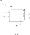
- Figure 1a shows a battery cell 110 comprising a bottom side U 111, two opposite side walls S 1 and S 2 112, two opposite side walls S 3 and S 4 113, the top side O 114 and two battery contacts 115 on the top side 114.
- Figure 1b shows another variant of a battery cell 110 comprising a bottom U 111, two opposite side walls S 1 and S 2 112, two opposite side walls S 3 and S 4 113, on each of which a battery contact 115 is present, and a top O 114.
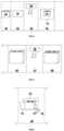
- the Figures 2-7 show various embodiments of a method for encasing a battery cell 110 according to Figure 1a In particular, the Figure 2 an embodiment of a method for encasing a battery cell 110.
- Step (i) 130 shows the provision of a battery cell 110, wherein the battery cell comprises at least two opposite side walls S 1 and S 2 , at least two opposite side walls S 3 and S 4 , at least one underside U and at least one top side O.
- Step (ii) 132 shows the provision of an adhesive film 116 with a width b 118 and a length l 117.
- Step (iii) 134 shows the bringing into contact of the adhesive film 116 and the at least one underside U of the battery cell 116, comprising gluing the at least one crosslinkable adhesive layer of the adhesive film 116 and the at least one underside U 111 of the battery cell, wherein the width b 118 of the adhesive film 116 protrudes by an area ⁇ b 1 119 beyond the underside U 111 of the battery cell 110.
- Step (iv) 136 shows the bringing into contact of the adhesive film 116 and the at least two side walls S 1 and S 2 112, comprising bonding the at least one crosslinkable adhesive layer of the adhesive film 116 and the at least two side walls S 1 and S 2 112, wherein the width b 118 of the adhesive film protrudes by area ⁇ b 2 121 beyond the at least two opposite side walls S 1 and S 2 112 of the battery cell 110 and wherein the length l 117 protrudes by area ⁇ l 1 120 beyond the top side O 114 of the battery cell 110.
- Steps (v) 138 and (vi) 140 show the bringing into contact of the adhesive film 116 and the at least two side walls S 3 and S 4 113, comprising bonding the at least one crosslinkable adhesive layer of the adhesive film 116 and the at least two side walls S 3 and S 4 113, wherein the width b 118 of the adhesive film 116 protrudes by area ⁇ b 3 122 beyond the underside of the battery cell 110, wherein ⁇ b 3 122 is bonded to the at least two side walls S 3 and S 4 113 and wherein ⁇ b 2 121 is bonded to the at least two side walls S 3 and S 4 113, comprising bonding the adhesive layer of the adhesive film 116 and the at least two side walls S 3 and S 4 113, to form area ⁇ l 2 124.
- Step (vi) 140 shows the bringing into contact of the adhesive film 116 and the at least one upper side O 114, comprising bonding the at least one crosslinkable adhesive layer of the adhesive film 116 and the at least one upper side O 114 of the battery cell 110, wherein ⁇ l 2 124 is bonded to the upper side O 114 of the battery cell 110 to form surface ⁇ l 3 125 and wherein ⁇ l 3 125 is bonded to the upper side O 114 of the battery cell 110, comprising bonding the adhesive layer of the adhesive film 116 and the at least one upper side O 114.
- the Figure 2 an embodiment of a coated battery cell 150 and an embodiment of a method for coating a battery cell 110, which further comprises at least one step of at least partially crosslinking the crosslinkable adhesive layer with a crosslinking unit 100.
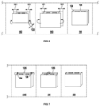
- the Figure 3 shows an embodiment of a method for encasing a battery cell 110, wherein the at least partial crosslinking of the crosslinkable adhesive layer after the step according to (ii) is carried out with a crosslinking unit 100 in step 133.
- the Figure 4 shows an embodiment of a method for encasing a battery cell 110, wherein the at least partial crosslinking of the crosslinkable adhesive layer after the step according to (vi) is carried out with a crosslinking unit 100 in step 141.
- the Figure 5 shows an enlarged section of step (iv) 136.
- the Figure 6 shows a preferred embodiment of steps (v) 138 and (vi) 140, wherein in step 142, first ⁇ b 3 122 is glued to the at least two side walls S 3 and S 4 113. Then in step 143, ⁇ b 2 121 is glued to the at least two side walls S 3 and S 4 113, forming surface ⁇ l 2 124.
- the Figure 7 shows a preferred embodiment of step 140, wherein the bringing into contact of the adhesive film 116 and the at least one upper side O 114, comprising bonding the at least one crosslinkable adhesive layer of the adhesive film 116 and the at least one upper side O 114 of the battery cell 110.
- ⁇ l 2 124 is first bonded to the upper side O 114 of the battery cell 110 to form surface ⁇ l 3 125. Then ⁇ l 3 125 is bonded to the upper side O 114 of the battery cell 110.
- the method for encasing a battery cell 110 proceeds analogously.
- the method begins with providing a battery cell 110, wherein the battery cell comprises at least two opposing side walls S 1 and S 2 , at least two opposing side walls S 3 and S 4 , at least one bottom U and at least one top side O. There is a battery contact on each of the two opposite side walls S 3 and S 4 .
- the adhesive film comprising at least one crosslinkable adhesive layer and at least one carrier, covers the two opposite side walls S 1 and S 2 , the bottom U and the top O in one piece, wherein the ends of the adhesive film are glued to one another in an overlapping manner.
- the adhesive film has a greater width than the opposite side walls S 1 and S 2 , the bottom U and the top O, so that the adhesive film has an overhang on the two opposite side walls S 3 and S 4 , which each have a battery contact.
- the individual sections which form the overhang on the side walls S 1 and S 2 , on the bottom U and on the top O are folded over and glued in any order onto the respective side wall S 3 and S 4 .
- the Figures 2-7 The method shown and described in the disclosure associated with the figures for encasing a battery cell 110 in which two battery contacts are present on the top side O can be transferred analogously to a battery cell 110 in which the side walls S 3 and S 4 each have a battery contact.
- the order of the sub-steps (v) and (vi) is swapped.
- Test method 1 specific volume resistance
- the volume resistivity was determined according to DIN EN 62631 -3-1 (VDE 0307-3-1): 2017-01.
- the adhesive strengths were determined analogously to ISO 29862 (method 3) at 23 °C and 50% relative humidity at a peel speed of 300 mm/min and a peel angle of 180°. Steel plates were used as the substrate in accordance with the standard. The measuring strip was bonded using a 4 kg rolling machine at a temperature of 23 °C. The adhesive films were peeled off immediately after application or after a storage time of 24 hours. The measured value (in N/cm) was the average of three individual measurements.
- the glass transition temperature of polymers is determined using dynamic scanning calorimetry (DSC). To do this, approximately 5 mg of the untreated polymer samples are weighed into an aluminum crucible (volume 25 ⁇ L) and closed with a perforated lid. A DSC 204 F1 from Netzsch is used for the measurement and the work is carried out under nitrogen for inerting. The sample is first cooled to -150 °C, heated to +150 °C at a heating rate of 10 K/min and cooled again to -150 °C. The subsequent second heating curve is run again at 10 K/min and the change in heat capacity is recorded. Glass transitions are recognized as steps in the thermogram. The glass transition temperature is evaluated as follows.
- a tangent is created on the base line of the thermogram before 1 and after 2 of the stage.
- a best-fit line 3 is placed parallel to the ordinate so that it intersects the two tangents in such a way that two surfaces 4 and 5 (between the one tangent, the best-fit line and the measurement curve) are created with the same content.
- the intersection of the best-positioned compensation line with the measurement curve gives the glass transition temperature.
- the dynamic viscosity is determined according to DIN 53019-1: from 2008-09; at 25 °C, with a shear rate of 1 s -1 .
- the softening temperature is determined according to the relevant methodology known as Ring and Ball and standardized according to ASTM E28 (1.7.2018).
- a ring-ball machine HRB 754 from Herzog is used to determine the softening temperature of the resins. Resin samples are first finely ground. The resulting powder is filled into a brass cylinder with a bottom opening (inner diameter at the top of the cylinder 20 mm, diameter of the bottom opening of the cylinder 16 mm, height of the cylinder 6 mm) and melted on a heating table. The filling quantity is selected so that the resin completely fills the cylinder after melting without any overhang.
- test specimen and cylinder are placed in the test holder of the HRB 754.
- Glycerin is used to fill the tempering bath, provided the softening temperature is between 50 °C and 150 °C.
- a water bath can also be used at lower softening temperatures become.
- the test balls have a diameter of 9.5 mm and weigh 3.5 g. According to the HRB 754 procedure, the ball is placed above the test specimen in the tempering bath and placed on the test specimen. There is a collecting plate 25 mm below the cylinder base and a light barrier 2 mm above it. During the measurement process, the temperature is increased at 5 °C/min.
- the ball In the temperature range of the softening temperature, the ball begins to move through the bottom opening of the cylinder until it finally comes to a stop on the collecting plate. In this position it is detected by the light barrier and the temperature of the temperature control bath is registered at this point. There is a double determination.
- the softening temperature is the average of the two individual measurements.
- Table 1 The raw materials used in the examples and comparative examples are summarized in Table 1.
- Table 1 Raw materials used Polyacrylate BA-GMA copolymer with a reactive content of 10 wt% GMA Levamelt 700 Ethylene-vinyl acetate copolymer from Arlanxeo with 70% vinyl acetate content Breon N45H80 Hot-polymerized nitrile rubber with 42% acrylonitrile content
- Araldite GY-250 Liquid bisphenol-A epoxy resin from Huntsman with an epoxy equivalent of 183 - 189 g/eq Araldite GT-6071 Solid bisphenol A epoxy resin from Huntsman with an epoxy equivalent of 450 - 465 g/eq Voranol 2070
- Polyether polyol with a molecular weight of M 700g/mol KH-560 3-Glycidoxypropyltrimethoxysilane Dyhard 100S Dicyandiamide from Alzchem with a particle size of less than 10 ⁇ m Curezol 2M
- Comparative examples V2-V3 were produced according to the weight ratios in% by weight in Table 2.
- Comparative example V1 is a commercially available, electrically insulating adhesive tape, tesa® 58353, consisting of 50 ⁇ m polyethylene terephthalate carrier with 35 ⁇ m acrylate adhesive layer.
- the adhesives dissolved in butanone were spread in a layer thickness of 35 ⁇ m onto a 50 ⁇ m polyethylene terephthalate carrier, freed from the solvent in a drying oven at 105 °C and covered with a siliconized PET liner.
- the bonding strength of the resulting adhesive layer was measured at a layer thickness of 100 ⁇ m and expressed in MPa.
- Examples K1 and K2 and comparative examples V2 and V3 were irradiated with 365 nm UV-LED radiation at 4 J/cm 2 and bonded within less than a minute after activation. The measurement was taken after a post-curing time of 7 days at 23 °C.
- Comparative example V1 is a non-reactive pressure-sensitive adhesive, so no activation is necessary.
- Example K3 is a thermally curable reactive pressure-sensitive adhesive that is cured for 25 minutes at 145 °C after application.
- the bond strength of a composite produced using the process according to the invention was determined for the different adhesive tapes as a parameter for the quality of the bond achieved.
- Rolls that press the adhesive tape onto the battery cell wall, starting from one side, are suitable for sticking the adhesive film on the battery cell walls without bubbles.
- the process example M2 was carried out like the process example M1, with the irradiation being carried out with the liner. It was irradiated with a dose of 4 J/cm 2 (UV-LED 365 nm, 4 s with 1000 mJ/cm 2 s) and then the liner was removed and the battery cell was encased as described in method example M1.
- Process example M3 was carried out like process example M1, with the difference that the adhesive film was only irradiated after the battery cell had been completely encased. In this case with a dose of greater than 5 J/cm 2 (UV-LED 365nm, 10s with 1000mJ/cm 2 s on each side) in order to reach the areas in which the adhesive film is multi-layered due to folding processes and over-gluing.
- the adhesive film was then exposed to thermal energy after covering the battery cell (20 minutes at 140 °C).
- Process Example M5 was carried out in the same way as Process Example M1, using K1 as the adhesive layer.
- steps 3) and 4) are in the reverse order.
- steps 3) and 4) and steps 5) and 6) are in reverse order.
- a battery cell wrapped in insulating tape was stored for 1000 hours in a climate chamber at 85 °C and 85% relative humidity (RH). The test was considered passed if after this time the edges of the bonding did not rise up at any of the bonds. Failure means that the insulating tape came loose in at least one place (often in the area of the folds) and thus separated from the cell.
- Comparative example V1 is a commercial pressure-sensitive adhesive, tesa® 58353, which does not have sufficient bonding strength to serve as a bonding base for other liquid adhesives.
- Examples V2 and V3 are characterized by high bond strengths after curing, but are too soft due to the lack of solid epoxy resins or too low a polymer content, so that the adhesive layer has too low cohesion, which is shown by cohesive failure in the uncured state in the adhesive strength test.
- Such soft adhesives are less suitable for the process claimed because, on the one hand, due to their low cohesion, they tend to come out of the wound adhesive tape rolls on the side and thus stick the rolls together and, on the other hand, when gluing around edges, the restoring force of the carrier film can cause them to stand up ( "edge lifting") or detachment of the film.
- edge lifting the restoring force of the carrier film can cause them to stand up ( "edge lifting") or detachment of the film.
- the fold connection on the small side walls S 3 and S 4 which was glued in step 4
- comparison method VM2 the edges of the small side walls of the top, which were glued in step 6), have come loose.
Landscapes
- Chemical & Material Sciences (AREA)
- Chemical Kinetics & Catalysis (AREA)
- General Chemical & Material Sciences (AREA)
- Electrochemistry (AREA)
- Organic Chemistry (AREA)
- Medicinal Chemistry (AREA)
- Polymers & Plastics (AREA)
- Health & Medical Sciences (AREA)
- Engineering & Computer Science (AREA)
- Aviation & Aerospace Engineering (AREA)
- Adhesives Or Adhesive Processes (AREA)
- Sealing Battery Cases Or Jackets (AREA)
- Connection Of Batteries Or Terminals (AREA)
- Adhesive Tapes (AREA)
- Laminated Bodies (AREA)
Applications Claiming Priority (1)
| Application Number | Priority Date | Filing Date | Title |
|---|---|---|---|
| DE102022124905.0A DE102022124905A1 (de) | 2022-09-28 | 2022-09-28 | Verfahren zur Ummantelung einer Batteriezelle |
Publications (2)
| Publication Number | Publication Date |
|---|---|
| EP4345992A2 true EP4345992A2 (fr) | 2024-04-03 |
| EP4345992A3 EP4345992A3 (fr) | 2024-10-16 |
Family
ID=87971855
Family Applications (1)
| Application Number | Title | Priority Date | Filing Date |
|---|---|---|---|
| EP23195495.9A Pending EP4345992A3 (fr) | 2022-09-28 | 2023-09-05 | Procédé de gainage d'un élément de batterie |
Country Status (6)
| Country | Link |
|---|---|
| US (1) | US20240106046A1 (fr) |
| EP (1) | EP4345992A3 (fr) |
| JP (1) | JP7693763B2 (fr) |
| KR (1) | KR20240044363A (fr) |
| CN (1) | CN117790865A (fr) |
| DE (1) | DE102022124905A1 (fr) |
Cited By (1)
| Publication number | Priority date | Publication date | Assignee | Title |
|---|---|---|---|---|
| WO2025261958A1 (fr) | 2024-06-17 | 2025-12-26 | Tesa Se | Procédé d'enveloppement d´éléments de batterie dans un film au moyen d'un dispositif d'enveloppement par film |
Citations (13)
| Publication number | Priority date | Publication date | Assignee | Title |
|---|---|---|---|---|
| US3018262A (en) | 1957-05-01 | 1962-01-23 | Shell Oil Co | Curing polyepoxides with certain metal salts of inorganic acids |
| US3117099A (en) | 1959-12-24 | 1964-01-07 | Union Carbide Corp | Curable mixtures comprising epoxide compositions and divalent tin salts |
| US3729313A (en) | 1971-12-06 | 1973-04-24 | Minnesota Mining & Mfg | Novel photosensitive systems comprising diaryliodonium compounds and their use |
| US3741769A (en) | 1972-10-24 | 1973-06-26 | Minnesota Mining & Mfg | Novel photosensitive polymerizable systems and their use |
| US4058401A (en) | 1974-05-02 | 1977-11-15 | General Electric Company | Photocurable compositions containing group via aromatic onium salts |
| US4138255A (en) | 1977-06-27 | 1979-02-06 | General Electric Company | Photo-curing method for epoxy resin using group VIa onium salt |
| US4231951A (en) | 1978-02-08 | 1980-11-04 | Minnesota Mining And Manufacturing Company | Complex salt photoinitiator |
| US4250053A (en) | 1979-05-21 | 1981-02-10 | Minnesota Mining And Manufacturing Company | Sensitized aromatic iodonium or aromatic sulfonium salt photoinitiator systems |
| US4256828A (en) | 1975-09-02 | 1981-03-17 | Minnesota Mining And Manufacturing Company | Photocopolymerizable compositions based on epoxy and hydroxyl-containing organic materials |
| US4394403A (en) | 1974-05-08 | 1983-07-19 | Minnesota Mining And Manufacturing Company | Photopolymerizable compositions |
| EP0542716B1 (fr) | 1982-11-22 | 1997-06-25 | Minnesota Mining And Manufacturing Company | Compositions polymérisables par apport d'énergie contenant des initiateurs organométalliques |
| US6908722B2 (en) | 2001-06-29 | 2005-06-21 | Jsr Corporation | Acid generator, sulfonic acid, sulfonic acid derivatives and radiation-sensitive resin composition |
| US20100063221A1 (en) | 2006-12-01 | 2010-03-11 | Kaneka Corporation | Polysiloxane composition |
Family Cites Families (10)
| Publication number | Priority date | Publication date | Assignee | Title |
|---|---|---|---|---|
| JP2002184364A (ja) * | 2000-12-19 | 2002-06-28 | Matsushita Electric Ind Co Ltd | 角型電池およびその外装方法 |
| JP2004087277A (ja) * | 2002-08-27 | 2004-03-18 | Sanyo Gs Soft Energy Co Ltd | 電池パック |
| DE102010041143A1 (de) * | 2010-09-21 | 2012-03-22 | Sb Limotive Company Ltd. | Gehäuse für galvanisches Element |
| DE102015211656A1 (de) * | 2014-12-10 | 2016-06-16 | Robert Bosch Gmbh | Batteriezelle mit elektrisch isolierender Folie mit Konturierung |
| JP2016162734A (ja) * | 2015-03-05 | 2016-09-05 | 日東電工株式会社 | 被覆材付非水系二次電池、その製造方法および電池スタック |
| WO2017174303A1 (fr) * | 2016-04-04 | 2017-10-12 | Tesa Se | Ruban autoadhésif activable par un rayonnement présentant une réaction indépendante de la lumière et son utilisation |
| JP6967339B2 (ja) * | 2016-09-06 | 2021-11-17 | 日東電工株式会社 | 電池外装用粘着テープ |
| DE102017001696A1 (de) * | 2017-02-22 | 2018-08-23 | Lohmann Gmbh & Co. Kg | UV-aktivierbares strukturelles Haftklebeband |
| JP7580400B2 (ja) * | 2019-05-28 | 2024-11-11 | スリーエム イノベイティブ プロパティズ カンパニー | 硬化性感圧接着剤組成物、硬化性感圧接着テープ、及びバッテリーパック |
| CN111628120A (zh) * | 2020-06-18 | 2020-09-04 | 苏州凌威新能源科技有限公司 | 锂电池包装膜及其制备方法 |
-
2022
- 2022-09-28 DE DE102022124905.0A patent/DE102022124905A1/de active Pending
-
2023
- 2023-09-05 EP EP23195495.9A patent/EP4345992A3/fr active Pending
- 2023-09-13 JP JP2023148043A patent/JP7693763B2/ja active Active
- 2023-09-22 US US18/371,849 patent/US20240106046A1/en active Pending
- 2023-09-26 KR KR1020230129066A patent/KR20240044363A/ko active Pending
- 2023-09-26 CN CN202311248783.0A patent/CN117790865A/zh active Pending
Patent Citations (13)
| Publication number | Priority date | Publication date | Assignee | Title |
|---|---|---|---|---|
| US3018262A (en) | 1957-05-01 | 1962-01-23 | Shell Oil Co | Curing polyepoxides with certain metal salts of inorganic acids |
| US3117099A (en) | 1959-12-24 | 1964-01-07 | Union Carbide Corp | Curable mixtures comprising epoxide compositions and divalent tin salts |
| US3729313A (en) | 1971-12-06 | 1973-04-24 | Minnesota Mining & Mfg | Novel photosensitive systems comprising diaryliodonium compounds and their use |
| US3741769A (en) | 1972-10-24 | 1973-06-26 | Minnesota Mining & Mfg | Novel photosensitive polymerizable systems and their use |
| US4058401A (en) | 1974-05-02 | 1977-11-15 | General Electric Company | Photocurable compositions containing group via aromatic onium salts |
| US4394403A (en) | 1974-05-08 | 1983-07-19 | Minnesota Mining And Manufacturing Company | Photopolymerizable compositions |
| US4256828A (en) | 1975-09-02 | 1981-03-17 | Minnesota Mining And Manufacturing Company | Photocopolymerizable compositions based on epoxy and hydroxyl-containing organic materials |
| US4138255A (en) | 1977-06-27 | 1979-02-06 | General Electric Company | Photo-curing method for epoxy resin using group VIa onium salt |
| US4231951A (en) | 1978-02-08 | 1980-11-04 | Minnesota Mining And Manufacturing Company | Complex salt photoinitiator |
| US4250053A (en) | 1979-05-21 | 1981-02-10 | Minnesota Mining And Manufacturing Company | Sensitized aromatic iodonium or aromatic sulfonium salt photoinitiator systems |
| EP0542716B1 (fr) | 1982-11-22 | 1997-06-25 | Minnesota Mining And Manufacturing Company | Compositions polymérisables par apport d'énergie contenant des initiateurs organométalliques |
| US6908722B2 (en) | 2001-06-29 | 2005-06-21 | Jsr Corporation | Acid generator, sulfonic acid, sulfonic acid derivatives and radiation-sensitive resin composition |
| US20100063221A1 (en) | 2006-12-01 | 2010-03-11 | Kaneka Corporation | Polysiloxane composition |
Non-Patent Citations (1)
| Title |
|---|
| VON A.W. GREEN, INDUSTRIAL PHOTOINITIATORS: A TECHNICAL GUIDE, 2010 |
Cited By (1)
| Publication number | Priority date | Publication date | Assignee | Title |
|---|---|---|---|---|
| WO2025261958A1 (fr) | 2024-06-17 | 2025-12-26 | Tesa Se | Procédé d'enveloppement d´éléments de batterie dans un film au moyen d'un dispositif d'enveloppement par film |
Also Published As
| Publication number | Publication date |
|---|---|
| CN117790865A (zh) | 2024-03-29 |
| JP7693763B2 (ja) | 2025-06-17 |
| US20240106046A1 (en) | 2024-03-28 |
| DE102022124905A1 (de) | 2024-03-28 |
| EP4345992A3 (fr) | 2024-10-16 |
| KR20240044363A (ko) | 2024-04-04 |
| JP2024049348A (ja) | 2024-04-09 |
Similar Documents
| Publication | Publication Date | Title |
|---|---|---|
| EP3091059B1 (fr) | Bande collante et masse collante a phase polymere continue | |
| EP3440143B1 (fr) | Ruban autoadhésif activable par un rayonnement présentant une réaction indépendante de la lumière et son utilisation | |
| EP3452540B1 (fr) | Composition adhesive curable et bandes adhésifs réactives correspondantes | |
| DE102015217860A1 (de) | Klebeband mit Klebemasse mit kontinuierlicher Polymerphase | |
| EP3452524B1 (fr) | Masse adhésive faisant barrière à la vapeur d'eau, comprenant du poly(méth)acrylate hautement fonctionnalisé | |
| EP2951123B1 (fr) | Masse adhésive comprenant un réseau de nanoparticules reliées, son procédé de fabrication ainsi que son utilisation | |
| EP3212725B1 (fr) | Matières adhésives oled-compatibles comportant des agents de captation d'eau silanée | |
| EP3137566B1 (fr) | Procédé pour réaliser un collage sur des surfaces sensibles aux perméats | |
| EP4242277B1 (fr) | Matière adhésive durcissable ayant une aptitude au poinçonnage améliorée et des propriétés de choc améliorées | |
| DE102014208109A1 (de) | Spaltbares Klebend mit dosierfähigen spaltbaren Flüssigklebstoff | |
| DE102021206799A1 (de) | Stanzbares Reaktivklebeband | |
| DE102022105738A1 (de) | Aushärtbare Klebemasse mit verbesserter Stanzbarkeit | |
| DE102022124905A1 (de) | Verfahren zur Ummantelung einer Batteriezelle | |
| EP3885418A1 (fr) | Film adhésif latent réactif | |
| WO1999033897A1 (fr) | Adhesifs pour stratifies durcissables par rayonnement | |
| WO2020069884A1 (fr) | Film adhésif à réactivité latente | |
| EP4345144B1 (fr) | Matière adhésive durcissable à propriétés adhésives améliorées | |
| EP3101079A1 (fr) | Masse collante formant barriere a la vapeur d'eau comprenant un sirop epoxyde pre-polymerise | |
| WO2019162035A1 (fr) | Composition pour produire une masse adhésive, en particulier pour encapsuler un dispositif électronique | |
| DE102022124902A1 (de) | Kationisch härtbare Klebemasse mit Indikation der Haltefestigkeit | |
| DE60223308T2 (de) | Kationisch polymerisierbare Flüssigkeitszusammensetzung und Klebstoffpolymer | |
| DE102024107753A1 (de) | Reaktives Klebeband | |
| DE102022124903A1 (de) | Kationisch härtbare Klebemasse mit definierter Färbung im ausgehärteten Zustand | |
| DE102023135599A1 (de) | Aushärtbare Haftklebemasse mit hoher Verklebungsfestigkeit und guter Klebkraft im ausgehärteten Zustand | |
| DE102024107751A1 (de) | Chemikalienbeständige, reaktiv aushärtbare Klebemasse und Klebeband |
Legal Events
| Date | Code | Title | Description |
|---|---|---|---|
| PUAI | Public reference made under article 153(3) epc to a published international application that has entered the european phase |
Free format text: ORIGINAL CODE: 0009012 |
|
| STAA | Information on the status of an ep patent application or granted ep patent |
Free format text: STATUS: THE APPLICATION HAS BEEN PUBLISHED |
|
| REG | Reference to a national code |
Ref country code: DE Ref legal event code: R079 Free format text: PREVIOUS MAIN CLASS: H01M0050121000 Ipc: H01M0050103000 |
|
| AK | Designated contracting states |
Kind code of ref document: A2 Designated state(s): AL AT BE BG CH CY CZ DE DK EE ES FI FR GB GR HR HU IE IS IT LI LT LU LV MC ME MK MT NL NO PL PT RO RS SE SI SK SM TR |
|
| RIC1 | Information provided on ipc code assigned before grant |
Ipc: H01M 50/231 20210101ALI20240318BHEP Ipc: H01M 50/227 20210101ALI20240318BHEP Ipc: H01M 50/202 20210101ALI20240318BHEP Ipc: H01M 50/103 20210101AFI20240318BHEP |
|
| PUAL | Search report despatched |
Free format text: ORIGINAL CODE: 0009013 |
|
| AK | Designated contracting states |
Kind code of ref document: A3 Designated state(s): AL AT BE BG CH CY CZ DE DK EE ES FI FR GB GR HR HU IE IS IT LI LT LU LV MC ME MK MT NL NO PL PT RO RS SE SI SK SM TR |
|
| RIC1 | Information provided on ipc code assigned before grant |
Ipc: C09J 163/00 20060101ALI20240909BHEP Ipc: C08L 63/00 20060101ALI20240909BHEP Ipc: H01M 50/231 20210101ALI20240909BHEP Ipc: H01M 50/227 20210101ALI20240909BHEP Ipc: H01M 50/202 20210101ALI20240909BHEP Ipc: H01M 50/103 20210101AFI20240909BHEP |
|
| STAA | Information on the status of an ep patent application or granted ep patent |
Free format text: STATUS: REQUEST FOR EXAMINATION WAS MADE |
|
| 17P | Request for examination filed |
Effective date: 20250416 |
|
| STAA | Information on the status of an ep patent application or granted ep patent |
Free format text: STATUS: EXAMINATION IS IN PROGRESS |
|
| 17Q | First examination report despatched |
Effective date: 20250929 |