EP4346029A2 - Dispositif d'assurance de position de connecteur, appareil connecteur ayant des ensembles connecteurs mâle et femelle avec dispositif d'assurance de position de connecteur, ensemble connecteur mâle, ensemble connecteur femelle et procédé d'assemblage de l'appareil connecteur - Google Patents
Dispositif d'assurance de position de connecteur, appareil connecteur ayant des ensembles connecteurs mâle et femelle avec dispositif d'assurance de position de connecteur, ensemble connecteur mâle, ensemble connecteur femelle et procédé d'assemblage de l'appareil connecteur Download PDFInfo
- Publication number
- EP4346029A2 EP4346029A2 EP24158553.8A EP24158553A EP4346029A2 EP 4346029 A2 EP4346029 A2 EP 4346029A2 EP 24158553 A EP24158553 A EP 24158553A EP 4346029 A2 EP4346029 A2 EP 4346029A2
- Authority
- EP
- European Patent Office
- Prior art keywords
- connector assembly
- female connector
- male
- female
- connector
- Prior art date
- Legal status (The legal status is an assumption and is not a legal conclusion. Google has not performed a legal analysis and makes no representation as to the accuracy of the status listed.)
- Pending
Links
Images




Classifications
-
- H—ELECTRICITY
- H01—ELECTRIC ELEMENTS
- H01R—ELECTRICALLY-CONDUCTIVE CONNECTIONS; STRUCTURAL ASSOCIATIONS OF A PLURALITY OF MUTUALLY-INSULATED ELECTRICAL CONNECTING ELEMENTS; COUPLING DEVICES; CURRENT COLLECTORS
- H01R13/00—Details of coupling devices of the kinds covered by groups H01R12/70 or H01R24/00 - H01R33/00
- H01R13/62—Means for facilitating engagement or disengagement of coupling parts or for holding them in engagement
- H01R13/627—Snap or like fastening
- H01R13/6275—Latching arms not integral with the housing
-
- H—ELECTRICITY
- H01—ELECTRIC ELEMENTS
- H01R—ELECTRICALLY-CONDUCTIVE CONNECTIONS; STRUCTURAL ASSOCIATIONS OF A PLURALITY OF MUTUALLY-INSULATED ELECTRICAL CONNECTING ELEMENTS; COUPLING DEVICES; CURRENT COLLECTORS
- H01R13/00—Details of coupling devices of the kinds covered by groups H01R12/70 or H01R24/00 - H01R33/00
- H01R13/62—Means for facilitating engagement or disengagement of coupling parts or for holding them in engagement
- H01R13/627—Snap or like fastening
- H01R13/6271—Latching means integral with the housing
- H01R13/6272—Latching means integral with the housing comprising a single latching arm
-
- H—ELECTRICITY
- H01—ELECTRIC ELEMENTS
- H01R—ELECTRICALLY-CONDUCTIVE CONNECTIONS; STRUCTURAL ASSOCIATIONS OF A PLURALITY OF MUTUALLY-INSULATED ELECTRICAL CONNECTING ELEMENTS; COUPLING DEVICES; CURRENT COLLECTORS
- H01R13/00—Details of coupling devices of the kinds covered by groups H01R12/70 or H01R24/00 - H01R33/00
- H01R13/40—Securing contact members in or to a base or case; Insulating of contact members
- H01R13/42—Securing in a demountable manner
- H01R13/436—Securing a plurality of contact members by one locking piece or operation
- H01R13/4361—Insertion of locking piece perpendicular to direction of contact insertion
- H01R13/4362—Insertion of locking piece perpendicular to direction of contact insertion comprising a temporary and a final locking position
-
- H—ELECTRICITY
- H01—ELECTRIC ELEMENTS
- H01R—ELECTRICALLY-CONDUCTIVE CONNECTIONS; STRUCTURAL ASSOCIATIONS OF A PLURALITY OF MUTUALLY-INSULATED ELECTRICAL CONNECTING ELEMENTS; COUPLING DEVICES; CURRENT COLLECTORS
- H01R13/00—Details of coupling devices of the kinds covered by groups H01R12/70 or H01R24/00 - H01R33/00
- H01R13/46—Bases; Cases
- H01R13/502—Bases; Cases composed of different pieces
- H01R13/506—Bases; Cases composed of different pieces assembled by snap action of the parts
-
- H—ELECTRICITY
- H01—ELECTRIC ELEMENTS
- H01R—ELECTRICALLY-CONDUCTIVE CONNECTIONS; STRUCTURAL ASSOCIATIONS OF A PLURALITY OF MUTUALLY-INSULATED ELECTRICAL CONNECTING ELEMENTS; COUPLING DEVICES; CURRENT COLLECTORS
- H01R43/00—Apparatus or processes specially adapted for manufacturing, assembling, maintaining, or repairing of line connectors or current collectors or for joining electric conductors
- H01R43/26—Apparatus or processes specially adapted for manufacturing, assembling, maintaining, or repairing of line connectors or current collectors or for joining electric conductors for engaging or disengaging the two parts of a coupling device
-
- H—ELECTRICITY
- H01—ELECTRIC ELEMENTS
- H01R—ELECTRICALLY-CONDUCTIVE CONNECTIONS; STRUCTURAL ASSOCIATIONS OF A PLURALITY OF MUTUALLY-INSULATED ELECTRICAL CONNECTING ELEMENTS; COUPLING DEVICES; CURRENT COLLECTORS
- H01R13/00—Details of coupling devices of the kinds covered by groups H01R12/70 or H01R24/00 - H01R33/00
- H01R13/62—Means for facilitating engagement or disengagement of coupling parts or for holding them in engagement
- H01R13/639—Additional means for holding or locking coupling parts together, after engagement, e.g. separate keylock, retainer strap
Definitions
- the present invention generally relates to a connector position assurance (CPA) device for assuring the engagement of male and female connector assemblies, a connector apparatus having the male connector assembly and the female connector assembly, the male connector assembly having a male terminal position assurance (TPA) device for connecting thereto at least a set of terminals, and the female connector assembly having a female terminal position (TPA) device for connecting thereto at least a set of terminals.
- the female connector assembly further includes the CPA device for locking the male and female connector assemblies together.
- a connector position assurance (CPA) device for assuring the engagement of male and female connector assemblies is inserted into the female connector assembly, at a pre-lock position and then, at a full-lock position. Further, to ensure that the female terminal position assurance (TPA) device is made available for connecting to the female connector assembly during transport thereof, the female TPA is engaged, in a pre-lock position, to the female connector assembly.
- a male terminal position assurance (TPA) device may be made available for connecting to the male connector assembly during transport thereof, the male TPA being able to be engaged, in a pre-lock position, to the male connector assembly.
- the female connector assembly engages thereto, during the transport thereof, with the connector position assurance (CPA) device at a pre-lock position.
- At least a terminal is provided into each of the male connector assembly and the female connector assembly, when each of their respective male TPA and female TPA is at a pre-lock position.
- the male connector assembly and female connector assembly are engaged together, and the engagement thereof is assured when the CPA device is placed at a full-lock position.
- the set of terminals provided for the male connector assembly is secured thereto when the male TPA thereof is placed at a full-lock position.
- the set of terminals provided for the female connector assembly is secured thereto when the female TPA device thereof is placed at a full-lock position.
- the female connector assembly can enter the inside of the male connector assembly, and both the male and female connector assemblies can be fully engaged together with the CPA device and the full engagement thereof is assured when the CPA device is at a full-lock position.
- FIG. 1 illustrates, in an exploded perspective view, the connector apparatus, generally referred to by reference number 1, which includes a female connector assembly 3 and a male connector assembly 5.
- the female connector assembly 3 includes a female terminal position assurance (TPA) device 6 and a connector position assurance (CPA) device 8.
- TPA female terminal position assurance
- CPA connector position assurance
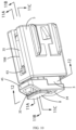
- FIGS. 2A, 2B, and 2C show the female connector assembly having an upper side 18, a lower side 20, a first side 22, a second side 24, a front end side 26, and a back end side 28.
- FIGS. 2A and 2B illustrate the female connector assembly 3, which includes a side slot 13 on the first side 22 thereof and a top slot 15 on the upper side 18 thereof.
- the side slot 13 receives the female terminal assurance (TPA) device 6.
- TPA female terminal assurance
- elongated member 30 Between the side slot 13 and the top slot 15 is an elongated member 30. Passing through a portion of the back end side 28 is a set of terminal slots 33.
- FIG. 2B Further illustrated in FIG. 2B is a flexible member 35 extending along the second side 24 of the female connector assembly 3, a front end 40 of the flexible member 35 extending near an opening 42 of the front end side 26 of the female connector assembly 3. At an intermediate portion of the flexible member 35 are protruding members 43 extending therefrom. Also passing through the front end side 26 is another set of terminal slots 34. Bounded at an upper portion of the opening 42 is a substantially U-shaped member 45.
- the female connector assembly 3 includes a substantially ramp-like member 46 with a substantially flat portion 50 at an upper portion thereof continuing with an elongated guide member 52.
- first window 55 and second window 57 passing through the lower side 20 of the female connector assembly 3 are a first window 55 and a second window 57. Therebetween the first and second windows 55, 57 is a bridge member 60.
- FIGS. 3A, 3B, and 3C are perspective views of the CPA device 8 for locking the female connector assembly 3 and the male connector assembly 5 together, at a pre-lock position or at a full-lock position.
- Shown in FIG. 3A are a flexible side member 70 with a side end portion 72 and a set of side ledges 75.
- the CPA device 8 further includes a flexible bottom side member 77 with a wedge-like member 80 at an end thereof. Adjacent the base of the wedge-like member 80 is a front ledge 81 and a back ledge 83.
- the CPA device 8 has an end portion 85.
- the CPA device 8 further including an inner flexible member 88 attached to an end 90 thereof to the flexible bottom side member 77.
- the inner flexible member 88 provides a spring-like action or an essential resilience property for the flexible bottom side member 77, as will later be discussed.
- an opening 92 is shown in FIGS. 3A and 3B, preferably elongated, the opening 92 passing through an inner portion of the flexible side member 70.
- the back ledge 83 near the wedge-like member 80 and the wedge-like member 80 form a substantially U-shaped portion on the bottom side member 77, the significance of which will later be discussed.
- the flexible bottom side member 77 is flexible towards the flexible side member 70.
- FIG. 4 illustrates the TPA device 6 of the female connector assembly 3.
- the TPA device 6 is substantially L-shaped, although the general shape thereof is not limited thereto. Extending from a top portion 98 of the female TPA device 6 are a pair of elongated members 100, 102.
- FIG. 5A Generally shown in FIG. 5A is the male connector assembly 5, shown in a generic form, having a one end portion 105 and another end portion 107.
- the male connector assembly 5 includes a second side elongated slot 108.
- An opening 110, for accommodating therein the female connector assembly 3, has an opening portion 112 with a wider width.
- FIG. 5B illustrates an internal space 103 for accommodating therein the female connector assembly 3, and further illustrates a set of terminal apertures 106 at the end portion 107 of the male connector assembly 5.
- the opening portion 112 includes substantially U-shaped side portions 115 for guiding the entry of the female connector assembly 3 through the opening 110 of the male connector assembly 5.
- the internal space 103 may accommodate therein a male terminal position assurance (TPA) device for securing therein a set of terminals passing through the set of terminal apertures 105.
- TPA terminal position assurance
- the TPA device 6 of the female connector assembly 3 is inserted into the side slot 13 of the female connector assembly 3 such that the elongated member 100 passes beneath the elongated member 30 and becomes positioned within the top slot 15 of the female connector assembly 3, the TPA device 6 being in a pre-lock position.
- the CPA device 8 is in a pre-lock position with the female connector assembly 3, while the TPA device 6 is similarly in a pre-lock position. With the TPA device and the CPA device 8 in pre-lock positions, the female connector assembly 3 is ready for transport.
- the TPA device 6 When a set of terminals (not shown) is inserted through the set of terminal slots 33 of the female connector assembly 3, the TPA device 6 is further pushed inward through the side slot 13 with the elongated member 102 of the TPA device 6 being pushed past the elongated member 30 of the female connector assembly 3 and passes into the top slot 15 of the female connector assembly 3. The TPA device 6 is then at a final-lock position, as shown in FIG. 6C .
- the TPA device 6 is at a pre-lock position when, as shown in FIG. 7A , the elongated member 100 of the TPA device 6, while the TPA device 6 is being pushed through the side slot 13, passes the elongated member 30 of the female connector assembly 3 and into the top slot 15 of the female connector assembly 3.
- the elongated member 102 of the TPA device 6 passes the elongated member 30 of the female connector assembly 3 and into the top slot 15.
- the TPA device 6 is fully inserted into the female connector assembly 3 so that no part of the TPA device 6 extends beyond pass the first side 22 of the female connector assembly 3.
- the TPA device 6 When the TPA device 6 is in a full-lock position within the female connector assembly 3, the TPA device 6 has secured the set of terminals (not shown) intended to be joined with the female connector assembly 3, and the female connector assembly 3 is ready to be inserted into the male connector assembly 5 for coupling thereto. That is, no part of the TPA device 6 extends beyond the first side 22 of the female connector assembly 3 to permit the female connector assembly 3 to fully enter, unimpeded, through the openings 110, 112 (see FIG. 5B ) and into the male connector assembly 5.
- the CPA device 8 (at a pre-lock position inside the female connector assembly 3) can be further inserted into the female connector assembly 3 at a full-lock position therein to ensure that the female and male connector assemblies 3, 5 become fully engaged.
- FIGS. 8 , 9A, 9B, and 9C illustrate the female connector assembly 3 and the male connector assembly 5 being engaged, while the CPA device 8 is at a pre-lock position.
- the protruding members 43 extending from the flexible member 35 (as discussed above in describing FIG. 2B ) of the female connector assembly 3 has entered the second side elongated slot 108 (see, also, FIG. 5A ) of the male connector assembly 5.
- the CPA device 8 at a pre-lock position has its wedge-like member 80 of its flexible bottom side member 77 (see, also, FIG. 3A ) enter the first window 55 (as discussed above in describing FIG.
- the front face of the wedge-like member 80 is preferably in an inclined shape, and the inner flexible member 88 (attached at an end 90 thereof to the flexible bottom side member 77 of the CPA device) provides the spring-like action or the essential resilience property of the flexible bottom side member 77 (see, also, FIG. 3B ).
- the side end portion 72 of the flexible side member 70 (see, also, FIGS. 3A, 3B, and 3C ) of the CPA device 8 has traversed the elongated guide member 52 and the ramp-like member 46 (see, also, FIG. 2B ) of the female connector assembly 3 and the side end portion 72 rests upon the substantially flat portion 50 of the ramp-like member 46.
- a sound also preferably a clicking sound or the like
- the wedge-like member 80 of the CPA device 8 (fitted inside the first window 55 of the female connector assembly 3) prevents the CPA device 8 from traversing further forward, while the side end portion 72 of the CPA device 8 mounted onto the substantially flat portion 50 of the ramp-like member 46 of the female connector assembly 3 prevents the CPA device 8 from traversing backwards.
- the female connector assembly 3 is ready to be transported to a location where both the female connector assembly 3 can be engaged with the male connector assembly 5 (preferably with its male TPA device (not shown) at a pre-lock position inside the male connector assembly 5 when being transported or the male TPA device (not shown) at a full-lock position when engaging therein the set of terminals (also not shown) and then inserted into the female connector assembly 3 for engagement thereto).
- the male connector assembly 5 preferably with its male TPA device (not shown) at a pre-lock position inside the male connector assembly 5 when being transported or the male TPA device (not shown) at a full-lock position when engaging therein the set of terminals (also not shown) and then inserted into the female connector assembly 3 for engagement thereto).
- the protruding members 43 of the flexible member 35 of the female connector assembly 5 enter the second side elongated slot 108 of the male connector assembly 5.
- the flexible member 35 may still be pushed so that the protruding members 43 may be similarly pushed to clear the side of the male connector assembly 5 and thereafter, if desired, the female connector assembly 4 may be still be pulled away from the male connector assembly 5.
- the CPA device 8 is at a full-lock position, as shown in FIGS. 10 , 11A, 11B, 11C , and 12 , the set of side ledges 75 (see, FIG.
- the CPA device 8 is at a full-lock position with the female connector assembly 3 when the CPA device 8 (at a pre-lock position) is further pushed into the female connector assembly 3.
- the wedge-like member 80 of the CPA device 8 traverses the bridge member 60 (between the first and second windows 55, 57) and into the second window 57 of the female connector assembly 3 (see, FIGS. 11B and 11C ).
- a sound preferably a clicking sound or the like
- the wedge-like member 80 enters the second window 57 as shown in FIGS.
- the side end portion 72 of the flexible side member 70 of the CPA device 8 traverses the substantially flat portion 50 of the ramp-like member 46 of the female connector assembly 3, and the substantially flat portion 50 enters the opening 92 that passes through the inner portion of the flexible side member 70 (see, also, FIGS. 3A and 3B ) of the CPA device 8.
- a sound also preferably a clicking sound or the like
- the CPA device 8 is at a full-lock position.
- the CPA device 8 when the CPA device 8 is at a full-lock position, the set of side ledges 75 of the CPA device 8 are positioned beneath the flexible member 35, as shown in FIG. 12 , and thus, the flexible member 35 cannot be pushed and consequently, the protruding members 43 of the flexible member 35 cannot clear the side within the second side elongated slot 108 of the male connector assembly 5.
- the female connector assembly 3 cannot be pulled away from the male connector assembly 5, and thereby ensuring that the female and male connector assemblies 3, 5, when engaged, remain fully locked together.
Landscapes
- Engineering & Computer Science (AREA)
- Manufacturing & Machinery (AREA)
- Details Of Connecting Devices For Male And Female Coupling (AREA)
Applications Claiming Priority (4)
| Application Number | Priority Date | Filing Date | Title |
|---|---|---|---|
| US201762492414P | 2017-05-01 | 2017-05-01 | |
| US15/957,257 US10454209B2 (en) | 2017-05-01 | 2018-04-19 | Connector position assurance device, a connector apparatus having male and female connector assemblies with connector position assurance device, a male connector assembly, a female connector assembly, and a method for assembling the connector apparatus |
| PCT/US2018/029822 WO2018204188A1 (fr) | 2017-05-01 | 2018-04-27 | Dispositif d'assurance de position de connecteur, appareil connecteur ayant des ensembles connecteurs mâle et femelle avec dispositif d'assurance de position de connecteur, ensemble connecteur mâle, ensemble connecteur femelle et procédé d'assemblage de l'appareil connecteur |
| EP18794537.3A EP3619777B1 (fr) | 2017-05-01 | 2018-04-27 | Dispositif d'assurance de position de connecteur, appareil connecteur ayant des ensembles connecteurs mâle et femelle avec dispositif d'assurance de position de connecteur, ensemble connecteur mâle, ensemble connecteur femelle et procédé d'assemblage de l'appareil connecteur |
Related Parent Applications (2)
| Application Number | Title | Priority Date | Filing Date |
|---|---|---|---|
| EP18794537.3A Division EP3619777B1 (fr) | 2017-05-01 | 2018-04-27 | Dispositif d'assurance de position de connecteur, appareil connecteur ayant des ensembles connecteurs mâle et femelle avec dispositif d'assurance de position de connecteur, ensemble connecteur mâle, ensemble connecteur femelle et procédé d'assemblage de l'appareil connecteur |
| EP18794537.3A Division-Into EP3619777B1 (fr) | 2017-05-01 | 2018-04-27 | Dispositif d'assurance de position de connecteur, appareil connecteur ayant des ensembles connecteurs mâle et femelle avec dispositif d'assurance de position de connecteur, ensemble connecteur mâle, ensemble connecteur femelle et procédé d'assemblage de l'appareil connecteur |
Publications (2)
| Publication Number | Publication Date |
|---|---|
| EP4346029A2 true EP4346029A2 (fr) | 2024-04-03 |
| EP4346029A3 EP4346029A3 (fr) | 2024-06-19 |
Family
ID=63916899
Family Applications (4)
| Application Number | Title | Priority Date | Filing Date |
|---|---|---|---|
| EP24158553.8A Pending EP4346029A3 (fr) | 2017-05-01 | 2018-04-27 | Connecteur mâle, ensemble connecteur femelle et procédé d'assemblage de l'appareil connecteur |
| EP24158547.0A Pending EP4346028A3 (fr) | 2017-05-01 | 2018-04-27 | Connecteur mâle, ensemble connecteur femelle et procédé d'assemblage de l'appareil connecteur |
| EP18794537.3A Active EP3619777B1 (fr) | 2017-05-01 | 2018-04-27 | Dispositif d'assurance de position de connecteur, appareil connecteur ayant des ensembles connecteurs mâle et femelle avec dispositif d'assurance de position de connecteur, ensemble connecteur mâle, ensemble connecteur femelle et procédé d'assemblage de l'appareil connecteur |
| EP24158530.6A Pending EP4346027A3 (fr) | 2017-05-01 | 2018-04-27 | Connecteur mâle, ensemble connecteur femelle et procédé d'assemblage de l'appareil connecteur |
Family Applications After (3)
| Application Number | Title | Priority Date | Filing Date |
|---|---|---|---|
| EP24158547.0A Pending EP4346028A3 (fr) | 2017-05-01 | 2018-04-27 | Connecteur mâle, ensemble connecteur femelle et procédé d'assemblage de l'appareil connecteur |
| EP18794537.3A Active EP3619777B1 (fr) | 2017-05-01 | 2018-04-27 | Dispositif d'assurance de position de connecteur, appareil connecteur ayant des ensembles connecteurs mâle et femelle avec dispositif d'assurance de position de connecteur, ensemble connecteur mâle, ensemble connecteur femelle et procédé d'assemblage de l'appareil connecteur |
| EP24158530.6A Pending EP4346027A3 (fr) | 2017-05-01 | 2018-04-27 | Connecteur mâle, ensemble connecteur femelle et procédé d'assemblage de l'appareil connecteur |
Country Status (5)
| Country | Link |
|---|---|
| US (1) | US10454209B2 (fr) |
| EP (4) | EP4346029A3 (fr) |
| JP (1) | JP7086046B2 (fr) |
| CN (1) | CN110612643B (fr) |
| WO (1) | WO2018204188A1 (fr) |
Families Citing this family (17)
| Publication number | Priority date | Publication date | Assignee | Title |
|---|---|---|---|---|
| FR3088491B1 (fr) * | 2018-11-12 | 2021-12-03 | Raydiall | Boitier de connecteur equipe d'un dispositif d'assurance de position de terminal de cable (tpa) ameliore |
| CN109361112B (zh) * | 2018-11-16 | 2024-04-05 | 上海慷梭汽车电子科技有限公司 | 一种连接器 |
| US10892579B2 (en) | 2019-02-25 | 2021-01-12 | J.S.T. Corporation | Female terminal position assurance (TPA) device for a connector and method for assembling thereof |
| JP1649408S (fr) | 2019-06-21 | 2020-01-14 | ||
| JP1649407S (fr) | 2019-06-21 | 2020-01-14 | ||
| JP1649406S (fr) * | 2019-06-21 | 2020-01-14 | ||
| JP1649405S (fr) * | 2019-06-21 | 2020-01-14 | ||
| US11456553B2 (en) * | 2019-09-19 | 2022-09-27 | J.S.T. Corporation | Low profile high voltage connector and method for assemblying thereof |
| TWI704732B (zh) * | 2019-11-04 | 2020-09-11 | 大陸商東莞訊滔電子有限公司 | 電連接器基座以及電連接器 |
| CN112310691B (zh) | 2020-09-24 | 2023-11-10 | 宁德时代新能源科技股份有限公司 | 位置保证装置、连接器组件、电池和用电装置 |
| EP4054018A1 (fr) * | 2021-03-03 | 2022-09-07 | Aptiv Technologies Limited | Système de connecteur électrique avec élément d'assurance de position de connecteur miniaturisé |
| JP7808489B2 (ja) * | 2021-03-05 | 2026-01-29 | ジェーエスティー コーポレーション | 端子位置保証付きコネクタ |
| US20220368052A1 (en) * | 2021-05-12 | 2022-11-17 | Aptiv Technologies Limited | High voltage (hv) terminal frame |
| US11605912B2 (en) * | 2021-06-08 | 2023-03-14 | Dinkle Enterprise Co., Ltd. | Terminal block for connecting a circuit board and wires with a slidable fastener on the body |
| EP4167393B1 (fr) * | 2021-10-13 | 2025-05-21 | Rosenberger Hochfrequenztechnik GmbH & Co. KG | Boîtier de connecteur enfichable, ainsi que procédé de moulage par injection et dispositif de moulage par injection destinés à la fabrication d'un boîtier de connecteur enfichable |
| US12027793B2 (en) * | 2022-01-31 | 2024-07-02 | J.S.T. Corporation | Connector assembly having a terminal position assurance (TPA) device that is cam actuated by a seal retainer, and a method for operating thereof |
| CN217983967U (zh) * | 2022-08-17 | 2022-12-06 | 天津莱尔德电子材料有限公司 | 通信接口 |
Citations (2)
| Publication number | Priority date | Publication date | Assignee | Title |
|---|---|---|---|---|
| JPH0220288U (fr) * | 1988-07-27 | 1990-02-09 | ||
| US20080139035A1 (en) * | 2006-12-06 | 2008-06-12 | J.S.T. Corporation | Connector position assurance device and connector assembly incorporating the same |
Family Cites Families (45)
| Publication number | Priority date | Publication date | Assignee | Title |
|---|---|---|---|---|
| US38278A (en) * | 1863-04-28 | Improvement in sugar-evaporators | ||
| US4634204A (en) * | 1985-12-24 | 1987-01-06 | General Motors Corporation | Electrical connector with connector position assurance/assist device |
| US4801275A (en) * | 1987-11-30 | 1989-01-31 | Yazaki Corporation | Connector lock device |
| US5605471A (en) * | 1995-02-01 | 1997-02-25 | United Technologies Automotive, Inc. | Electrical connector assembly employing a connector position assurance device |
| US5720623A (en) * | 1996-06-10 | 1998-02-24 | General Motors Corporation | Position assurance electrical connector |
| JPH1126089A (ja) | 1997-07-08 | 1999-01-29 | Yazaki Corp | ロック検知コネクタ |
| US6276953B1 (en) | 1997-12-04 | 2001-08-21 | Thoma & Betts International, Inc. | Orientationless squib connector assembly for automotive air bag assemblies |
| US6261115B1 (en) | 1999-06-11 | 2001-07-17 | Tyco Electronics Logistics Ag | Connector module |
| US6354860B1 (en) | 1999-11-01 | 2002-03-12 | Osram Sylvania Inc. | Connector and connector assembly |
| US6435895B1 (en) | 2001-04-27 | 2002-08-20 | Delphi Technologies, Inc. | Connector position assurance device |
| US6491542B1 (en) | 2002-01-16 | 2002-12-10 | Yazaki North America | Combined connection and terminal position assurance structure for vehicle wiring connectors |
| JP2003249308A (ja) | 2002-02-25 | 2003-09-05 | Tyco Electronics Amp Kk | 電気コネクタ組立体 |
| US6780045B2 (en) | 2002-03-06 | 2004-08-24 | Tyco Electronics Corporation | Connector position assurance device |
| DE10227016B4 (de) | 2002-06-17 | 2004-06-03 | Amphenol-Tuchel Electronics Gmbh | Elektrischer Steckverbinder |
| US6811424B2 (en) * | 2003-03-26 | 2004-11-02 | Fci Americas Technology, Inc. | Electrical connector having connector position assurance member |
| US6857892B2 (en) | 2003-06-05 | 2005-02-22 | Fci Americas Technology, Inc. | Electrical connector with connector position assurance member |
| KR101301846B1 (ko) | 2005-05-24 | 2013-08-29 | 델파이 커넥션 시스템즈 홀딩 프랑스 | 개선된 해제 가능한 수단을 가지는 전기 커넥터, 및 상기 전기 커넥터를 포함하는 전기 접속 조립체 |
| JP4613747B2 (ja) | 2005-08-17 | 2011-01-19 | 住友電装株式会社 | コネクタ |
| DE102005043903B3 (de) | 2005-09-14 | 2007-03-01 | Tyco Electronics Amp Gmbh | Stecker |
| US7255593B2 (en) | 2006-01-09 | 2007-08-14 | Fci Americas Technology, Inc. | Electrical connector with connector position assurance (CPA) member |
| US7326074B1 (en) | 2006-12-06 | 2008-02-05 | J.S.T. Corporation | Connector position assurance device and a connector assembly incorporating the connector position assurance device |
| US7601019B2 (en) | 2007-06-22 | 2009-10-13 | Delphi Technologies, Inc. | Electrical connection system |
| US7470138B1 (en) | 2007-07-18 | 2008-12-30 | J.S.T. Corporation | Connector position assurance device and connector assembly apparatus incorporating the same |
| SG149732A1 (en) * | 2007-07-31 | 2009-02-27 | Mea Technologies Pte Ltd | Electric connector |
| KR200465368Y1 (ko) | 2007-10-12 | 2013-02-14 | 에프씨아이 오토모티브 홀딩 | 커넥터 위치 보장 장치를 갖는 전기 커넥터 조립체 |
| US8016606B1 (en) | 2011-01-10 | 2011-09-13 | J.S.T. Corporation | Unstressed connector position assurance device and connector assembly |
| CN202111314U (zh) * | 2011-01-14 | 2012-01-11 | 洛阳瑞光影视光电技术有限公司 | 一种锁紧装置 |
| US8747146B2 (en) | 2011-05-04 | 2014-06-10 | Tyco Electronics Corporation | Electrical connector having connector position assurance |
| US8137142B1 (en) | 2011-09-22 | 2012-03-20 | Yazaki North America, Inc. | Connector assembly |
| US8678846B2 (en) | 2012-03-28 | 2014-03-25 | Tyco Electronics Corporation | Electrical connector with connector position assurance device |
| CN202601982U (zh) * | 2012-06-08 | 2012-12-12 | 泰科电子(上海)有限公司 | 连接器组件和连接器产品 |
| US8926355B2 (en) | 2012-06-29 | 2015-01-06 | Lear Corporation | Connector position assurance device for a connector assembly |
| US9153889B2 (en) * | 2013-04-09 | 2015-10-06 | Delphi Technologies, Inc. | Electrical connector system connectable in a straight or right angle configuration |
| JP6008250B2 (ja) * | 2013-08-05 | 2016-10-19 | 住友電装株式会社 | コネクタ |
| US9071015B1 (en) | 2013-12-10 | 2015-06-30 | J.S.T. Corporation | Electrical connector |
| US9478906B2 (en) | 2014-03-18 | 2016-10-25 | Tyco Electronics Corporation | Connector mating assurance |
| JP6335805B2 (ja) | 2015-01-14 | 2018-05-30 | 矢崎総業株式会社 | コネクタのロック構造 |
| EP3089280A1 (fr) * | 2015-04-29 | 2016-11-02 | Delphi International Operations Luxembourg S.à r.l. | Système de connecteur électrique comprenant un dispositif de verrouillage secondaire |
| US9853391B2 (en) | 2015-09-01 | 2017-12-26 | Sumitomo Wiring Systems, Ltd. | Wire connector with integrated coaxial connection and front loaded terminal position assurance structures |
| US10135189B2 (en) * | 2015-09-02 | 2018-11-20 | J.S.T. Corporation | Connector apparatus having male and female connector assemblies and a connector position assurance device, a male connector assembly, a female connector assembly, and a method for assembling the connector apparatus |
| KR101835115B1 (ko) | 2015-09-16 | 2018-04-19 | 몰렉스 엘엘씨 | 커넥터 위치 확정 장치를 갖는 커넥터 조립체 |
| US9893467B2 (en) * | 2015-12-11 | 2018-02-13 | J.S.T. Corporation | Connector position assurance device, a connector apparatus having male and female connector assemblies with terminal position assurance devices and the connector position assurance device, a male connector assembly, a female connector assembly, and a method for assembling the connector apparatus |
| JP6213591B2 (ja) | 2016-02-25 | 2017-10-18 | 第一精工株式会社 | コネクタ |
| US10038278B2 (en) * | 2016-03-17 | 2018-07-31 | Te Connectivity Corporation | Electrical connector having a connector position assurance element |
| US9876312B1 (en) | 2017-04-06 | 2018-01-23 | Amphenol East Asia Electronic Technology (Shen Zhen) Co., Ltd. | Double locking mechanism between plate end and cable end of ethernet vehicle connector |
-
2018
- 2018-04-19 US US15/957,257 patent/US10454209B2/en active Active
- 2018-04-27 CN CN201880028397.1A patent/CN110612643B/zh active Active
- 2018-04-27 JP JP2019501472A patent/JP7086046B2/ja active Active
- 2018-04-27 EP EP24158553.8A patent/EP4346029A3/fr active Pending
- 2018-04-27 EP EP24158547.0A patent/EP4346028A3/fr active Pending
- 2018-04-27 WO PCT/US2018/029822 patent/WO2018204188A1/fr not_active Ceased
- 2018-04-27 EP EP18794537.3A patent/EP3619777B1/fr active Active
- 2018-04-27 EP EP24158530.6A patent/EP4346027A3/fr active Pending
Patent Citations (2)
| Publication number | Priority date | Publication date | Assignee | Title |
|---|---|---|---|---|
| JPH0220288U (fr) * | 1988-07-27 | 1990-02-09 | ||
| US20080139035A1 (en) * | 2006-12-06 | 2008-06-12 | J.S.T. Corporation | Connector position assurance device and connector assembly incorporating the same |
Also Published As
| Publication number | Publication date |
|---|---|
| EP4346028A2 (fr) | 2024-04-03 |
| EP4346029A3 (fr) | 2024-06-19 |
| US10454209B2 (en) | 2019-10-22 |
| US20180316131A1 (en) | 2018-11-01 |
| EP3619777A4 (fr) | 2021-02-17 |
| EP4346027A2 (fr) | 2024-04-03 |
| WO2018204188A1 (fr) | 2018-11-08 |
| CN110612643B (zh) | 2021-06-15 |
| JP7086046B2 (ja) | 2022-06-17 |
| EP4346028A3 (fr) | 2024-06-05 |
| JP2020518940A (ja) | 2020-06-25 |
| EP3619777B1 (fr) | 2024-12-25 |
| CN110612643A (zh) | 2019-12-24 |
| EP3619777A1 (fr) | 2020-03-11 |
| EP4346027A3 (fr) | 2024-04-10 |
Similar Documents
| Publication | Publication Date | Title |
|---|---|---|
| EP4346029A2 (fr) | Dispositif d'assurance de position de connecteur, appareil connecteur ayant des ensembles connecteurs mâle et femelle avec dispositif d'assurance de position de connecteur, ensemble connecteur mâle, ensemble connecteur femelle et procédé d'assemblage de l'appareil connecteur | |
| US11018450B2 (en) | Connector position assurance device, connector system and method for operating the connector system | |
| JP6494707B2 (ja) | コネクタ位置保証ロック機構およびコネクタ位置保証ロック機構の操作方法 | |
| US9893467B2 (en) | Connector position assurance device, a connector apparatus having male and female connector assemblies with terminal position assurance devices and the connector position assurance device, a male connector assembly, a female connector assembly, and a method for assembling the connector apparatus | |
| CN108140988B (zh) | 电源连接器 | |
| JP3846624B2 (ja) | ジョイントコネクタ | |
| TW201626656A (zh) | 連接器 | |
| US20170331210A1 (en) | Connector Assembly and Receptor Connector and Cable End Connector Thereof | |
| KR102242425B1 (ko) | 커넥터 위치 보장 커넥터 | |
| EP3288122B1 (fr) | Un mécanisme de verrouillage d'assurance de position de connecteur et procédé de fonctionnement de ce mécanisme de verrouillage d'assurance de position de connecteur | |
| EP3288123B1 (fr) | Un appareil connecteur présentant des ensembles de connecteur mâle et femelle et un procédé d'assemblage de le appareil connecteur |
Legal Events
| Date | Code | Title | Description |
|---|---|---|---|
| PUAI | Public reference made under article 153(3) epc to a published international application that has entered the european phase |
Free format text: ORIGINAL CODE: 0009012 |
|
| STAA | Information on the status of an ep patent application or granted ep patent |
Free format text: STATUS: THE APPLICATION HAS BEEN PUBLISHED |
|
| AC | Divisional application: reference to earlier application |
Ref document number: 3619777 Country of ref document: EP Kind code of ref document: P |
|
| AK | Designated contracting states |
Kind code of ref document: A2 Designated state(s): AL AT BE BG CH CY CZ DE DK EE ES FI FR GB GR HR HU IE IS IT LI LT LU LV MC MK MT NL NO PL PT RO RS SE SI SK SM TR |
|
| PUAL | Search report despatched |
Free format text: ORIGINAL CODE: 0009013 |
|
| AK | Designated contracting states |
Kind code of ref document: A3 Designated state(s): AL AT BE BG CH CY CZ DE DK EE ES FI FR GB GR HR HU IE IS IT LI LT LU LV MC MK MT NL NO PL PT RO RS SE SI SK SM TR |
|
| RIC1 | Information provided on ipc code assigned before grant |
Ipc: H01R 13/639 20060101ALI20240516BHEP Ipc: H01R 13/627 20060101ALI20240516BHEP Ipc: H01R 13/506 20060101ALI20240516BHEP Ipc: H01R 13/436 20060101ALI20240516BHEP Ipc: H01R 43/26 20060101AFI20240516BHEP |
|
| STAA | Information on the status of an ep patent application or granted ep patent |
Free format text: STATUS: REQUEST FOR EXAMINATION WAS MADE |
|
| 17P | Request for examination filed |
Effective date: 20241216 |
|
| STAA | Information on the status of an ep patent application or granted ep patent |
Free format text: STATUS: EXAMINATION IS IN PROGRESS |
|
| 17Q | First examination report despatched |
Effective date: 20260227 |