EP4350052A2 - Procédé de fabrication d'une membrane électrolytique comprenant des particules de métal noble, membrane électrolytique comprenant des particules de métal noble - Google Patents
Procédé de fabrication d'une membrane électrolytique comprenant des particules de métal noble, membrane électrolytique comprenant des particules de métal noble Download PDFInfo
- Publication number
- EP4350052A2 EP4350052A2 EP23196248.1A EP23196248A EP4350052A2 EP 4350052 A2 EP4350052 A2 EP 4350052A2 EP 23196248 A EP23196248 A EP 23196248A EP 4350052 A2 EP4350052 A2 EP 4350052A2
- Authority
- EP
- European Patent Office
- Prior art keywords
- noble metal
- cation exchange
- exchange membrane
- metal particles
- cationic
- Prior art date
- Legal status (The legal status is an assumption and is not a legal conclusion. Google has not performed a legal analysis and makes no representation as to the accuracy of the status listed.)
- Pending
Links
- 239000012528 membrane Substances 0.000 title claims abstract description 198
- 229910000510 noble metal Inorganic materials 0.000 title claims abstract description 193
- 239000002923 metal particle Substances 0.000 title claims abstract description 101
- 239000003792 electrolyte Substances 0.000 title claims abstract description 62
- 238000004519 manufacturing process Methods 0.000 title claims abstract description 27
- 238000005341 cation exchange Methods 0.000 claims abstract description 105
- -1 metal complex ions Chemical class 0.000 claims abstract description 73
- 125000002091 cationic group Chemical group 0.000 claims abstract description 69
- 238000005507 spraying Methods 0.000 claims abstract description 28
- 238000001035 drying Methods 0.000 claims abstract description 21
- UFHFLCQGNIYNRP-UHFFFAOYSA-N Hydrogen Chemical compound [H][H] UFHFLCQGNIYNRP-UHFFFAOYSA-N 0.000 claims description 33
- 239000003054 catalyst Substances 0.000 claims description 16
- 239000002245 particle Substances 0.000 claims description 12
- 150000002500 ions Chemical class 0.000 claims description 10
- 229910052741 iridium Inorganic materials 0.000 claims description 10
- 229910052697 platinum Inorganic materials 0.000 claims description 10
- 229910052763 palladium Inorganic materials 0.000 claims description 9
- 229910052702 rhenium Inorganic materials 0.000 claims description 9
- 229910052703 rhodium Inorganic materials 0.000 claims description 9
- 229910052707 ruthenium Inorganic materials 0.000 claims description 9
- 230000002093 peripheral effect Effects 0.000 claims description 8
- 125000000542 sulfonic acid group Chemical group 0.000 claims description 7
- 230000007935 neutral effect Effects 0.000 claims description 6
- 150000001412 amines Chemical class 0.000 claims description 4
- 239000003446 ligand Substances 0.000 claims description 3
- 239000000243 solution Substances 0.000 description 48
- QGZKDVFQNNGYKY-UHFFFAOYSA-N Ammonia Chemical compound N QGZKDVFQNNGYKY-UHFFFAOYSA-N 0.000 description 47
- XLYOFNOQVPJJNP-UHFFFAOYSA-N water Substances O XLYOFNOQVPJJNP-UHFFFAOYSA-N 0.000 description 36
- 239000001257 hydrogen Substances 0.000 description 32
- 229910052739 hydrogen Inorganic materials 0.000 description 32
- BASFCYQUMIYNBI-UHFFFAOYSA-N platinum Chemical compound [Pt] BASFCYQUMIYNBI-UHFFFAOYSA-N 0.000 description 29
- 229910000069 nitrogen hydride Inorganic materials 0.000 description 25
- 238000010586 diagram Methods 0.000 description 16
- 238000005868 electrolysis reaction Methods 0.000 description 13
- 229910021529 ammonia Inorganic materials 0.000 description 11
- 239000007921 spray Substances 0.000 description 10
- 239000007789 gas Substances 0.000 description 8
- 239000007788 liquid Substances 0.000 description 7
- 238000000034 method Methods 0.000 description 7
- LYCAIKOWRPUZTN-UHFFFAOYSA-N Ethylene glycol Chemical compound OCCO LYCAIKOWRPUZTN-UHFFFAOYSA-N 0.000 description 6
- 239000003960 organic solvent Substances 0.000 description 6
- KFZMGEQAYNKOFK-UHFFFAOYSA-N Isopropanol Chemical compound CC(C)O KFZMGEQAYNKOFK-UHFFFAOYSA-N 0.000 description 5
- QVGXLLKOCUKJST-UHFFFAOYSA-N atomic oxygen Chemical compound [O] QVGXLLKOCUKJST-UHFFFAOYSA-N 0.000 description 5
- 239000002082 metal nanoparticle Substances 0.000 description 5
- 238000002156 mixing Methods 0.000 description 5
- 239000001301 oxygen Substances 0.000 description 5
- 229910052760 oxygen Inorganic materials 0.000 description 5
- IJGRMHOSHXDMSA-UHFFFAOYSA-N Atomic nitrogen Chemical compound N#N IJGRMHOSHXDMSA-UHFFFAOYSA-N 0.000 description 4
- WSFSSNUMVMOOMR-UHFFFAOYSA-N Formaldehyde Chemical compound O=C WSFSSNUMVMOOMR-UHFFFAOYSA-N 0.000 description 4
- 239000002253 acid Substances 0.000 description 4
- 150000001768 cations Chemical group 0.000 description 4
- 239000011248 coating agent Substances 0.000 description 4
- 238000000576 coating method Methods 0.000 description 4
- 238000005470 impregnation Methods 0.000 description 4
- 239000012279 sodium borohydride Substances 0.000 description 4
- 229910000033 sodium borohydride Inorganic materials 0.000 description 4
- CSCPPACGZOOCGX-UHFFFAOYSA-N Acetone Chemical compound CC(C)=O CSCPPACGZOOCGX-UHFFFAOYSA-N 0.000 description 3
- WEVYAHXRMPXWCK-UHFFFAOYSA-N Acetonitrile Chemical compound CC#N WEVYAHXRMPXWCK-UHFFFAOYSA-N 0.000 description 3
- LFQSCWFLJHTTHZ-UHFFFAOYSA-N Ethanol Chemical compound CCO LFQSCWFLJHTTHZ-UHFFFAOYSA-N 0.000 description 3
- OKKJLVBELUTLKV-UHFFFAOYSA-N Methanol Chemical compound OC OKKJLVBELUTLKV-UHFFFAOYSA-N 0.000 description 3
- ZMXDDKWLCZADIW-UHFFFAOYSA-N N,N-Dimethylformamide Chemical compound CN(C)C=O ZMXDDKWLCZADIW-UHFFFAOYSA-N 0.000 description 3
- DNIAPMSPPWPWGF-UHFFFAOYSA-N Propylene glycol Chemical compound CC(O)CO DNIAPMSPPWPWGF-UHFFFAOYSA-N 0.000 description 3
- 150000001298 alcohols Chemical class 0.000 description 3
- 238000006243 chemical reaction Methods 0.000 description 3
- 230000000052 comparative effect Effects 0.000 description 3
- 150000001875 compounds Chemical class 0.000 description 3
- 229920002313 fluoropolymer Polymers 0.000 description 3
- 238000011068 loading method Methods 0.000 description 3
- BDERNNFJNOPAEC-UHFFFAOYSA-N propan-1-ol Chemical compound CCCO BDERNNFJNOPAEC-UHFFFAOYSA-N 0.000 description 3
- 229910001415 sodium ion Inorganic materials 0.000 description 3
- 239000002904 solvent Substances 0.000 description 3
- IAZDPXIOMUYVGZ-UHFFFAOYSA-N Dimethylsulphoxide Chemical compound CS(C)=O IAZDPXIOMUYVGZ-UHFFFAOYSA-N 0.000 description 2
- MWUXSHHQAYIFBG-UHFFFAOYSA-N Nitric oxide Chemical compound O=[N] MWUXSHHQAYIFBG-UHFFFAOYSA-N 0.000 description 2
- 235000010323 ascorbic acid Nutrition 0.000 description 2
- 125000003289 ascorbyl group Chemical class [H]O[C@@]([H])(C([H])([H])O*)[C@@]1([H])OC(=O)C(O*)=C1O* 0.000 description 2
- 230000005540 biological transmission Effects 0.000 description 2
- 239000003638 chemical reducing agent Substances 0.000 description 2
- 150000004696 coordination complex Chemical class 0.000 description 2
- 230000003247 decreasing effect Effects 0.000 description 2
- 238000010438 heat treatment Methods 0.000 description 2
- 150000002429 hydrazines Chemical class 0.000 description 2
- 150000002431 hydrogen Chemical class 0.000 description 2
- 238000007654 immersion Methods 0.000 description 2
- 238000013507 mapping Methods 0.000 description 2
- 239000002105 nanoparticle Substances 0.000 description 2
- 229910052757 nitrogen Inorganic materials 0.000 description 2
- 230000001590 oxidative effect Effects 0.000 description 2
- ACVYVLVWPXVTIT-UHFFFAOYSA-N phosphinic acid Chemical class O[PH2]=O ACVYVLVWPXVTIT-UHFFFAOYSA-N 0.000 description 2
- 239000003586 protic polar solvent Substances 0.000 description 2
- 238000000746 purification Methods 0.000 description 2
- LSNNMFCWUKXFEE-UHFFFAOYSA-L sulfite Chemical class [O-]S([O-])=O LSNNMFCWUKXFEE-UHFFFAOYSA-L 0.000 description 2
- 230000002194 synthesizing effect Effects 0.000 description 2
- 238000005406 washing Methods 0.000 description 2
- 229920003934 Aciplex® Polymers 0.000 description 1
- 229920003937 Aquivion® Polymers 0.000 description 1
- MYMOFIZGZYHOMD-UHFFFAOYSA-N Dioxygen Chemical compound O=O MYMOFIZGZYHOMD-UHFFFAOYSA-N 0.000 description 1
- 229920003935 Flemion® Polymers 0.000 description 1
- 229910010082 LiAlH Inorganic materials 0.000 description 1
- SECXISVLQFMRJM-UHFFFAOYSA-N N-Methylpyrrolidone Chemical compound CN1CCCC1=O SECXISVLQFMRJM-UHFFFAOYSA-N 0.000 description 1
- 229920000557 Nafion® Polymers 0.000 description 1
- 239000000654 additive Substances 0.000 description 1
- 230000000996 additive effect Effects 0.000 description 1
- 239000000956 alloy Substances 0.000 description 1
- 229910045601 alloy Inorganic materials 0.000 description 1
- 125000000129 anionic group Chemical group 0.000 description 1
- 150000001450 anions Chemical class 0.000 description 1
- 125000004429 atom Chemical group 0.000 description 1
- 230000015572 biosynthetic process Effects 0.000 description 1
- JHRWWRDRBPCWTF-OLQVQODUSA-N captafol Chemical group C1C=CC[C@H]2C(=O)N(SC(Cl)(Cl)C(Cl)Cl)C(=O)[C@H]21 JHRWWRDRBPCWTF-OLQVQODUSA-N 0.000 description 1
- 229910001882 dioxygen Inorganic materials 0.000 description 1
- 230000000694 effects Effects 0.000 description 1
- 238000004146 energy storage Methods 0.000 description 1
- 238000004880 explosion Methods 0.000 description 1
- 239000000446 fuel Substances 0.000 description 1
- 229910052736 halogen Inorganic materials 0.000 description 1
- 150000002367 halogens Chemical class 0.000 description 1
- 239000012535 impurity Substances 0.000 description 1
- 238000002347 injection Methods 0.000 description 1
- 239000007924 injection Substances 0.000 description 1
- 238000005342 ion exchange Methods 0.000 description 1
- GKOZUEZYRPOHIO-UHFFFAOYSA-N iridium atom Chemical compound [Ir] GKOZUEZYRPOHIO-UHFFFAOYSA-N 0.000 description 1
- 239000012046 mixed solvent Substances 0.000 description 1
- 238000012986 modification Methods 0.000 description 1
- 230000004048 modification Effects 0.000 description 1
- 125000000962 organic group Chemical group 0.000 description 1
- 230000035699 permeability Effects 0.000 description 1
- 229920000642 polymer Polymers 0.000 description 1
- 239000005518 polymer electrolyte Substances 0.000 description 1
- 150000003839 salts Chemical class 0.000 description 1
- 238000006467 substitution reaction Methods 0.000 description 1
- QAOWNCQODCNURD-UHFFFAOYSA-L sulfate group Chemical group S(=O)(=O)([O-])[O-] QAOWNCQODCNURD-UHFFFAOYSA-L 0.000 description 1
- 238000005979 thermal decomposition reaction Methods 0.000 description 1
- 229910021642 ultra pure water Inorganic materials 0.000 description 1
- 239000012498 ultrapure water Substances 0.000 description 1
Images



Classifications
-
- C—CHEMISTRY; METALLURGY
- C25—ELECTROLYTIC OR ELECTROPHORETIC PROCESSES; APPARATUS THEREFOR
- C25B—ELECTROLYTIC OR ELECTROPHORETIC PROCESSES FOR THE PRODUCTION OF COMPOUNDS OR NON-METALS; APPARATUS THEREFOR
- C25B9/00—Cells or assemblies of cells; Constructional parts of cells; Assemblies of constructional parts, e.g. electrode-diaphragm assemblies; Process-related cell features
- C25B9/17—Cells comprising dimensionally-stable non-movable electrodes; Assemblies of constructional parts thereof
- C25B9/19—Cells comprising dimensionally-stable non-movable electrodes; Assemblies of constructional parts thereof with diaphragms
- C25B9/23—Cells comprising dimensionally-stable non-movable electrodes; Assemblies of constructional parts thereof with diaphragms comprising ion-exchange membranes in or on which electrode material is embedded
-
- C—CHEMISTRY; METALLURGY
- C25—ELECTROLYTIC OR ELECTROPHORETIC PROCESSES; APPARATUS THEREFOR
- C25B—ELECTROLYTIC OR ELECTROPHORETIC PROCESSES FOR THE PRODUCTION OF COMPOUNDS OR NON-METALS; APPARATUS THEREFOR
- C25B11/00—Electrodes; Manufacture thereof not otherwise provided for
- C25B11/04—Electrodes; Manufacture thereof not otherwise provided for characterised by the material
- C25B11/051—Electrodes formed of electrocatalysts on a substrate or carrier
- C25B11/073—Electrodes formed of electrocatalysts on a substrate or carrier characterised by the electrocatalyst material
-
- C—CHEMISTRY; METALLURGY
- C25—ELECTROLYTIC OR ELECTROPHORETIC PROCESSES; APPARATUS THEREFOR
- C25B—ELECTROLYTIC OR ELECTROPHORETIC PROCESSES FOR THE PRODUCTION OF COMPOUNDS OR NON-METALS; APPARATUS THEREFOR
- C25B11/00—Electrodes; Manufacture thereof not otherwise provided for
- C25B11/04—Electrodes; Manufacture thereof not otherwise provided for characterised by the material
- C25B11/051—Electrodes formed of electrocatalysts on a substrate or carrier
- C25B11/073—Electrodes formed of electrocatalysts on a substrate or carrier characterised by the electrocatalyst material
- C25B11/075—Electrodes formed of electrocatalysts on a substrate or carrier characterised by the electrocatalyst material consisting of a single catalytic element or catalytic compound
- C25B11/081—Electrodes formed of electrocatalysts on a substrate or carrier characterised by the electrocatalyst material consisting of a single catalytic element or catalytic compound the element being a noble metal
-
- C—CHEMISTRY; METALLURGY
- C25—ELECTROLYTIC OR ELECTROPHORETIC PROCESSES; APPARATUS THEREFOR
- C25B—ELECTROLYTIC OR ELECTROPHORETIC PROCESSES FOR THE PRODUCTION OF COMPOUNDS OR NON-METALS; APPARATUS THEREFOR
- C25B13/00—Diaphragms; Spacing elements
- C25B13/04—Diaphragms; Spacing elements characterised by the material
-
- C—CHEMISTRY; METALLURGY
- C25—ELECTROLYTIC OR ELECTROPHORETIC PROCESSES; APPARATUS THEREFOR
- C25B—ELECTROLYTIC OR ELECTROPHORETIC PROCESSES FOR THE PRODUCTION OF COMPOUNDS OR NON-METALS; APPARATUS THEREFOR
- C25B13/00—Diaphragms; Spacing elements
- C25B13/04—Diaphragms; Spacing elements characterised by the material
- C25B13/05—Diaphragms; Spacing elements characterised by the material based on inorganic materials
-
- C—CHEMISTRY; METALLURGY
- C25—ELECTROLYTIC OR ELECTROPHORETIC PROCESSES; APPARATUS THEREFOR
- C25B—ELECTROLYTIC OR ELECTROPHORETIC PROCESSES FOR THE PRODUCTION OF COMPOUNDS OR NON-METALS; APPARATUS THEREFOR
- C25B13/00—Diaphragms; Spacing elements
- C25B13/04—Diaphragms; Spacing elements characterised by the material
- C25B13/08—Diaphragms; Spacing elements characterised by the material based on organic materials
-
- C—CHEMISTRY; METALLURGY
- C25—ELECTROLYTIC OR ELECTROPHORETIC PROCESSES; APPARATUS THEREFOR
- C25B—ELECTROLYTIC OR ELECTROPHORETIC PROCESSES FOR THE PRODUCTION OF COMPOUNDS OR NON-METALS; APPARATUS THEREFOR
- C25B9/00—Cells or assemblies of cells; Constructional parts of cells; Assemblies of constructional parts, e.g. electrode-diaphragm assemblies; Process-related cell features
- C25B9/17—Cells comprising dimensionally-stable non-movable electrodes; Assemblies of constructional parts thereof
- C25B9/19—Cells comprising dimensionally-stable non-movable electrodes; Assemblies of constructional parts thereof with diaphragms
-
- Y—GENERAL TAGGING OF NEW TECHNOLOGICAL DEVELOPMENTS; GENERAL TAGGING OF CROSS-SECTIONAL TECHNOLOGIES SPANNING OVER SEVERAL SECTIONS OF THE IPC; TECHNICAL SUBJECTS COVERED BY FORMER USPC CROSS-REFERENCE ART COLLECTIONS [XRACs] AND DIGESTS
- Y02—TECHNOLOGIES OR APPLICATIONS FOR MITIGATION OR ADAPTATION AGAINST CLIMATE CHANGE
- Y02E—REDUCTION OF GREENHOUSE GAS [GHG] EMISSIONS, RELATED TO ENERGY GENERATION, TRANSMISSION OR DISTRIBUTION
- Y02E60/00—Enabling technologies; Technologies with a potential or indirect contribution to GHG emissions mitigation
- Y02E60/30—Hydrogen technology
- Y02E60/50—Fuel cells
-
- Y—GENERAL TAGGING OF NEW TECHNOLOGICAL DEVELOPMENTS; GENERAL TAGGING OF CROSS-SECTIONAL TECHNOLOGIES SPANNING OVER SEVERAL SECTIONS OF THE IPC; TECHNICAL SUBJECTS COVERED BY FORMER USPC CROSS-REFERENCE ART COLLECTIONS [XRACs] AND DIGESTS
- Y02—TECHNOLOGIES OR APPLICATIONS FOR MITIGATION OR ADAPTATION AGAINST CLIMATE CHANGE
- Y02P—CLIMATE CHANGE MITIGATION TECHNOLOGIES IN THE PRODUCTION OR PROCESSING OF GOODS
- Y02P70/00—Climate change mitigation technologies in the production process for final industrial or consumer products
- Y02P70/50—Manufacturing or production processes characterised by the final manufactured product
Definitions
- the present embodiments relate to a manufacturing method for electrolyte membrane including noble metal particles, an electrolyte membrane including noble metal particles, a membrane electrode assembly, an electrochemical cell, a stack, and an electrolyzer.
- electrochemical cells have been actively studied.
- a polymer electrolyte membrane electrolysis cell (PEMEC) is expected to be used for hydrogen generation in a large-scale energy storage system.
- PEMEC polymer electrolyte membrane electrolysis cell
- platinum (Pt) nanoparticle catalysts are generally used for PEMEC cathodes, and noble metal catalysts such as iridium (Ir) nanoparticle catalysts are used for positive electrodes.
- a manufacturing method for a electrolyte membrane including noble metal particles includes a step of impregnating cationic noble metal complex ions with a first region of a surface of a cation exchange membrane by spraying solution containing the cationic noble metal complex ions on the cation exchange membrane and drying the sprayed member, and a step of applying a reducing treatment to the cation exchange membrane impregnated with the cationic noble metal complex ions.
- each thickness of the members represents an average of distance in a stacking direction.
- the first embodiment relates to an electrolyte membrane including noble metal particles and a manufacturing method for an electrolyte membrane including noble metal particles.
- FIG. 1 shows a cross-sectional schematic diagram of an electrolyte membrane 100 including noble-metal particles according to an embodiment.
- the electrolyte membrane 100 including noble metal particles includes a cation exchange membrane 1 and noble metal particles 2.
- a region 1A surrounded by a broken line provided on a first surface A which is a main surface of a cation exchange membrane is a first region 1A.
- the first region 1A is surrounded by broken lines because a size of the first region may vary and not constant depending on the electrolyte membrane 100 including noble metal particles.
- the noble metal particles 2 are included in the cation exchange membrane on the first surface A side excluding, for example, a peripheral region (outer peripheral region). It is preferable that the electrolyte membrane 100 including noble metal particles is used as an electrolyte membrane of a hydrogen generation apparatus. Descriptions relating to the electrolyte membrane 100 including noble metal particles applicable to descriptions relating to a manufacturing method for the electrolyte membrane 100 including noble metal particles.
- the cation exchange membrane 1 is has a proton-conductivity a membrane which is electrically insulated from the first surface A to a second surface B.
- a sulfonic acid group a sulfonimide group
- a sulfate group a group selected from the group consisting of a sulfonic acid group, a sulfonimide group, and a sulfate group
- fluorinated polymers having a sulfonic acid group are preferable.
- NAFION (trademark, DuPont), FLEMION (trademark, Asahi Glass Co., Ltd.), SELEMION (trademark, Asahi Glass Co., Ltd.), Aquivion (trademark, Solvay Specialty Polymers) or Aciplex (trademark, Asahi Kasei Corp.) or the like can be used as the fluorinated polymers having the sulfonic acid group.
- a thickness of the cation exchange membrane is chosen appropriately in consideration of a membrane permeability, durability and the like.
- the thickness of the cation exchange membrane 1 is preferably 20 [ ⁇ m] or more and 500 [ ⁇ m] or less, more preferably 50 [ ⁇ m] or more and 300 [ ⁇ m] or less, and still more preferably 80 [ ⁇ m] or more and 200 [ ⁇ m] or less.
- the noble metal particles 2 are included in the cation exchange membrane.
- the noble metal particles 2 are particles including one or more kinds of noble metal elements selected from the group consisting of Pt, Re, Rh, Ir, Pd, and Ru.
- the noble metal particles 2 may include or optionally include alloy particles containing one or more kinds of noble metal elements selected from the group consisting of Pt, Re, Rh, Ir, Pd, and Ru. It is preferable that the noble metal particles 2 are particles of one kind of noble metal element selected from the group consisting of Pt, Re, Rh, Ir, Pd, and Ru. It is preferable that the noble metal particles 2 are particles of Pt. It is preferable that the noble metal particles 2 are particles of Re. It is preferable that the noble metal particles 2 are particles of Rh. It is preferable that the noble metal particles 2 are particles of Ir. It is preferable that the noble metal particles 2 are particles of Pd. It is preferable that the noble metal particles 2 are particles of Ru.
- An average circumscribed circle diameter of the noble metal particles 2 is preferably 0.2 [nm] or more and 1000 [nm] or less, 0.5 [nm] or more and 1000 [nm] or less, more preferably 0.5 [nm] or more and 300 [nm] or less, and still more preferably 1 [nm] or more and 30 [nm] or less.
- the average circumscribed circle diameter of the noble metal particles 2 is obtained by observing a cross-section as shown in FIG. 1 using SEM (Scanning Electron Microscope) or TEM (Transmission Electron Microscope).
- the first region 1A of the cation exchange membrane 1 including the noble metal particles 2 are locally present in a region from the surface (first surface A) to less than 50 % of the thickness of the cation exchange membrane 1. It is more preferable that the first region 1A of the cation exchange membrane 1 including the noble metal particles 2 are unevenly present in a region from the surface (first surface A) to less than 30 % of the thickness of the cation exchange membrane 1.
- the first region 1A (anode side) exists from the first surface A (Start place: Anode electrode) to a depth of less than 50% of the thickness of the cation exchange member 1 toward the second surface B.
- the noble metal particles 2 are included within the cation exchange membrane 1 in vicinity of the surface of the cation exchange membrane 1.
- the first region 1A excludes the peripheral region of the cation exchange membrane 1.
- the peripheral region of the electrolyte membrane used for MEA may not limited to the electrolyte membrane 100 including noble metal particles, may not be in contact with the electrode.
- the hydrogen crossover from a surface of an electrolyte membrane facing which is in direct contact with a gasket is not easy to occur.
- the first region 1A of the electrolyte membrane 100 including the noble metal particles may not exist in the peripheral region of the cation exchange membrane.
- the peripheral region of the cation exchange membrane 1 which does not include the noble metal particles 2 is excluded from the first region 1A.
- the noble metal particles 2 exist from outer region to within 4000 [ ⁇ m] toward the center.
- the first region 1A is 4 [cm] x 4 [cm] square region on the center side of the cation exchange membrane 1 and the first region 1A exists from the first surface A to a depth of 30 % of the thickness of the cation exchange membrane 1 toward the second surface B.
- the first region 1A is 5 [cm] x 5 [cm] square region on the center side of the cation exchange membrane 1 and the first region 1A exists from the first surface A to a depth of 30 % of the thickness of the cation exchange membrane 1 toward the second surface B.
- the amount of the noble metal particles 2 which exist in the first region is preferably 80 [wt%] or more and 100 [wt%] or less of the noble metal particles 2 which exist in the cation exchange membrane 1, more preferably 90 [wt%] or more and 100 [wt%] or less of the noble metal particles 2 which exist in the cation exchange membrane 1, and still more preferably 95 [wt%] or more and 100 [wt%] or less of the noble metal particles 2 which exist in the cation exchange membrane 1. If the noble metal particles 2 exist entirely in the cation exchange membrane, hydrogen which does not relate to the crossover may be also oxidized. It is preferable that the noble metal particles 2 exist unevenly on the first surface A side to oxidize leaked hydrogen selectively.
- the amount of the noble metal particles 2 included in the cation exchange membrane 1 is preferably 0.01 [mg/cm 2 ] or more and 1 [mg/cm 2 ] or less, and more preferably 0.05 [mg/cm 2 ] or more and 0.2 [mg/cm 2 ] or less.
- the amount of the noble metal particles 2 included on the first surface side A of the cation exchange membrane 1 is preferably 0.01 [mg/cm 2 ] or more and 1 [mg/cm 2 ] or less, and more preferably 0.05 [mg/cm 2 ] or more and 0.2 [mg/cm 2 ] or less.
- the noble metal particles 2 in the first region 1A are dispersed uniformly.
- the electrolyte membrane 100 including noble metal particles are manufactured by a manufacturing method according to the embodiment, the noble metal particles 2 exist in the narrow first region 1A together and dispersibility of the noble metal particles 2 becomes high.
- the dispersibility of the noble metal particles 2 is evaluated by observing a cross-section as shown in FIG. 1 using SEM (Scanning Electron Microscope) or TEM (Transmission Electron Microscope). The cross-section which is parallel to the long side of the cation exchange membrane 1 and is through the center of the cation exchange membrane 1 is observed and mapping of the noble metal particles 2 in the first region 1A is processed.
- EDX Electronic Dispersive X-ray Spectroscope
- a polygon Voronoi diagram formed by connecting lines passing through the middle of two adjacent noble metal particles is obtained.
- the Voronoi diagrams of all the noble metal particles 2 shown in the observed cross-section are determined.
- a standard deviation of area of the determined Voronoi diagrams is calculated. When the standard deviation calculated from the area of the Voronoi diagrams is within a predetermined range, the noble metal particles 2 is considered to be in a uniformly dispersed state.
- FIG. 2 shows a flowchart of a manufacturing method for electrolyte membrane including noble-metal particles.
- a manufacturing method for a electrolyte membrane 100 including noble metal particles includes a step of impregnating cationic noble metal complex ions with a first region 1A of a surface of a cation exchange membrane 1 by spraying solution containing the cationic noble metal complex ions on the cation exchange membrane 1 and drying the sprayed member (S01), and a step of applying a reducing treatment to the cation exchange membrane impregnated with the cationic noble metal complex ions (S02).
- the solution containing the cationic noble metal complex ions is solution that cationic noble metal complex salt is dissolved in water or/and mixed solvent of water and a water-soluble organic solvent.
- the cationic noble metal complex salt is ionized into the cationic noble metal complex ion and counter-ion.
- the cationic noble metal complex ion includes one or more kinds of ions of noble metals selected from the group consisting of Pt, Re, Rh, Ir, Pd, and Ru and a neutral molecule as a ligand.
- the cationic noble metal complex salt is represented by [MA1 x ] a ⁇ [A2 y b ].
- M of [MA1 x ] a ⁇ [A2 y b ] is one or more kinds of noble metals selected from the group of Pt, Re, Rh, Ir, Pd, and Ru.
- A1 of [MA1 x ] a ⁇ [A2 y b ] is a neutral molecule, NH 3 or amine.
- A2 of [MA1 x ] a ⁇ [A2 y b ] is counter-ion (anion), for example, halogen.
- "a” of [MA1 x ] a ⁇ [A2 y b ] is a number of ionic valence of the cationic noble metal complex ion.
- "a” of [MA1 x ] a ⁇ [A2 y b ] is a integer, preferably +2 or more and +6 or less.
- "b" of [MA1 x ] a ⁇ [A2 y b ] is a number of ionic valence of the counter-ion.
- "b” of [MA1 x ] a ⁇ [A2 y b ] is preferably 1 or more and 2 or less.
- the cationic noble metal complex salt is not limited to one or more selected from the group consisting of [Pt(NH 3 ) 4 ]Cl 2 , [Pt(NH 3 ) 6 ]Cl 4 , [Pd(NH 3 ) 4 ]Cl 2 , [Pd(NH 3 ) 4 ]Br 2 , [Pd(C 2 H 8 N 2 ) 2 ]Cl 2 , [Ru(NH 3 ) 6 ]Cl 3 , [Ir(NH 3 ) 6 ]Cl 3 , [Ir(NH 3 ) 5 ]Cl 2 , [Ru(NH 3 ) 6 ]Cl 3 , and [Rh(NH 3 ) 6 ]Cl 3 .
- the cationic noble metal complex salt is preferably one or more kinds selected from the group consisting of an ammine complex and an amine complex.
- the water-soluble organic solvent is one or more kinds selected from the group consisting of alcohols and non-protic polar solvents.
- the alcohols are not limited to methanol, ethanol, isopropanol, 1-propanol, ethylene glycol and propylene glycol.
- the non-protic polar solvents are not limited to dimethylformamide, dimethyl sulfoxide, acetone, acetonitrile, and N-methylpyrrolidone.
- a complex salt is educed because the cationic noble metal complex salt is difficult to dissolve in the water-soluble organic solvent. Therefore, it is preferable that the appropriate amount of the water-soluble organic solvent to be added is added depending on the kind of additive solvent.
- a concentration of the cationic noble metal complex ion in solution containing the cationic noble metal complex ion is preferably 0.05 [wt%] or more and 5 [wt%] or less.
- the impregnation on the surface of the cation exchange membrane may be inadequate. Therefore, it is preferable in the embodiment that spraying solution containing the cationic noble metal complex ions on the cation exchange membrane 1 and drying are performed alternately and repeatedly. When all the solution is sprayed, the dispersibility of the noble metal particles 2 after treatment of reduction may be low. Therefore, it is preferable that the spraying and the drying are performed alternately and repeatedly. When small amount of the solution is sprayed at a single spray and drying treatment is performed for each spraying, the noble metal complex ion can be impregnated not to be dispersed unevenly in a narrow region. Additionally, spraying and drying are preferably performed alternately and repeatedly.
- example of the spray apparatus is not limited to a spray apparatus having a rotating drum (electrolyte membrane is fixed) and a spray nozzle which can reciprocate parallel to the rotating drum.
- the method is not limited to the above.
- the cation exchange membrane 1 is fixed on the rotating drum 11 and the cation exchange membrane 1 is rotated as shown a diagram of a spray apparatus in FIG. 3 .
- the rotating cation exchange membrane 1 is sprayed from the spray apparatus 12 (the spray nozzle reciprocates between right edge of the rotating drum and left edge of the rotating drum during coating by spraying), and the solution containing the cationic noble metal complex ion is sprayed. Additionally, hot air is applied to the cation exchange membrane to dry the cation exchange membrane from the drying apparatus 13 which is located at a different position from the spray apparatus.
- a temperature of the hot air is preferably 30 [°C] or more and 120 [°C] or less, and more preferably 40 [°C] or more and 80 [°C] or less. If the temperature of hot air is too low. drying is insufficient and drying may become more insufficient because the spraying is performed repeatedly on the cation exchange membrane 1 which is barely dry. If the temperature is too high, it is not preferable that impregnation on the membrane with solution becomes difficult because the electrolyte membrane is also dried.
- a temperature of a surface of the cation exchange membrane 1 that is warmed with hot air is, for example, 30 [°C] or more and 60 [°C] or less.
- the cation exchange membrane is heated by heating a surface of the rotating drum 11.
- the impregnation of cationic noble metal complex ion on the surface of cation exchange membrane by spraying is performed effectively.
- the amount of the noble metal ion (the amount is converted to the amount of noble metal atoms) of a surface of the cation exchange membrane 1 that is coated with the solution containing the cationic noble metal complex ion after spraying and drying are finished is preferably 0.01 [mg/cm 2 ] or more and 1 [mg/cm 2 ] or less, and more preferably 0.05 [mg/cm 2 ] or more and 0.2 [mg/cm 2 ] or less.
- the cation exchange membrane 1 When the cation exchange membrane 1 is impregnated with the solution containing the cationic noble metal complex ion, protons of the cation exchange membrane 1 and the cationic noble metal complex ions are exchanged.
- the cationic noble metal complex ions impregnate on a surface of the cation exchange membrane 1 uniformly by repeating the ion exchange, spray, and drying.
- the dispersibility of the cationic noble metal complex ions is good because the cationic noble metal complex ions are ionically bond to sulfonic acid groups or the like of the cation exchange membrane.
- particle size variation of the noble metal particles 2 formed after the reducing becomes also good.
- the noble metal particles 2 exist locally in the first region 1A and the dispersibility becomes high due to the repeating the small amount of spraying and drying.
- a region which is not impregnated (not easy to be impregnated) with the solution containing the cationic noble metal complex ions can be formed by spraying on the cation exchange membrane 1 with mask which is fixed on the rotating drum.
- the cation exchange membrane 1 is impregnated entirely in solution containing the cationic noble metal complex ions, a different membrane with a different ratio of the noble metal particles 2 is obtained each time without adjusting the concentration of the cationic noble metal complex ions in the solution each time. If a membrane having different characteristics is obtained, it is no preferable that the reliability is degraded. If the cation exchange membrane 1 is impregnated entirely in solution containing the cationic noble metal complex ions, local impregnation on the cation exchange membrane 1 with the solution containing the cationic noble metal complex ions is difficult. In view of the dispersibility of the noble metal particles 2 in the cation exchange membrane 1, the method of spraying and drying repeatedly is preferable.
- the step of applying a reducing treatment to the cation exchange membrane impregnated with the cationic noble metal complex ions (S02) will be described. Performing the reducing treatment, the noble metal particles 2 are formed due to the reduction of the cationic noble metal complex ions.
- a method contacting the cation exchange membrane 1 which is impregnated with the cationic noble metal complex ions with a reducing solution and a method treating the cation exchange membrane 1 which is impregnated with the cationic noble metal complex ions in an atmosphere of reducing gas are preferred.
- the electrolyte membrane 100 including the noble metal particles is manufactured by the method according to the embodiment, most of noble metal exist as the noble metal particles 2 formed by spraying on the surface of the cation exchange membrane 1.
- a loading ratio of the noble metal particles 2 ([the amount [mg/cm 2 ] of the noble metal particles 2 in the first region 1A] / [the amount [mg/cm 2 ] of noble metals of the noble metal complex contained in the sprayed solution]) is very high. If an anionic noble metal complex salt is used for the cation exchange membrane 1, the loading ratio is very low. This teaches that the spray coating according to the embodiment and the combination of the cation exchange membrane 1 and the cationic noble metal complex ion contributes to the formation of the well-dispersed noble metal particles which present in the first region 1A locally.
- a reducing agent containing in the reducing solution is preferably one or more compound selected from the group consisting of hydrazine salts, ammonia, NaBH 4 , LiAlH, hypophosphites, formalin, sulfites, and ascorbates.
- a reducing agent containing in the reducing solution is preferably one or more compound selected from the group consisting of hydrazine salts, ammonia, NaBH 4 , hypophosphites, formalin, sulfites, and ascorbates.
- the cation exchange membrane 1 which is impregnated with the cationic noble metal complex ions is in contact with the reducing solution, it is preferable that the cation exchange membrane 1 which is impregnated with the cationic noble metal complex ions is immersed in the reducing solution. It is appropriate for the immersing that the cation exchange membrane 1 is fixed on a frame, and an angle of the first surface A to a liquid surface of the reducing solution becomes vertical or approximately vertical. When the angle of the first surface A to the liquid surface of the reducing solution becomes vertical or approximately vertical, it is preferable that the reducing is sufficient because generated hydrogen on reducing is less likely to stay on the surface of the cation exchange membrane 1.
- the reduced membrane After immersion with the reducing solution, the reduced membrane is washed with ion exchanged water. After the reducing, the sulfonic acid group or the like is bonded to a cation (for example Na + ) of the reducing solution. After the washing, the washed member is immersed in an acid solution so that the cation exchanging of the cation exchange membrane occurs. For example, Na+ is exchanged with proton.
- the acid immersing treatment can be performed under warmed condition. After the acid immersing treatment, the electrolyte membrane 100 containing noble metal particles is obtained by washing the treated member with ion exchanged water.
- the cation exchange membrane 1 which is impregnated with the cationic noble metal complex ions is placed in a container of a reducing gas atmosphere (for example hydrogen gas) for the reducing treatment.
- a reducing gas atmosphere for example hydrogen gas
- the reducing gas is heated at higher than a room temperature (25 [°C]).
- a temperature of the container is 30 [°C] or more and 80 [°C] or less.
- a second embodiment relates to a membrane electrode assembly (MEA).
- MEA membrane electrode assembly
- a schematic cross-sectional diagram of a membrane electrode assembly 200 is shown in FIG. 4 .
- the MEA 200 includes a first electrode 21, a second electrode 22, and an electrolyte membrane 23 provided between the first electrode 21 and the second electrode 22.
- the MEA 200 can be used for water electrolysis.
- the first electrode 21 includes a first support 21A and a first catalyst layer 21B.
- the second electrode 22 includes a second support 22A and a second catalyst layer 22B.
- the membrane electrode assembly 200 according to embodiments can be used as an anode for producing ammonia by electrolysis.
- the membrane electrode assembly 200 according to embodiments can be used as a membrane electrode assembly of an electrolyzer for synthesizing ammonia.
- an example of water electrolysis is described in the second embodiment and the other embodiments.
- the membrane electrode assembly 200 according to embodiments can be also used for the water electrolysis, for example, as a membrane electrode assembly for electrolysis of synthesizing ammonia so that ultrapure water is supplied to an anode, proton and oxygen is produced in the anode by decomposing water, the produced proton passes through an electrolyte membrane, and ammonia is synthesized by binging nitrogen provided to a cathode, protons, and electrons.
- the MEA 200 according to embodiments can be also used as a cathode for producing hydrogen by electrolyzing ammonia.
- the membrane electrode assembly 200 according to embodiments can be used for a hydrogen generation apparatus.
- an example of water electrolysis is described in the second embodiment and the other embodiments.
- the membrane electrode assembly 200 according to embodiments can be used for the water electrolysis, for example, as a membrane electrode assembly for electrolysis of decomposing ammonia so that ammonia is supplied to a cathode, proton and nitrogen is produced in the cathode by decomposing ammonia, the produced proton passes through an electrolyte membrane, and hydrogen is synthesized by binging protons and electrons.
- the first electrode 21 is, for example, an anode electrode.
- the first catalyst layer 21B of the first electrode 21 includes, for example, an oxide including Ir and/or Ru.
- the second electrode 22 is, for example, a cathode electrode.
- the second catalyst layer 22B of the second electrode 22 includes, for example, Pt Ru.
- the electrolyte membrane 100 including noble metal particles is used for the electrolyte membrane 23. It is preferable that the first side 1A if the electrolyte membrane 100 including noble metal particles are placed on the first electrolyte 21 side which is, for example, the anode electrode.
- the first electrode 21 is adjacent to one side of the electrolyte membrane 23 and includes the first catalyst layer 21B adjacent to the electrolyte membrane 23 and the first support 21A adjacent to the first catalyst layer 21B.
- the second electrode 22 is adjacent to the other side of the electrolyte membrane 23 and includes the second catalyst layer 22B adjacent to the electrolyte membrane 23 and the second support 22A adjacent to the second catalyst layer 22B.
- the MEA using the electrolyte membrane 100 including noble metal particles reduces leakage of hydrogen.
- a third embodiment relates to electrochemical cell.
- a cross-sectional diagram of the electrochemical cell 300 according to the third embodiment is illustrated in FIG. 5 .
- the electrochemical cell 300 includes a second electrode (cathode) 22, a first electrode (anode) 21, a electrolyte membrane 23, a cathode feeder 31, a separator 32, a anode feeder 33, a separator 34, a gasket (seal) 35, and a gasket (seal) 36.
- the electrolyte membrane 100 including noble metal particles of the embodiment is used for the electrolyte membrane 23.
- the anode feeder 31 and the cathode feeder 33 is not limited as long as it passes gas and water.
- the anode feeder 31 and the cathode feeder 33 may be integrated with the separator 32 and the separator 34, respectively.
- the separator 32 and the separator 34 are not limited to a separator having a flow passage for water or the like and gas or a separator having porousness.
- un-illustrated electrodes are connected to the anode feeder 31 and the cathode feeder 33 and reactions occur at the cathode 22 and the anode 21.
- Water or the like is supplied to the anode 21 and water is decomposed to proton, oxygen, and electron at the anode 21.
- the support for the electrode and the feeder are porous member, and the porous member functions as a passage board.
- the formed water and un-reacted water are extracted, and proton and electron are used for a cathode reaction.
- the cathode reaction is that proton and electron react, and hydrogen is formed.
- the formed hydrogen and/or formed oxygen can be used as a fuel-cell fuel or the other apparatus.
- the separator 32 and the separator 34 hold the membrane electrode assembly 200.
- the airtightness of the electrochemical cell 300 is secured by the gasket 35 and the gasket 36.
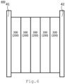
- FIG. 6 illustrate a schematic cross-sectional diagram of stack.
- the stack 400 according to the fourth embodiment illustrated in FIG. 5 is configured so that two or more of the MEAs 200 or the electrochemical cells 300 are connected in series. Tightening plates 41 and 42 are attached to both ends of the electrochemical cells 300.
- the voltage of a single MEA 200 or the electrochemical cell 300 is low. Therefore, high voltage can be obtained by structuring the stack 400 in which two or more of the MEAs 200 or the electrochemical cells 300 are connected in series.
- the amount of hydrogen generated in the electrochemical cell 300 composed of a single MEA 200 is small. Therefore, a large amount of hydrogen can be obtained by structuring the stack 400 in which two or more of the electrochemical cells are connected in series.
- FIG. 7 illustrates a conceptual diagram of the electrolyzer according to the fifth embodiment.
- the electrolyzer 500 uses the electrochemical cell 300 or the stack 400.
- the electrolyzer of FIG. 7 is a water electrolyzer.
- the following is an explanation of an electrolyzer using a water electrolyzer as an example. For example, when hydrogen is generated from ammonia, an apparatus having the other structure using the electrolyte membrane 100 including noble metal particles is preferable.
- water electrolysis cells stacked in series are used as the stack 400 for water electrolysis.
- a power supply 51 is attached to the stack 400, and voltage is applied between the anode and the cathode.
- a gas-liquid separator 52 for separating generated gas and unreacted water and a mixing tank 53 are connected to the anode side of the stack 400 for water electrolysis and water is sent to the mixing tank 53 by a pump 56 from an ion exchanged water producing apparatus 54 that supplies water for mixing in the mixing tank 53, and water is circulated to the anode mixed in the mixed tank 53 through a check valve 57 from the gas-liquid separator 52. Oxygen generated in the anode passes through the gas-liquid separator 52 so that an oxygen gas is obtained.
- a hydrogen purification device 59 is connected to the cathode side subsequent to a gas-liquid separator 58 to obtain high purity hydrogen. Impurities are discharged via a path having a valve 60 connected to the hydrogen purification device 59. In order to control the operating temperature stably, it is possible to control the heating of the stack and a mixing tank, the current density during thermal decomposition, and the like.
- Coating solutions are prepared.
- Solution of the cation noble metal complex oxide salt is adjusted to a predetermined concentration, the predetermined amount of the solution is measured, and the measured solution is adjusted by adding water and water-soluble organic solvent (for example alcohols) to obtain the coating solution.
- water and water-soluble organic solvent for example alcohols
- Nafion115 manufactured by DuPont as cation exchange membrane is fixed on a spray coating apparatus, and the prepared solution of cationic noble metal complex solution is put in a sprayer. Nafion115 is mounted on a rotating drum, and the rotation drum is rotated. While drying with hot air, all the prepared solution is sprayed. A diameter of the rotating drum is 10 [cm], and a rotating speed is 450 [rpm]. After confirming that there is no droplet on the surface on which the solution is sprayed, the cation exchange membrane is washed with ion exchanged water. The spraying conditions are shown in FIG. 2 .
- the washed Nafion115 membrane is immersed at a room temperature (25 [°C]) in 1M of NaBH 4 solution for a predetermined period.
- the cationic noble metal complex ions are reduced to noble metal nano particles to obtain the Nafion115 membrane with dispersed the noble metal nano particles.
- the Nafion115 membrane with dispersed the noble metal nano particles is washed with ion exchanged water.
- the Nafion115 membrane with dispersed the noble metal nano particles is immersed in 10% of nitric oxide which is heated at 40 [°C] and take it out after 2 hours, and the acid treated member is washed sufficiently with ion exchanged water to obtain the Nafion115 membrane with dispersed the noble metal nano particles.
- the membrane manufactured by repeating spraying and drying alternately for the MEA of the water electrolyzer hydrogen leakage is reduced.
- Example 14 Sprayed Amount of Pt [mg/cm 2 ] Injection Pressure of Spraying [Mpa] Immersion Duration in 1 M NaBH 4 [Hour] Amount of Pt in Membrane [mg/cm 2 ] Loading Ratio[%] Comparative Example 0.061 0.5 2 0.0001 0.2 Example 1 0.061 0.3 2 0.0270 44.3 Example 2 0.061 0.5 24 0.0420 68.9 Example 3 0.061 0.5 24 0.0370 60.7 Example 4 0.129 0.5 4 0.0497 38.5 Example 5 0.061 0.3 2 0.0199 32.6 Example 6 0.061 0.3 4 0.0382 62.5 Example 7 0.061 0.3 2 0.0206 33.8 Example 8 0.122 0.3 2 0.0677 55.4 Example 9 0.183 0.3 2 0.0760 41.5 Example 10 0.183 0.3 2 0.1080 59.0 Example 11 0.133 0.5 4 0.0725 54.5 Example 12 0.133 0.5 4 0.0817 61.4 Example 13 0.067 0.5 4 0.0351 52.8 Example 14
- a manufacturing method for electrolyte membrane including noble-metal particles comprising:
- the cationic noble metal complex ion includes one or more kinds of ions of noble metals selected from the group consisting of Pt, Re, Rh, Ir, Pd, and Ru and a neutral molecule as a ligand.
- Clause 4 The manufacturing method according to any one of clauses 1 to 3, wherein the spraying and the drying are performed alternately and repeatedly.
- Clause 5. The manufacturing method according to any one of clauses 1 to 4, wherein hot air at 30 [°C] or more and 120 [°C] or less is applied to the cation exchange membrane in the impregnating the cationic noble metal complex ions.
- Clause 6. The manufacturing method according to any one of clauses 1 to 5, wherein a concentration of the cationic noble metal complex ion in the solution containing the cationic noble metal complex ion is 0.05 [wt%] or more and 5 [wt%] or less.
- Clause 7 The manufacturing method according to any one of clauses 1 to 6, wherein the cation exchange membrane impregnated with the cationic noble metal complex ions is immersed in a reducing solution in the applying the reducing treatment.
- Clause 8 The manufacturing method according to any one of clauses 1 to 7, wherein the cation exchange membrane impregnated with the cationic noble metal complex ions is treated in an atmosphere of heated hydrogen gas in the applying the reducing treatment.
- An electrolyte membrane including noble metal particles comprising:
- Clause 11 The electrolyte membrane according to clause 9 or 10, wherein the cation exchange membrane has sulfonic acid groups.
- a membrane electrode assembly comprising:
- An electrochemical cell comprising: the membrane electrode assembly according to clause 12.
- a stack comprising: the membrane electrode assembly according to clause 12.
- An electrolyzer comprising: the stack according to clause 14.
Landscapes
- Chemical & Material Sciences (AREA)
- Engineering & Computer Science (AREA)
- Chemical Kinetics & Catalysis (AREA)
- Electrochemistry (AREA)
- Materials Engineering (AREA)
- Metallurgy (AREA)
- Organic Chemistry (AREA)
- Inorganic Chemistry (AREA)
- Electrolytic Production Of Non-Metals, Compounds, Apparatuses Therefor (AREA)
- Fuel Cell (AREA)
- Electrodes For Compound Or Non-Metal Manufacture (AREA)
Applications Claiming Priority (1)
| Application Number | Priority Date | Filing Date | Title |
|---|---|---|---|
| JP2022149624A JP7791066B2 (ja) | 2022-09-20 | 2022-09-20 | 貴金属粒子含有電解質膜の製造方法 |
Publications (2)
| Publication Number | Publication Date |
|---|---|
| EP4350052A2 true EP4350052A2 (fr) | 2024-04-10 |
| EP4350052A3 EP4350052A3 (fr) | 2025-05-07 |
Family
ID=88018141
Family Applications (1)
| Application Number | Title | Priority Date | Filing Date |
|---|---|---|---|
| EP23196248.1A Pending EP4350052A3 (fr) | 2022-09-20 | 2023-09-08 | Procédé de fabrication d'une membrane électrolytique comprenant des particules de métal noble, membrane électrolytique comprenant des particules de métal noble |
Country Status (4)
| Country | Link |
|---|---|
| US (1) | US20240102190A1 (fr) |
| EP (1) | EP4350052A3 (fr) |
| JP (2) | JP7791066B2 (fr) |
| AU (1) | AU2023226654B2 (fr) |
Family Cites Families (14)
| Publication number | Priority date | Publication date | Assignee | Title |
|---|---|---|---|---|
| JPS5723080A (en) * | 1980-07-16 | 1982-02-06 | Tokuyama Soda Co Ltd | Preparation of ion exchange membrane-electrode catalyst layer bonded body |
| JPS58181882A (ja) * | 1982-04-14 | 1983-10-24 | Toyo Soda Mfg Co Ltd | 陽イオン交換膜の表面に金属を固着せしめる方法 |
| EP0120212B1 (fr) * | 1983-02-25 | 1986-10-01 | BBC Aktiengesellschaft Brown, Boveri & Cie. | Procédé de production d'une couche électriquement conductrice sur la surface d'un électrolyte solide et couche électriquement conductrice |
| JPH0641639B2 (ja) * | 1989-09-22 | 1994-06-01 | ペルメレック電極株式会社 | 宇宙生命維持装置用水電解装置 |
| JP3395356B2 (ja) * | 1994-05-30 | 2003-04-14 | アイシン精機株式会社 | 燃料電池用電極の製造方法 |
| JPH10102273A (ja) * | 1996-09-27 | 1998-04-21 | Japan Energy Corp | 水電解セル |
| DE10037071A1 (de) * | 2000-07-29 | 2002-02-21 | Omg Ag & Co Kg | Edelmetall-Nanopartikel, Verfahren zu ihrer Herstellung und Verwendung |
| US20150376803A1 (en) * | 2012-10-09 | 2015-12-31 | Brookhaven Science Associates, Llc | Gas Diffusion Electrodes and Methods for Fabricating and Testing Same |
| GB201405210D0 (en) * | 2014-03-24 | 2014-05-07 | Johnson Matthey Fuel Cells Ltd | Process |
| EP3739678A1 (fr) * | 2019-05-17 | 2020-11-18 | Paul Scherrer Institut | Procédé de préparation d'une membrane polymère pour un électrolyseur d'eau électrolyte de polymère |
| EP3748039A1 (fr) * | 2019-06-07 | 2020-12-09 | Hahn-Schickard-Gesellschaft für angewandte Forschung e.V. | Nano-fibres électro-conductrices pour une électrolyse à base de membrane polymère |
| JP2021197207A (ja) * | 2020-06-09 | 2021-12-27 | 矢崎総業株式会社 | 端子、及び端子製造方法 |
| CN113517449B (zh) * | 2021-04-15 | 2023-07-07 | 中国船舶重工集团公司第七一八研究所 | 一种膜电极组件及制备方法 |
| JP7802639B2 (ja) * | 2022-09-20 | 2026-01-20 | 株式会社東芝 | 膜電極接合体、電気化学セル、スタック、電解装置 |
-
2022
- 2022-09-20 JP JP2022149624A patent/JP7791066B2/ja active Active
-
2023
- 2023-09-05 AU AU2023226654A patent/AU2023226654B2/en active Active
- 2023-09-07 US US18/462,942 patent/US20240102190A1/en active Pending
- 2023-09-08 EP EP23196248.1A patent/EP4350052A3/fr active Pending
-
2025
- 2025-12-05 JP JP2025236134A patent/JP2026031727A/ja active Pending
Also Published As
| Publication number | Publication date |
|---|---|
| AU2023226654B2 (en) | 2025-08-14 |
| JP2026031727A (ja) | 2026-02-24 |
| JP7791066B2 (ja) | 2025-12-23 |
| AU2023226654A1 (en) | 2024-04-04 |
| JP2024044221A (ja) | 2024-04-02 |
| US20240102190A1 (en) | 2024-03-28 |
| EP4350052A3 (fr) | 2025-05-07 |
Similar Documents
| Publication | Publication Date | Title |
|---|---|---|
| KR100382801B1 (ko) | 연료 전지용 전극의 제조 방법 및 이로부터 제조된 전극 | |
| US6740434B2 (en) | Organic fuel cell methods and apparatus | |
| US20150236354A1 (en) | COLLOIDAL DISPERSIONS COMPRISING PRECIOUS METAL PARTICLES AND ACIDIC lONOMER COMPONENTS AND METHODS OF THEIR MANUFACTURE AND USE | |
| US20240218538A1 (en) | High surface area, high porosity iridium-based catalyst and method of making | |
| US7931935B2 (en) | Process for producing membrane electrode assembly, and fuel cell using the membrane electrode assembly produced by the process | |
| US20230366112A1 (en) | Method of preparing metal oxide catalysts for oxygen evolution | |
| EP4350052A2 (fr) | Procédé de fabrication d'une membrane électrolytique comprenant des particules de métal noble, membrane électrolytique comprenant des particules de métal noble | |
| US11515554B2 (en) | Membrane electrode assembly and solid polymer fuel cell | |
| KR100754380B1 (ko) | 연료전지용 촉매 및 이를 이용한 연료전지 | |
| EP4565365A1 (fr) | Catalyseur à base d'iridium, à surface spécifique élevée, à porosité élevée et son procédé de fabrication | |
| JP2024016322A (ja) | 触媒 | |
| JP2000106200A (ja) | ガス拡散電極−電解質膜接合体および燃料電池 | |
| US20240200209A1 (en) | In-situ deposition-polymerization for the impregnation and coating of cu-nanoparticle electrodes | |
| US20250333856A1 (en) | Mea for carbon dioxide reduction including reduction catalyst layer cathode of double-layer structure, assembly for carbon dioxide reduction including the mea, and method for preparing the mea | |
| US20260074239A1 (en) | Fuel cell | |
| EP4431642A1 (fr) | Membrane, membrane composite, ensemble membrane-électrode et dispositif d'électrolyse de l'eau | |
| JP2025138161A (ja) | 膜・触媒層接合体および水電解装置 | |
| KR100420375B1 (ko) | 퍼플루오로옥탄술폰산이 첨가된 연료를 사용하는 액체공급 연료 전지 | |
| KR20240137188A (ko) | 막-전극 접합체용 전해질막 및 이의 제조방법 | |
| JP2026017255A (ja) | 膜・触媒層接合体、水電解装置、および膜・触媒層接合体の製造方法 | |
| KR100420374B1 (ko) | 액체 공급 연료 전지 및 이에 사용되는 전극 |
Legal Events
| Date | Code | Title | Description |
|---|---|---|---|
| PUAI | Public reference made under article 153(3) epc to a published international application that has entered the european phase |
Free format text: ORIGINAL CODE: 0009012 |
|
| STAA | Information on the status of an ep patent application or granted ep patent |
Free format text: STATUS: REQUEST FOR EXAMINATION WAS MADE |
|
| 17P | Request for examination filed |
Effective date: 20230908 |
|
| AK | Designated contracting states |
Kind code of ref document: A2 Designated state(s): AL AT BE BG CH CY CZ DE DK EE ES FI FR GB GR HR HU IE IS IT LI LT LU LV MC ME MK MT NL NO PL PT RO RS SE SI SK SM TR |
|
| RIC1 | Information provided on ipc code assigned before grant |
Ipc: C25B 13/08 20060101ALI20241009BHEP Ipc: C25B 13/05 20210101ALI20241009BHEP Ipc: C25B 13/04 20210101ALI20241009BHEP Ipc: C25B 11/081 20210101ALI20241009BHEP Ipc: C25B 11/073 20210101ALI20241009BHEP Ipc: C25B 9/23 20210101AFI20241009BHEP |
|
| PUAL | Search report despatched |
Free format text: ORIGINAL CODE: 0009013 |
|
| AK | Designated contracting states |
Kind code of ref document: A3 Designated state(s): AL AT BE BG CH CY CZ DE DK EE ES FI FR GB GR HR HU IE IS IT LI LT LU LV MC ME MK MT NL NO PL PT RO RS SE SI SK SM TR |
|
| RIC1 | Information provided on ipc code assigned before grant |
Ipc: C25B 13/08 20060101ALI20250328BHEP Ipc: C25B 13/05 20210101ALI20250328BHEP Ipc: C25B 13/04 20210101ALI20250328BHEP Ipc: C25B 11/081 20210101ALI20250328BHEP Ipc: C25B 11/073 20210101ALI20250328BHEP Ipc: C25B 9/23 20210101AFI20250328BHEP |