EP4350088A1 - Machine hydraulique avec bras pivotant autour d'un axe de pivotement - Google Patents
Machine hydraulique avec bras pivotant autour d'un axe de pivotement Download PDFInfo
- Publication number
- EP4350088A1 EP4350088A1 EP23199950.9A EP23199950A EP4350088A1 EP 4350088 A1 EP4350088 A1 EP 4350088A1 EP 23199950 A EP23199950 A EP 23199950A EP 4350088 A1 EP4350088 A1 EP 4350088A1
- Authority
- EP
- European Patent Office
- Prior art keywords
- hydraulic
- lowering
- lifting cylinder
- control element
- machine according
- Prior art date
- Legal status (The legal status is an assumption and is not a legal conclusion. Google has not performed a legal analysis and makes no representation as to the accuracy of the status listed.)
- Pending
Links
Images


Classifications
-
- E—FIXED CONSTRUCTIONS
- E02—HYDRAULIC ENGINEERING; FOUNDATIONS; SOIL SHIFTING
- E02F—DREDGING; SOIL-SHIFTING
- E02F9/00—Component parts of dredgers or soil-shifting machines, not restricted to one of the kinds covered by groups E02F3/00 - E02F7/00
- E02F9/20—Drives; Control devices
- E02F9/22—Hydraulic or pneumatic drives
- E02F9/2203—Arrangements for controlling the attitude of actuators, e.g. speed, floating function
-
- B—PERFORMING OPERATIONS; TRANSPORTING
- B66—HOISTING; LIFTING; HAULING
- B66F—HOISTING, LIFTING, HAULING OR PUSHING, NOT OTHERWISE PROVIDED FOR, e.g. DEVICES WHICH APPLY A LIFTING OR PUSHING FORCE DIRECTLY TO THE SURFACE OF A LOAD
- B66F9/00—Devices for lifting or lowering bulky or heavy goods for loading or unloading purposes
- B66F9/06—Devices for lifting or lowering bulky or heavy goods for loading or unloading purposes movable, with their loads, on wheels or the like, e.g. fork-lift trucks
- B66F9/065—Devices for lifting or lowering bulky or heavy goods for loading or unloading purposes movable, with their loads, on wheels or the like, e.g. fork-lift trucks non-masted
- B66F9/0655—Devices for lifting or lowering bulky or heavy goods for loading or unloading purposes movable, with their loads, on wheels or the like, e.g. fork-lift trucks non-masted with a telescopic boom
-
- B—PERFORMING OPERATIONS; TRANSPORTING
- B66—HOISTING; LIFTING; HAULING
- B66F—HOISTING, LIFTING, HAULING OR PUSHING, NOT OTHERWISE PROVIDED FOR, e.g. DEVICES WHICH APPLY A LIFTING OR PUSHING FORCE DIRECTLY TO THE SURFACE OF A LOAD
- B66F9/00—Devices for lifting or lowering bulky or heavy goods for loading or unloading purposes
- B66F9/06—Devices for lifting or lowering bulky or heavy goods for loading or unloading purposes movable, with their loads, on wheels or the like, e.g. fork-lift trucks
- B66F9/075—Constructional features or details
- B66F9/20—Means for actuating or controlling masts, platforms, or forks
- B66F9/22—Hydraulic devices or systems
-
- E—FIXED CONSTRUCTIONS
- E02—HYDRAULIC ENGINEERING; FOUNDATIONS; SOIL SHIFTING
- E02F—DREDGING; SOIL-SHIFTING
- E02F9/00—Component parts of dredgers or soil-shifting machines, not restricted to one of the kinds covered by groups E02F3/00 - E02F7/00
- E02F9/20—Drives; Control devices
- E02F9/22—Hydraulic or pneumatic drives
- E02F9/2217—Hydraulic or pneumatic drives with energy recovery arrangements, e.g. using accumulators, flywheels
-
- E—FIXED CONSTRUCTIONS
- E02—HYDRAULIC ENGINEERING; FOUNDATIONS; SOIL SHIFTING
- E02F—DREDGING; SOIL-SHIFTING
- E02F9/00—Component parts of dredgers or soil-shifting machines, not restricted to one of the kinds covered by groups E02F3/00 - E02F7/00
- E02F9/20—Drives; Control devices
- E02F9/22—Hydraulic or pneumatic drives
- E02F9/2221—Control of flow rate; Load sensing arrangements
- E02F9/2225—Control of flow rate; Load sensing arrangements using pressure-compensating valves
- E02F9/2228—Control of flow rate; Load sensing arrangements using pressure-compensating valves including an electronic controller
-
- F—MECHANICAL ENGINEERING; LIGHTING; HEATING; WEAPONS; BLASTING
- F15—FLUID-PRESSURE ACTUATORS; HYDRAULICS OR PNEUMATICS IN GENERAL
- F15B—SYSTEMS ACTING BY MEANS OF FLUIDS IN GENERAL; FLUID-PRESSURE ACTUATORS, e.g. SERVOMOTORS; DETAILS OF FLUID-PRESSURE SYSTEMS, NOT OTHERWISE PROVIDED FOR
- F15B11/00—Servomotor systems without provision for follow-up action; Circuits therefor
- F15B11/02—Systems essentially incorporating special features for controlling the speed or actuating force of an output member
- F15B11/024—Systems essentially incorporating special features for controlling the speed or actuating force of an output member by means of differential connection of the servomotor lines, e.g. regenerative circuits
-
- F—MECHANICAL ENGINEERING; LIGHTING; HEATING; WEAPONS; BLASTING
- F15—FLUID-PRESSURE ACTUATORS; HYDRAULICS OR PNEUMATICS IN GENERAL
- F15B—SYSTEMS ACTING BY MEANS OF FLUIDS IN GENERAL; FLUID-PRESSURE ACTUATORS, e.g. SERVOMOTORS; DETAILS OF FLUID-PRESSURE SYSTEMS, NOT OTHERWISE PROVIDED FOR
- F15B11/00—Servomotor systems without provision for follow-up action; Circuits therefor
- F15B11/02—Systems essentially incorporating special features for controlling the speed or actuating force of an output member
- F15B11/04—Systems essentially incorporating special features for controlling the speed or actuating force of an output member for controlling the speed
- F15B11/044—Systems essentially incorporating special features for controlling the speed or actuating force of an output member for controlling the speed by means in the return line, i.e. "meter out"
-
- F—MECHANICAL ENGINEERING; LIGHTING; HEATING; WEAPONS; BLASTING
- F15—FLUID-PRESSURE ACTUATORS; HYDRAULICS OR PNEUMATICS IN GENERAL
- F15B—SYSTEMS ACTING BY MEANS OF FLUIDS IN GENERAL; FLUID-PRESSURE ACTUATORS, e.g. SERVOMOTORS; DETAILS OF FLUID-PRESSURE SYSTEMS, NOT OTHERWISE PROVIDED FOR
- F15B11/00—Servomotor systems without provision for follow-up action; Circuits therefor
- F15B11/16—Servomotor systems without provision for follow-up action; Circuits therefor with two or more servomotors
- F15B11/161—Servomotor systems without provision for follow-up action; Circuits therefor with two or more servomotors with sensing of servomotor demand or load
- F15B11/165—Servomotor systems without provision for follow-up action; Circuits therefor with two or more servomotors with sensing of servomotor demand or load for adjusting the pump output or bypass in response to demand
-
- F—MECHANICAL ENGINEERING; LIGHTING; HEATING; WEAPONS; BLASTING
- F15—FLUID-PRESSURE ACTUATORS; HYDRAULICS OR PNEUMATICS IN GENERAL
- F15B—SYSTEMS ACTING BY MEANS OF FLUIDS IN GENERAL; FLUID-PRESSURE ACTUATORS, e.g. SERVOMOTORS; DETAILS OF FLUID-PRESSURE SYSTEMS, NOT OTHERWISE PROVIDED FOR
- F15B21/00—Common features of fluid actuator systems; Fluid-pressure actuator systems or details thereof, not covered by any other group of this subclass
- F15B21/14—Energy-recuperation means
-
- F—MECHANICAL ENGINEERING; LIGHTING; HEATING; WEAPONS; BLASTING
- F15—FLUID-PRESSURE ACTUATORS; HYDRAULICS OR PNEUMATICS IN GENERAL
- F15B—SYSTEMS ACTING BY MEANS OF FLUIDS IN GENERAL; FLUID-PRESSURE ACTUATORS, e.g. SERVOMOTORS; DETAILS OF FLUID-PRESSURE SYSTEMS, NOT OTHERWISE PROVIDED FOR
- F15B2211/00—Circuits for servomotor systems
- F15B2211/20—Fluid pressure source, e.g. accumulator or variable axial piston pump
- F15B2211/205—Systems with pumps
- F15B2211/2053—Type of pump
- F15B2211/20538—Type of pump constant capacity
-
- F—MECHANICAL ENGINEERING; LIGHTING; HEATING; WEAPONS; BLASTING
- F15—FLUID-PRESSURE ACTUATORS; HYDRAULICS OR PNEUMATICS IN GENERAL
- F15B—SYSTEMS ACTING BY MEANS OF FLUIDS IN GENERAL; FLUID-PRESSURE ACTUATORS, e.g. SERVOMOTORS; DETAILS OF FLUID-PRESSURE SYSTEMS, NOT OTHERWISE PROVIDED FOR
- F15B2211/00—Circuits for servomotor systems
- F15B2211/20—Fluid pressure source, e.g. accumulator or variable axial piston pump
- F15B2211/205—Systems with pumps
- F15B2211/2053—Type of pump
- F15B2211/20546—Type of pump variable capacity
-
- F—MECHANICAL ENGINEERING; LIGHTING; HEATING; WEAPONS; BLASTING
- F15—FLUID-PRESSURE ACTUATORS; HYDRAULICS OR PNEUMATICS IN GENERAL
- F15B—SYSTEMS ACTING BY MEANS OF FLUIDS IN GENERAL; FLUID-PRESSURE ACTUATORS, e.g. SERVOMOTORS; DETAILS OF FLUID-PRESSURE SYSTEMS, NOT OTHERWISE PROVIDED FOR
- F15B2211/00—Circuits for servomotor systems
- F15B2211/20—Fluid pressure source, e.g. accumulator or variable axial piston pump
- F15B2211/21—Systems with pressure sources other than pumps, e.g. with a pyrotechnical charge
- F15B2211/212—Systems with pressure sources other than pumps, e.g. with a pyrotechnical charge the pressure sources being accumulators
-
- F—MECHANICAL ENGINEERING; LIGHTING; HEATING; WEAPONS; BLASTING
- F15—FLUID-PRESSURE ACTUATORS; HYDRAULICS OR PNEUMATICS IN GENERAL
- F15B—SYSTEMS ACTING BY MEANS OF FLUIDS IN GENERAL; FLUID-PRESSURE ACTUATORS, e.g. SERVOMOTORS; DETAILS OF FLUID-PRESSURE SYSTEMS, NOT OTHERWISE PROVIDED FOR
- F15B2211/00—Circuits for servomotor systems
- F15B2211/30—Directional control
- F15B2211/305—Directional control characterised by the type of valves
- F15B2211/30505—Non-return valves, i.e. check valves
-
- F—MECHANICAL ENGINEERING; LIGHTING; HEATING; WEAPONS; BLASTING
- F15—FLUID-PRESSURE ACTUATORS; HYDRAULICS OR PNEUMATICS IN GENERAL
- F15B—SYSTEMS ACTING BY MEANS OF FLUIDS IN GENERAL; FLUID-PRESSURE ACTUATORS, e.g. SERVOMOTORS; DETAILS OF FLUID-PRESSURE SYSTEMS, NOT OTHERWISE PROVIDED FOR
- F15B2211/00—Circuits for servomotor systems
- F15B2211/30—Directional control
- F15B2211/305—Directional control characterised by the type of valves
- F15B2211/3056—Assemblies of multiple valves
- F15B2211/30565—Assemblies of multiple valves having multiple valves for a single output member, e.g. for creating higher valve function by use of multiple valves like two 2/2-valves replacing a 5/3-valve
- F15B2211/3058—Assemblies of multiple valves having multiple valves for a single output member, e.g. for creating higher valve function by use of multiple valves like two 2/2-valves replacing a 5/3-valve having additional valves for interconnecting the fluid chambers of a double-acting actuator, e.g. for regeneration mode or for floating mode
-
- F—MECHANICAL ENGINEERING; LIGHTING; HEATING; WEAPONS; BLASTING
- F15—FLUID-PRESSURE ACTUATORS; HYDRAULICS OR PNEUMATICS IN GENERAL
- F15B—SYSTEMS ACTING BY MEANS OF FLUIDS IN GENERAL; FLUID-PRESSURE ACTUATORS, e.g. SERVOMOTORS; DETAILS OF FLUID-PRESSURE SYSTEMS, NOT OTHERWISE PROVIDED FOR
- F15B2211/00—Circuits for servomotor systems
- F15B2211/40—Flow control
- F15B2211/405—Flow control characterised by the type of flow control means or valve
- F15B2211/40515—Flow control characterised by the type of flow control means or valve with variable throttles or orifices
-
- F—MECHANICAL ENGINEERING; LIGHTING; HEATING; WEAPONS; BLASTING
- F15—FLUID-PRESSURE ACTUATORS; HYDRAULICS OR PNEUMATICS IN GENERAL
- F15B—SYSTEMS ACTING BY MEANS OF FLUIDS IN GENERAL; FLUID-PRESSURE ACTUATORS, e.g. SERVOMOTORS; DETAILS OF FLUID-PRESSURE SYSTEMS, NOT OTHERWISE PROVIDED FOR
- F15B2211/00—Circuits for servomotor systems
- F15B2211/40—Flow control
- F15B2211/41—Flow control characterised by the positions of the valve element
- F15B2211/413—Flow control characterised by the positions of the valve element the positions being continuously variable, e.g. as realised by proportional valves
-
- F—MECHANICAL ENGINEERING; LIGHTING; HEATING; WEAPONS; BLASTING
- F15—FLUID-PRESSURE ACTUATORS; HYDRAULICS OR PNEUMATICS IN GENERAL
- F15B—SYSTEMS ACTING BY MEANS OF FLUIDS IN GENERAL; FLUID-PRESSURE ACTUATORS, e.g. SERVOMOTORS; DETAILS OF FLUID-PRESSURE SYSTEMS, NOT OTHERWISE PROVIDED FOR
- F15B2211/00—Circuits for servomotor systems
- F15B2211/40—Flow control
- F15B2211/415—Flow control characterised by the connections of the flow control means in the circuit
- F15B2211/41527—Flow control characterised by the connections of the flow control means in the circuit being connected to an output member and a directional control valve
-
- F—MECHANICAL ENGINEERING; LIGHTING; HEATING; WEAPONS; BLASTING
- F15—FLUID-PRESSURE ACTUATORS; HYDRAULICS OR PNEUMATICS IN GENERAL
- F15B—SYSTEMS ACTING BY MEANS OF FLUIDS IN GENERAL; FLUID-PRESSURE ACTUATORS, e.g. SERVOMOTORS; DETAILS OF FLUID-PRESSURE SYSTEMS, NOT OTHERWISE PROVIDED FOR
- F15B2211/00—Circuits for servomotor systems
- F15B2211/40—Flow control
- F15B2211/42—Flow control characterised by the type of actuation
- F15B2211/426—Flow control characterised by the type of actuation electrically or electronically
-
- F—MECHANICAL ENGINEERING; LIGHTING; HEATING; WEAPONS; BLASTING
- F15—FLUID-PRESSURE ACTUATORS; HYDRAULICS OR PNEUMATICS IN GENERAL
- F15B—SYSTEMS ACTING BY MEANS OF FLUIDS IN GENERAL; FLUID-PRESSURE ACTUATORS, e.g. SERVOMOTORS; DETAILS OF FLUID-PRESSURE SYSTEMS, NOT OTHERWISE PROVIDED FOR
- F15B2211/00—Circuits for servomotor systems
- F15B2211/40—Flow control
- F15B2211/46—Control of flow in the return line, i.e. meter-out control
-
- F—MECHANICAL ENGINEERING; LIGHTING; HEATING; WEAPONS; BLASTING
- F15—FLUID-PRESSURE ACTUATORS; HYDRAULICS OR PNEUMATICS IN GENERAL
- F15B—SYSTEMS ACTING BY MEANS OF FLUIDS IN GENERAL; FLUID-PRESSURE ACTUATORS, e.g. SERVOMOTORS; DETAILS OF FLUID-PRESSURE SYSTEMS, NOT OTHERWISE PROVIDED FOR
- F15B2211/00—Circuits for servomotor systems
- F15B2211/60—Circuit components or control therefor
- F15B2211/63—Electronic controllers
- F15B2211/6303—Electronic controllers using input signals
- F15B2211/6306—Electronic controllers using input signals representing a pressure
- F15B2211/6313—Electronic controllers using input signals representing a pressure the pressure being a load pressure
-
- F—MECHANICAL ENGINEERING; LIGHTING; HEATING; WEAPONS; BLASTING
- F15—FLUID-PRESSURE ACTUATORS; HYDRAULICS OR PNEUMATICS IN GENERAL
- F15B—SYSTEMS ACTING BY MEANS OF FLUIDS IN GENERAL; FLUID-PRESSURE ACTUATORS, e.g. SERVOMOTORS; DETAILS OF FLUID-PRESSURE SYSTEMS, NOT OTHERWISE PROVIDED FOR
- F15B2211/00—Circuits for servomotor systems
- F15B2211/70—Output members, e.g. hydraulic motors or cylinders or control therefor
- F15B2211/705—Output members, e.g. hydraulic motors or cylinders or control therefor characterised by the type of output members or actuators
- F15B2211/7051—Linear output members
- F15B2211/7053—Double-acting output members
-
- F—MECHANICAL ENGINEERING; LIGHTING; HEATING; WEAPONS; BLASTING
- F15—FLUID-PRESSURE ACTUATORS; HYDRAULICS OR PNEUMATICS IN GENERAL
- F15B—SYSTEMS ACTING BY MEANS OF FLUIDS IN GENERAL; FLUID-PRESSURE ACTUATORS, e.g. SERVOMOTORS; DETAILS OF FLUID-PRESSURE SYSTEMS, NOT OTHERWISE PROVIDED FOR
- F15B2211/00—Circuits for servomotor systems
- F15B2211/70—Output members, e.g. hydraulic motors or cylinders or control therefor
- F15B2211/71—Multiple output members, e.g. multiple hydraulic motors or cylinders
-
- F—MECHANICAL ENGINEERING; LIGHTING; HEATING; WEAPONS; BLASTING
- F15—FLUID-PRESSURE ACTUATORS; HYDRAULICS OR PNEUMATICS IN GENERAL
- F15B—SYSTEMS ACTING BY MEANS OF FLUIDS IN GENERAL; FLUID-PRESSURE ACTUATORS, e.g. SERVOMOTORS; DETAILS OF FLUID-PRESSURE SYSTEMS, NOT OTHERWISE PROVIDED FOR
- F15B2211/00—Circuits for servomotor systems
- F15B2211/70—Output members, e.g. hydraulic motors or cylinders or control therefor
- F15B2211/76—Control of force or torque of the output member
- F15B2211/761—Control of a negative load, i.e. of a load generating hydraulic energy
Definitions
- the invention relates to a hydraulic machine, in particular a motor vehicle such as an excavator, wheel loader, tractor, telescopic loader or the like, with a boom that can be pivoted about a pivot axis with respect to a frame, wherein a lifting cylinder having a piston and a piston rod is provided for pivoting the boom relative to the frame, wherein at least one lifting cylinder control element that can be controlled by means of a control unit is provided for controlling the lifting cylinder and/or for switching between a lowering operation for lowering the boom and/or a lifting operation for raising the boom and/or a holding operation for holding the boom, wherein the lifting cylinder is designed as a first hydraulic consumer and at least one second hydraulic consumer is provided.
- a motor vehicle such as an excavator, wheel loader, tractor, telescopic loader or the like
- vehicles such as excavators, wheel loaders, telescopic loaders, snow groomers, tractors, combine harvesters, forage harvesters, forestry/hauling cranes, so-called “harvesters”, front loaders, etc. have been in use for years in civil engineering, recycling and waste management, gardening and landscaping, as well as in forestry or agriculture, where various loads or tools can be attached to a boom or swivel arm.
- other tools such as load hooks, concrete buckets, Sweeper, work platform, cable winch, dozer blade and grapple are used. So-called quick-change plates are available to enable quick tool changes.
- loading systems on telehandlers have a lifting arm with at least one extension stage, which is usually pivotally mounted at the rear of the vehicle.
- the raising and lowering of the boom or lifting arm is carried out by a hydraulic lifting cylinder, which is controlled or operated by the driver using a control/directional valve.
- a lowering brake valve is normally used for the controlled lowering of the load.
- the control valve and the lowering brake valve are usually controlled with the same pilot pressure. This directs an oil flow from a hydraulic pump, i.e. on the so-called supply side or in the so-called feed line or in particular by means of/in a first connecting device, via the control valve to the rod side of the lifting cylinder.
- the lowering brake valve opens and directs the oil displaced from the piston side via the control valve to the tank or hydraulic accumulator, in particular in the so-called return line or by means of/in a second connecting device. This sets the lifting cylinder in motion and the load is lowered. Due to the shared control, the characteristics of the control valve and lowering brake valve must be precisely coordinated with one another.
- the lowering brake valve is currently operated via a hydraulic pilot signal.
- the pilot pressure required for control is provided by a pressure reducing valve, which is connected to a provides a pressure proportional to the control current. Due to its geometric design, the lowering brake valve is load-compensated, ie, regardless of the load, approximately the same volume flow is achieved through the valve.
- a so-called "regeneration” can also be integrated, e.g. EP 1 915 538 B1
- the piston and rod sides of the lifting cylinder are also connected to each other when the load is lowered. Due to the unequal effective areas, part of the oil quantity is directed from the piston to the rod side. The excess oil quantity flows to the tank via the control valve. This reduces the oil flow supplied to the pump and saves energy to a certain extent.
- a disadvantage of the hydraulic machines known to date is that the control valve must provide a slightly larger oil flow than the lowering brake valve releases for drainage under load. Due to the joint piloting, an exact coordination of the control valve and lowering brake valve is not possible at every operating point. This results in back pressures in front of the lowering brake valve (piston side), which must be overcome in an energy-intensive manner by supplying drive power.
- the object of the invention is to propose a hydraulic machine, in particular a motor vehicle, which realizes an improved or more efficient mode of operation compared to the prior art, in particular has an improved pressurization or energy utilization of the hydraulic system and/or can be retrofitted.
- a third connection device for hydraulic connection is provided between the first connection device and the second connection device, wherein the second and/or third connection device has at least one lowering control element, advantageous energy utilization or regeneration and/or recuperation of the energy of the hydraulic system can be realized.
- the hydraulic connection or third connection device realizes further or reuse of the Hydraulic fluid/oil from one or the first lifting cylinder/consumer to/for another or the second or possibly third lifting cylinder/consumer.
- the hydraulic connection or third connection device is advantageously designed as a consumer connection between at least two consumers or lifting cylinders. The hydraulic connection or third connection device is therefore not for connecting two connections of a single consumer or lifting cylinder, i.e.
- the hydraulic connection can, for example, comprise a pressure line or metal pipe or hydraulic pipe and/or a pressure hose.
- At least one lowering sensor is provided for detecting an actual lowering parameter of the lowering operation, the lowering sensor generating a lowering signal and/or the control unit being designed to actuate the lowering control element, in particular a controllable lowering valve, and/or to switch the controllable lifting cylinder control element depending on the lowering signal, so that the hydraulic oil/fluid can flow from the second connecting device to the first connecting device during the lowering operation.
- the hydraulic system is made significantly more flexible during the lowering process. This makes it possible to achieve a particularly energy-saving and/or automated and/or "more fluid" or more even/continuous lowering operation.
- an advantageous actual lowering parameter can now be recorded during the lowering operation using the advantageous lowering sensor and used for improved lowering operation. This enables improvements to the hydraulic system that were previously not possible, in particular for an energy-saving and/or more continuous lowering operation of the boom.
- the senor can record this actual state or the corresponding actual lowering parameter and use it to advantageously adapt and/or change the lowering process or lowering operation.
- This opens up completely new (more automated) operating options with significantly improved comfort and/or energy consumption.
- the pressure generation unit can be operated less or for a shorter period of time, which can further reduce energy consumption.
- the third connection device is designed as a bypass of the lifting cylinder control element, with a first branching unit in the flow direction of the hydraulic oil/fluid being arranged upstream of the lifting cylinder control element and a second branching unit in the flow direction of the hydraulic oil/fluid being arranged downstream of the lifting cylinder control element.
- the driver/operator can thus actuate/switch the lifting cylinder control element/valve so that, for example, the boom changes from lifting/holding mode to lowering mode, with the lifting cylinder control element/valve being advantageously bypassed in lowering mode and hydraulic oil/fluid flowing through the third connection device or the "hydraulic short circuit" rather than through the lifting cylinder control element.
- the flow direction of the hydraulic oil/fluid through the third connection device is advantageously from the return line to the supply line, whereby the pressure generating device or pump is advantageously bypassed. Accordingly, the pump does not need to generate any or less pressure energy. Instead, the pressure energy of the lowering operation is advantageously made available to the hydraulic system or is retained and made usable for other, particularly later and/or simultaneous hydraulic consumption.
- the third connection device comprises at least one check valve and/or a controllable control element, in particular a directional/proportional valve, and/or the third connection device comprises at least one hydraulic accumulator, in particular a pressure tank, for storing the hydraulic oil/fluid.
- the hydraulic control/monitoring can be improved. For example, It must be effectively prevented, in particular by means of the (electrical and/or electronic) control unit, that hydraulic oil/fluid does not flow through the third connection device or the "hydraulic short circuit" during lifting and/or holding operation of the boom, in particular directly to the " return line " and/or directly to the machine/vehicle tank or hydraulic system reservoir.
- the hydraulic accumulator particularly a pressure tank, can be used to advantageously store hydraulic oil/fluid, particularly under pressure, (temporarily). This opens up new possibilities and is a great advantage.
- the third connection device advantageously comprises at least one hydraulic sensor that generates a hydraulic signal for detecting a hydraulic parameter of the lowering operation and/or the hydraulic accumulator. This makes it particularly easy to determine the lowering operation or to advantageously detect the hydraulic accumulator or its status, such as pressure, filling level, defect or the like.
- a parameter comparison unit generating at least one comparison signal is provided for comparing the actual lowering parameter with the hydraulic parameter, whereby the control unit is designed to actuate the controllable lowering control element, in particular the lowering valve, and/or the controllable control element and/or to switch the controllable lifting cylinder control element depending on this comparison.
- the lowering operation in particular a lowering operation with a particular pressure/lowering parameter, can be advantageously determined and used to operate the machine. For example, it can be determined whether energy utilization or regeneration or recuperation is possible/helpful or advantageous or whether not or only to a limited extent or under which conditions/control measures.
- an actual-target comparison unit generating at least one lowering control signal is provided for comparing the actual lowering parameter with a target and/or limit parameter, whereby depending on this actual-target comparison, the control unit is designed to actuate the controllable lowering control element, in particular the lowering valve, and/or the controllable control element and/or to switch the controllable lifting cylinder control element, so that the hydraulic oil/fluid in the piston rod chamber is pressurized.
- This allows the hydraulic system to be made even more flexible during the lowering process. This makes it possible, among other things, to achieve a particularly energy-saving and/or automated and/or "more fluid" or more even/continuous lowering operation.
- the resulting lowering speed without a load can be too low.
- This can be counteracted in an advantageous manner, for example, by selecting a reference value higher than the holding pressure of the empty loading system.
- active lowering is advantageous when the driving weight of the load and loading system is too low.
- Heavy loads continue to be lowered passively or in an energy-saving manner.
- a lowering sensor and/or the hydraulic sensor is conceivable, which is designed as a speed sensor for detecting a lowering speed, e.g. for detecting the adjustment speed or the retraction of the lifting cylinder, i.e. the piston, or the angular velocity on the swivel axis of the boom.
- the lowering sensor and/or the hydraulic sensor could also be used, for example, as a contact sensor to detect a contact of the boom and/or the load suspension or the tool. It is conceivable that, for example, a resting/standing on the ground, a contact when loading a vehicle trailer or the like could be detected.
- a distance sensor, an optical sensor, a capacitive or inductive sensor, a radar sensor or the like could be conceivable, whereby the distance and/or the contact and/or a reduction/change in the lowering process can be detected.
- the operating conditions during lowering can change considerably, so that the operation of the hydraulic system or lifting cylinder and/or the pump system or the pressure generation unit can be advantageously adapted/changed by means of the advantageous target-actual comparison or the lowering control signal or the lowering parameter according to the invention.
- the lowering sensor and/or the hydraulic sensor is designed as a pressure sensor for detecting a pressure of the hydraulic oil/fluid, in particular the so-called " load pressure " .
- This can be used to detect a change or undershoot/overshoot of the Hydraulic pressure in the hydraulic system or the hydraulic fluid or the hydraulic oil can be advantageously recorded and used according to the invention, in particular the advantageous target-actual comparison.
- This measure enables particularly cost-effective implementation, since a wide variety of pressure sensors for hydraulic systems are already commercially available and therefore inexpensive.
- very small pressure differences/changes can also be recorded and advantageously used according to the invention.
- a load pressure is created on the piston side of the lifting cylinder due to a load being taken up and/or the weight of the loading system or the (entire) boom.
- the load pressure is present even without tools/attachments, mainly due to the weight of the boom or loading system.
- This is also referred to as the holding pressure of the empty loading system.
- the holding pressure is used/defined as a limit/target/reference value for advantageous control or switching according to the invention, e.g.
- At least one regeneration connection line is provided/formed between the piston chamber and the piston rod chamber, so that hydraulic oil/fluid can be supplied from the piston chamber to the piston rod chamber can flow, whereby the regeneration connection line has at least one lowering brake element.
- the regeneration connection line has at least one lowering brake element.
- the pressure sensor is arranged in the regeneration connection line and between the piston chamber and the lowering brake element or in/on the piston chamber. This advantageously allows the pressure of the piston chamber or the lines/sections hydraulically connected to it to be recorded and used advantageously in particular in the event of changes in the actual pressure according to the invention. On the one hand, even the smallest actual parameter changes can be recorded very precisely and, on the other hand, the invention can be implemented in a very compact/space-saving manner.
- the pressure in the piston chamber and/or at least in an adjacent section of the regeneration connection line drops when the boom and/or tool or the load suspension comes into contact with the ground, with an object such as a vehicle trailer, dump truck or the like, which can be recorded according to the invention and used for advantageous control.
- a control device for controlling the lowering control element and/or lowering brake element, wherein the control device is at least partially designed separately from the control unit of the controllable lifting cylinder control element, so that the lowering control element and/or lowering brake element can be controlled separately from the lifting cylinder control element.
- the control device is designed as a control valve, in particular a directional valve, that can be controlled by means of the control unit. This allows the control device and the control unit or the controllable lifting cylinder control element to be operated (largely) independently of one another. This opens up completely new possibilities for control. of the hydraulic system or the lifting cylinder and/or the controllable lifting cylinder control element etc.
- At least one relief element/valve is provided, with at least one branching unit being arranged between the lowering brake element and the lifting cylinder control element, and with the relief element/valve being arranged between the branching unit and a hydraulic accumulator/tank, so that excess hydraulic oil/fluid from the piston chamber can be fed to the hydraulic accumulator/tank during lowering operation.
- the load pressure on the lifting cylinder is usually a good option, whereby it is advantageous to automatically switch between load-induced lowering movement and active lowering of loads, can be used advantageously in hydraulic machines where loads are lifted using hydraulic cylinders and lowering them is not possible without restrictions due to their own weight or where forces must be actively applied in the lowering direction at times.
- the boom or the loading system is advantageously lowered in a controlled manner by using gravity, which leads to a saving in pumping energy and/or an improvement in comfort and/or a more continuous lowering movement.
- the second hydraulic consumer is designed as a hydraulic motor and/or at least one electrical generator is provided for generating electrical current and/or electrical energy
- the pressure generating device or hydraulic pump is designed as a hydraulic motor and/or an electric pump motor of the hydraulic pump is designed as the electric generator.
- the pressure generating device is advantageously designed to pressurize the hydraulic accumulator.
- any "excess" energy from the drive motor, in particular the combustion/diesel engine can be used advantageously to temporarily store pressure energy or hydraulic energy.
- the pressure generating device or hydraulic pump can be made smaller than has previously been the case and can also be more cost-effective. It is therefore conceivable that the pressure generating device or hydraulic pump is not designed for so-called " load peaks " that rarely occur, but that these " load peaks " can be implemented together with the aid of the advantageous hydraulic accumulator.
- the invention can be used to achieve advantageous regeneration and/or recuperation of energy from driving loads. This allows, for example, to support all consumers of the hydraulic circuit/system to a large extent in the same way.
- the resulting system can be implemented very flexibly in different levels of complexity and can be combined with many different system architectures. These include systems with constant and variable pumps driven by diesel engines, as well as systems of electrically operated machines in which the oil supply is provided by means of a constant or variable pump in conjunction with with electric motors with constant or variable speed.
- the system can also be retrofitted as an option without much effort.
- At least one system pressure is continuously evaluated and assessed depending on whether the lifting arm of the machine is lowered under active pressure supply, energy-neutrally or under regeneration or recuperation of potential energy from the movement.
- the invention can be combined very variably with the common hydraulic systems, especially with a so-called "LS reporting chain", without the need for variations of the components of the standard equipment.
- the software functionality of the basic system does not have to be changed significantly with regard to the control unit or machine control. Rather, only the components supplemented by the invention need to be taken into account or supplemented using additional software modules.
- One advantage of the invention is particularly due to the fact that the recovered energy is provided in parallel to the supply pump in such a way that the circuits supplied with it can adapt to the supply of an additional volume flow through their existing basic functionalities.
- a telescopic loader 1 comprises, among other things, a boom 1.1 or a telescopic lifting arm 1.1, which can be adjusted/pivoted about a first pivot axis 1.8 with the aid of a pivot cylinder 2.1 or lifting cylinder 2.1 having a piston 22 and a piston rod 23 in relation to a vehicle frame 1.6.
- This allows the boom arm 1.1 to be adjusted in height.
- the length adjustment can be implemented in a known manner in one or more stages and is not shown or explained in more detail here.
- the telehandler 1 also has, in a known manner, a driver's cabin 1.7, in which one or two or more control elements for driving and for operating the hydraulic system are advantageously present.
- wheels 5 or drive chains (not shown), e.g. of an excavator or the like, are provided in a known manner, which can preferably be driven by means of a drive motor, e.g. diesel motor and/or electric motor and/or hydraulic motor, and/or can be steered by the driver.
- a load receiver 1.3 or tool carrier 1.3 is arranged on the boom 1.1 or telescopic boom arm 1.1 so as to be pivotable about a second pivot axis 1.9.
- a load 1.4 or a tool 1.4 is arranged on one end of the arm 1.5, with the tool carrier 1.3 being tilted or lifted with the aid of a tilting cylinder 3.1 or. Tilting cylinder 3.1 can be adjusted/pivoted in relation to the arm end 1.5.
- the tilting cylinder 3.1 can advantageously be hydraulically connected to a compensation cylinder 4.1 via a first connecting line and a second connecting line (not shown in more detail), i.e. hydraulic fluid/oil can be exchanged via the two connecting lines or they are integrated into a common hydraulic circuit.
- a first connecting line and a second connecting line not shown in more detail
- hydraulic fluid/oil can be exchanged via the two connecting lines or they are integrated into a common hydraulic circuit.
- this ensures that the load 1.4 or the tool 1.4 remains in a predetermined position or orientation, e.g. in a horizontal position, when the boom 1.1 is swiveled, which is usually a great advantage in practice.
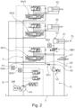
- FIG. 2 to 4 Different embodiments and hydraulic circuit diagrams are shown schematically.
- three lifting cylinders Z1, Z2, Z3, each with a correspondingly assigned directional valve WV1, WV2, WV3, are included as hydraulic consumers.
- the lifting cylinder Z1 should correspond to the swivel cylinder 2.1, ie for raising and lowering the boom 1.1 according to Figure 1
- the lifting cylinder Z2 can be connected to the tilting cylinder 3.1 and the lifting cylinder Z3 can be connected to a Figure 1 telescopic cylinders (not shown) for telescoping the boom 1.1.
- the telehandler 1 may have additional lifting cylinders and/or hydraulic motors, but these are not shown or integrated in the hydraulic circuit diagrams.
- a drive motor in particular an electric motor or diesel engine DM, which drives a pump PV.
- a pump PV in Figure 2 is a variable displacement pump PV and in Figure 3 a constant pump PV is integrated in the known manner.
- a flow line I supplies the above-mentioned lifting cylinders Z1, Z2, Z3 with hydraulic oil/fluid or pressurizes them in the known manner.
- a return line II is provided in the hydraulic circuit in the known manner, which prevents the backflow of the hydraulic oil/fluid into a tank T.
- the three directional valves WV1, WV2, WV3 are provided for the usual hydraulic control of the three lifting cylinders Z1, Z2, Z3.
- There is also a generally standard lowering brake valve SBV for holding raised loads without leaks and for limiting the lowering speed of the lifting cylinder Z1 in the event of a line break.
- a basic functionality of the invention or a third connection device III in the sense of the invention is explained with reference to the Figures 2 and 3 described in more detail below using two different scenarios.
- a load pressure or lowering pressure on the piston bottom side of the lifting cylinder Z1 is recorded via a lowering sensor or a pressure sensor DA1 and is used or evaluated in particular by means of an electrical and/or electronic control unit (not shown in detail). If the pressure is too low to exert a lowering movement against the opposing resistance, the movement is carried out conventionally via the directional control valve WV1.
- the lowering brake valve SBV is controlled independently of the directional control valve WV1, and a 2/2-way valve V1 of the return line II remains unactuated.
- the hydraulic oil/fluid flows back to the tank T via the common return line II, with the common return line II being designed as the return line for all lifting cylinders Z1, Z2, Z3.
- the return line II or the second connecting device in the sense of the invention consists of several return lines.
- the flow line I or the first connecting device in the sense of the invention consists in the present case of a largely common pressure supply, but of course splits upstream of the consumers as usual.
- a sensor can also be arranged directly on the first connecting device I or the flow line I, ie by means of a further sensor or pressure transducer DA3.
- the load pressure on the lifting cylinder Z1 or the sensor DA1 is higher by a sufficient amount than the pressure of the signaling chain/sensor DA2/DA3 or the flow line I, energy from the lowering movement VH can be regenerated into the supply volume flow or the flow line I to the directional control valves WV1, WV2, WV3 or via the third connection device III.
- the directional control valve WV1 is "bridged", namely with the help of the branches A1 and A2 of the third connection device III, so that this forms a bypass with respect to the directional control valve WV1.
- the return flow from the lifting cylinder Z1 is dammed up with the help of an electrically proportional pressure relief valve V3 to such an extent that a volume flow is produced via the third connecting device III or the check valve RV1.
- the amount of oil that must be provided by the pump PV is reduced by the regenerated amount from the lowering movement. If the load pressure level on the lifting cylinder Z1 is not high enough for regeneration, the outflowing volume flow from the cylinder Z1 is led directly to the oil container or tank T by completely relieving the valve V3.
- Figure 4 shows this schematically using the example of the recuperation of the lowering energy in a hydraulic accumulator SH of the third connection device III.
- this hydraulic accumulator SH for example, a delayed use of stored pressure/hydraulic energy to operate other consumers such as the lifting cylinders Z2, Z3 and/or the possible recuperation by means of motor operation of the pump PV/PM.
- the pump PM can be used as a hydraulic motor PM and the drive motor MG or electric motor DM/MG as an electric generator MG in generator operation for the conversion or generation of electrical energy.
- an extension to include the SP storage tank and the V6 and RV2 valves is not absolutely necessary, but is advantageous. However, this allows an expanded range of functions, as energy can be temporarily stored via the SH storage tank of the third connection device III or converted into electrical energy using a generator.
- the returning volume flow from the lifting cylinder Z1 is advantageously dammed up via a proportional pressure relief valve V3 so that the accumulator SH can continue to be filled.
- proportional pressure reducing valve V3 advantageously allows the load pressure on the lifting cylinder Z1 to be increased in a controlled manner by applying pressure to the piston rod side of the cylinder Z1 if this pressure is too low to continue filling the SH accumulator.
- the valve V1 is not activated if possible.
- the accumulator pressure level is adjusted to the required supply pressure of the hydraulic circuit via the valve V6, so that a volume flow is produced from the accumulator SH via the valves V6 and RV2 to the supply side of the consumer circuit or the flow I.
- the effective pressure difference is advantageously determined via the directional valves WV1, WV2, WV3 using the sensors or pressure transducers DA2 and DA3 and is advantageously controlled using a drive speed of the pump PV/PM and the proportional pressure relief valve (V5).
Landscapes
- Engineering & Computer Science (AREA)
- General Engineering & Computer Science (AREA)
- Structural Engineering (AREA)
- Mechanical Engineering (AREA)
- Civil Engineering (AREA)
- Fluid Mechanics (AREA)
- Physics & Mathematics (AREA)
- Transportation (AREA)
- Mining & Mineral Resources (AREA)
- Geology (AREA)
- Life Sciences & Earth Sciences (AREA)
- Chemical & Material Sciences (AREA)
- Combustion & Propulsion (AREA)
- Analytical Chemistry (AREA)
- Fluid-Pressure Circuits (AREA)
Applications Claiming Priority (1)
| Application Number | Priority Date | Filing Date | Title |
|---|---|---|---|
| DE102022126009.7A DE102022126009A1 (de) | 2022-10-07 | 2022-10-07 | Hydraulikmaschine mit einem um eine Schwenkachse verschwenkbaren Ausleger |
Publications (1)
| Publication Number | Publication Date |
|---|---|
| EP4350088A1 true EP4350088A1 (fr) | 2024-04-10 |
Family
ID=88204112
Family Applications (1)
| Application Number | Title | Priority Date | Filing Date |
|---|---|---|---|
| EP23199950.9A Pending EP4350088A1 (fr) | 2022-10-07 | 2023-09-27 | Machine hydraulique avec bras pivotant autour d'un axe de pivotement |
Country Status (2)
| Country | Link |
|---|---|
| EP (1) | EP4350088A1 (fr) |
| DE (1) | DE102022126009A1 (fr) |
Cited By (1)
| Publication number | Priority date | Publication date | Assignee | Title |
|---|---|---|---|---|
| CN119195764A (zh) * | 2024-09-09 | 2024-12-27 | 三一重型装备有限公司 | 自移机尾及其控制方法和控制装置、可读存储介质 |
Citations (7)
| Publication number | Priority date | Publication date | Assignee | Title |
|---|---|---|---|---|
| EP1281872A1 (fr) * | 2001-08-04 | 2003-02-05 | Robert Bosch Gmbh | Dispositif electro-hydraulique pour le contrôle d'un moteur à double effet |
| EP1450048B1 (fr) * | 2003-02-21 | 2006-06-14 | Deere & Company | Agencement de vanne |
| EP1915538B1 (fr) | 2005-08-19 | 2012-04-04 | Bucher Hydraulics AG | Montage pour commander un cylindre d'entrainement hydraulique a double effet |
| DE102014114526A1 (de) * | 2014-10-07 | 2016-04-07 | Linde Material Handling Gmbh | Hydraulisches Antriebssystem einer batterie-betriebenen mobilen Arbeitsmaschine |
| US20180112686A1 (en) | 2016-10-26 | 2018-04-26 | Hydraforce, Inc. | Hydraulic actuator system of vehicle having secondary load-holding valve with tank connection |
| WO2022039697A1 (fr) * | 2020-08-21 | 2022-02-24 | Hi̇dromek-Hi̇droli̇k Ve Mekani̇k Maki̇na İmalat Sanayi̇ Ve Ti̇caret Anoni̇m Şi̇rketi̇ | Système hydraulique pouvant fournir une récupération d'énergie par valves directionnelles double tiroir pendant le basculement/abaissement dans un vérin de godet sur un côté chargeur et dans des vérins de bras/godet sur un côté excavateur dans une chargeuse-pelleteuse, chargeuse sur pneus et machines excavatrices |
| EP4148192A1 (fr) * | 2021-09-08 | 2023-03-15 | Kramer-Werke GmbH | Machine hydraulique dotée d'une flèche pivotante autour d'un axe de pivotement |
Family Cites Families (2)
| Publication number | Priority date | Publication date | Assignee | Title |
|---|---|---|---|---|
| US7269944B2 (en) * | 2005-09-30 | 2007-09-18 | Caterpillar Inc. | Hydraulic system for recovering potential energy |
| DE102016205582A1 (de) * | 2016-04-05 | 2017-10-05 | Robert Bosch Gmbh | Hydraulische Antriebsvorrichtung mit Regenerationsbetrieb |
-
2022
- 2022-10-07 DE DE102022126009.7A patent/DE102022126009A1/de active Pending
-
2023
- 2023-09-27 EP EP23199950.9A patent/EP4350088A1/fr active Pending
Patent Citations (7)
| Publication number | Priority date | Publication date | Assignee | Title |
|---|---|---|---|---|
| EP1281872A1 (fr) * | 2001-08-04 | 2003-02-05 | Robert Bosch Gmbh | Dispositif electro-hydraulique pour le contrôle d'un moteur à double effet |
| EP1450048B1 (fr) * | 2003-02-21 | 2006-06-14 | Deere & Company | Agencement de vanne |
| EP1915538B1 (fr) | 2005-08-19 | 2012-04-04 | Bucher Hydraulics AG | Montage pour commander un cylindre d'entrainement hydraulique a double effet |
| DE102014114526A1 (de) * | 2014-10-07 | 2016-04-07 | Linde Material Handling Gmbh | Hydraulisches Antriebssystem einer batterie-betriebenen mobilen Arbeitsmaschine |
| US20180112686A1 (en) | 2016-10-26 | 2018-04-26 | Hydraforce, Inc. | Hydraulic actuator system of vehicle having secondary load-holding valve with tank connection |
| WO2022039697A1 (fr) * | 2020-08-21 | 2022-02-24 | Hi̇dromek-Hi̇droli̇k Ve Mekani̇k Maki̇na İmalat Sanayi̇ Ve Ti̇caret Anoni̇m Şi̇rketi̇ | Système hydraulique pouvant fournir une récupération d'énergie par valves directionnelles double tiroir pendant le basculement/abaissement dans un vérin de godet sur un côté chargeur et dans des vérins de bras/godet sur un côté excavateur dans une chargeuse-pelleteuse, chargeuse sur pneus et machines excavatrices |
| EP4148192A1 (fr) * | 2021-09-08 | 2023-03-15 | Kramer-Werke GmbH | Machine hydraulique dotée d'une flèche pivotante autour d'un axe de pivotement |
Cited By (1)
| Publication number | Priority date | Publication date | Assignee | Title |
|---|---|---|---|---|
| CN119195764A (zh) * | 2024-09-09 | 2024-12-27 | 三一重型装备有限公司 | 自移机尾及其控制方法和控制装置、可读存储介质 |
Also Published As
| Publication number | Publication date |
|---|---|
| DE102022126009A1 (de) | 2024-04-18 |
Similar Documents
| Publication | Publication Date | Title |
|---|---|---|
| DE4132597C2 (de) | Verfahren und Vorrichtung zur Steuerung eines Baggers | |
| DE4136084C2 (de) | Verfahren und Vorrichtung zur Steuerung eines Baggers | |
| EP4148192B1 (fr) | Machine hydraulique dotée d'une flèche pivotante autour d'un axe de pivotement | |
| EP1897847B1 (fr) | Appareil de chargement | |
| DE112013002784T5 (de) | Elektrohydraulisches System zur Wiedergewinnung und Wiederverwendung potenzieller Energie | |
| DE10315071A1 (de) | Hydraulisches Regenerationssystem | |
| EP1752587B1 (fr) | Agencement hydraulique | |
| DE10393484B4 (de) | Verfahren und Vorrichtung zur Steuerung einer Hydraulikpumpe für ein Arbeitsgerät eines Arbeitsfahrzeuges | |
| DE112011104435T5 (de) | Hydrauliksteuersystem mit Energiewiedergewinnung | |
| DE112012005272T5 (de) | Hydrauliksystem mit Energierückgewinnung | |
| DE10230993A1 (de) | Verfahren und Vorrichtung zur Steuerung von Funktionen eines Arbeitsfahrzeuges | |
| EP1574626B1 (fr) | Système hydraulique de suspension passive | |
| DE112015000263T5 (de) | Flussregeneration für Auslegerzylinder beim Grabvorgang | |
| DE102005033154A1 (de) | Hydraulische Anordnung | |
| EP4350088A1 (fr) | Machine hydraulique avec bras pivotant autour d'un axe de pivotement | |
| EP3517790A1 (fr) | Machine de travail pourvu d'hydraulique destinée à la récupération d'énergie | |
| DE10012389B4 (de) | Arbeitsmaschine | |
| DE102017213118A1 (de) | Ventilblockanordnung und Verfahren für eine Ventilblockanordnung | |
| DE202019105397U1 (de) | Sicherheitseinrichtung für Baumaschinen und dergleichen | |
| DE19654700A1 (de) | Fahrzeughydrauliksystem | |
| EP1440211B1 (fr) | Engin de travail et procede pour faire fonctionner un engin de travail | |
| DE202022104585U1 (de) | Mobile Arbeitsmaschine mit einem Arbeitswerkzeug und einer Kontrolleinheit | |
| EP4402381A1 (fr) | Ensemble de commande électro-hydraulique économe en énergie | |
| EP2341190B1 (fr) | Engin mobil avec un agencement hydraulique | |
| EP1918462A2 (fr) | Engin de construction doté d'un système de transmission et d'un système de positionnement ainsi que sa méthode de fonctionnement |
Legal Events
| Date | Code | Title | Description |
|---|---|---|---|
| PUAI | Public reference made under article 153(3) epc to a published international application that has entered the european phase |
Free format text: ORIGINAL CODE: 0009012 |
|
| STAA | Information on the status of an ep patent application or granted ep patent |
Free format text: STATUS: THE APPLICATION HAS BEEN PUBLISHED |
|
| AK | Designated contracting states |
Kind code of ref document: A1 Designated state(s): AL AT BE BG CH CY CZ DE DK EE ES FI FR GB GR HR HU IE IS IT LI LT LU LV MC ME MK MT NL NO PL PT RO RS SE SI SK SM TR |
|
| STAA | Information on the status of an ep patent application or granted ep patent |
Free format text: STATUS: REQUEST FOR EXAMINATION WAS MADE |
|
| 17P | Request for examination filed |
Effective date: 20241008 |
|
| RBV | Designated contracting states (corrected) |
Designated state(s): AL AT BE BG CH CY CZ DE DK EE ES FI FR GB GR HR HU IE IS IT LI LT LU LV MC ME MK MT NL NO PL PT RO RS SE SI SK SM TR |
|
| STAA | Information on the status of an ep patent application or granted ep patent |
Free format text: STATUS: EXAMINATION IS IN PROGRESS |
|
| 17Q | First examination report despatched |
Effective date: 20251223 |