EP4350095A1 - Konstruktion, vorzugsweise modulares, mit einem holzdeckenrahmen und einem holzbodenrahmen - Google Patents
Konstruktion, vorzugsweise modulares, mit einem holzdeckenrahmen und einem holzbodenrahmen Download PDFInfo
- Publication number
- EP4350095A1 EP4350095A1 EP23200148.7A EP23200148A EP4350095A1 EP 4350095 A1 EP4350095 A1 EP 4350095A1 EP 23200148 A EP23200148 A EP 23200148A EP 4350095 A1 EP4350095 A1 EP 4350095A1
- Authority
- EP
- European Patent Office
- Prior art keywords
- assembly
- spar
- crosspiece
- wing
- upright
- Prior art date
- Legal status (The legal status is an assumption and is not a legal conclusion. Google has not performed a legal analysis and makes no representation as to the accuracy of the status listed.)
- Granted
Links
Images


Classifications
-
- E—FIXED CONSTRUCTIONS
- E04—BUILDING
- E04B—GENERAL BUILDING CONSTRUCTIONS; WALLS, e.g. PARTITIONS; ROOFS; FLOORS; CEILINGS; INSULATION OR OTHER PROTECTION OF BUILDINGS
- E04B1/00—Constructions in general; Structures which are not restricted either to walls, e.g. partitions, or floors or ceilings or roofs
- E04B1/348—Structures composed of units comprising at least considerable parts of two sides of a room, e.g. box-like or cell-like units closed or in skeleton form
- E04B1/34815—Elements not integrated in a skeleton
- E04B1/3483—Elements not integrated in a skeleton the supporting structure consisting of metal
-
- E—FIXED CONSTRUCTIONS
- E04—BUILDING
- E04B—GENERAL BUILDING CONSTRUCTIONS; WALLS, e.g. PARTITIONS; ROOFS; FLOORS; CEILINGS; INSULATION OR OTHER PROTECTION OF BUILDINGS
- E04B1/00—Constructions in general; Structures which are not restricted either to walls, e.g. partitions, or floors or ceilings or roofs
- E04B1/348—Structures composed of units comprising at least considerable parts of two sides of a room, e.g. box-like or cell-like units closed or in skeleton form
- E04B1/34815—Elements not integrated in a skeleton
- E04B1/34838—Elements not integrated in a skeleton the supporting structure consisting of wood
-
- E—FIXED CONSTRUCTIONS
- E04—BUILDING
- E04B—GENERAL BUILDING CONSTRUCTIONS; WALLS, e.g. PARTITIONS; ROOFS; FLOORS; CEILINGS; INSULATION OR OTHER PROTECTION OF BUILDINGS
- E04B1/00—Constructions in general; Structures which are not restricted either to walls, e.g. partitions, or floors or ceilings or roofs
- E04B1/18—Structures comprising elongated load-supporting parts, e.g. columns, girders, skeletons
- E04B1/26—Structures comprising elongated load-supporting parts, e.g. columns, girders, skeletons the supporting parts consisting of wood
- E04B1/2604—Connections specially adapted therefor
- E04B1/2608—Connectors made from folded sheet metal
-
- E—FIXED CONSTRUCTIONS
- E04—BUILDING
- E04B—GENERAL BUILDING CONSTRUCTIONS; WALLS, e.g. PARTITIONS; ROOFS; FLOORS; CEILINGS; INSULATION OR OTHER PROTECTION OF BUILDINGS
- E04B1/00—Constructions in general; Structures which are not restricted either to walls, e.g. partitions, or floors or ceilings or roofs
- E04B1/18—Structures comprising elongated load-supporting parts, e.g. columns, girders, skeletons
- E04B1/24—Structures comprising elongated load-supporting parts, e.g. columns, girders, skeletons the supporting parts consisting of metal
- E04B1/2403—Connection details of the elongated load-supporting parts
- E04B2001/2415—Brackets, gussets, joining plates
-
- E—FIXED CONSTRUCTIONS
- E04—BUILDING
- E04B—GENERAL BUILDING CONSTRUCTIONS; WALLS, e.g. PARTITIONS; ROOFS; FLOORS; CEILINGS; INSULATION OR OTHER PROTECTION OF BUILDINGS
- E04B1/00—Constructions in general; Structures which are not restricted either to walls, e.g. partitions, or floors or ceilings or roofs
- E04B1/18—Structures comprising elongated load-supporting parts, e.g. columns, girders, skeletons
- E04B1/26—Structures comprising elongated load-supporting parts, e.g. columns, girders, skeletons the supporting parts consisting of wood
- E04B1/2604—Connections specially adapted therefor
- E04B2001/2644—Brackets, gussets or joining plates
- E04B2001/2648—Brackets, gussets or joining plates located in slots of the elongated wooden members
Definitions
- the present invention generally relates to constructions.
- lifting parts such as rings, which extend above the uprights, to which can be connected slings.
- lifting parts above the uprights can cause various disadvantages including an increase in the overall dimensions of the construction. Additionally, having to add dedicated lifting parts increases the cost of construction. These lifting parts can also hinder the stacking of two construction modules at the level of the uprights of said modules.
- the present invention aims to propose a new construction and a corresponding manufacturing process making it possible to overcome all or part of the problems set out above.
- the orifices made in the wings and positioned facing each other form an overall passage orifice for a hanging ring or a lifting hook, the connecting wings being further spaced from the plane of the internal side face of the beam (stringer or crosspiece) in the extension of which the connecting wing extends to define a free space in which a part of the attachment element which passes through the passage orifice can extend, without be hindered by the ceiling elements which extend between the beams of the ceiling frame, more particularly the ceiling elements which extend in the space delimited by the planes of the internal side faces of the beams of the ceiling frame.
- metal wings preferably steel
- metal wings for assembly by riveting between metal uprights and wooden frames also makes it possible to limit the number of fixing elements compared to a solution which would consist of screwing the wooden beams of the chassis directly on the upright connecting parts.
- the number of fixing elements necessary to overcome the high forces would be very large and would therefore require a screwing time that is incompatible with on-line manufacturing. Riveting with horizontal axis rivets is much faster and more ergonomic.
- fittings whose cores (fixing parts) are aligned with the longitudinal axis of the beams (stringers or crosspieces) in which they are engaged makes it possible to benefit from an axis of effort of lifting which is confused with the geometric longitudinal axis of the beams of the ceiling frame, which limits the presence of "parasitic" moments to be taken up mechanically.
- Modular construction may also include one or more of the following characteristics taken in any technically admissible combination.
- the wings of the second assembly fitting system are welded on two adjacent faces of the upright.
- each wing of the second assembly fitting system extends orthogonal to the face of the upright to which it is fixed, and parallel to the longitudinal axis of the upright.
- each fixing part of the first assembly fitting system is engaged in a slot provided in the corresponding spar or crosspiece, each fixing part being fixed to said spar or to said crosspiece by means of fixing elements, such as screws or pins, extending transversely inside the spar or crosspiece and passing through said fixing part, one or more of the fixing parts preferably being provided with one or more sole(s) fixed to said spar or to said crosspiece by fixing elements, such as screws, extending vertically inside the spar or crosspiece and crossing the sole(s).
- fixing elements such as screws or pins
- each assembly wing of the first assembly fitting system extends projecting from one end of the spar or the crosspiece to which it is fixed, being, with a view to above said spar or said crossmember, centered on the longitudinal central axis of said spar or said crossmember.
- each fixing part of the first assembly fitting system is, in top view of the spar or the crosspiece to which said assembly wing is fixed, centered on the central axis longitudinal of said spar or said crossmember.
- each metal upright is a hollow post.
- the invention also relates to an assembly comprising several modular constructions, each modular construction conforming to one any of the preceding embodiments, the modular constructions being superimposed or juxtaposed.
- a construction 1 which comprises a floor frame 2 and a ceiling frame 3 made of wood, as well as metal uprights 4 connecting the floor frame 2 and the ceiling frame 3 together.
- the construction described below can be installed on site permanently or in a dismantled manner, for example as part of a rental.
- the construction is a modular construction.
- the modular construction described can be assembled with other identical or similar modular constructions by juxtaposition and/or superposition to form, for example, buildings such as offices, homes and more generally any type of establishment open to the public (ERP).
- ERP public
- top, bottom, upper, lower, vertical or horizontal are considered with reference to an assembled state of the construction which rests on a horizontal ground, the uprights extending vertically.
- the metal uprights 4 are hollow posts, which allows rainwater to flow through the posts.
- hollow metal posts preferably made of steel, makes it possible to limit the quantity of material used, and facilitates the operation of assembling the construction thanks to the wings fixed, preferably welded, to each post as explained below .
- each post 4 has a section with a closed contour which can also have a local opening, such as the opening 47 presented below.
- each post has a rectangular section, the long side of the rectangle being parallel to the frame rails.
- At least one amount comprises an opening 47 made in the upper part in its peripheral wall, to allow rainwater coming from a channel arranged in communication with said opening 47, and to let the water flow into the post.
- the fact that the posts 4 are hollow, and open or openable at the upper end and at the lower end, allows space to be left free inside the post to allow the passage of rainwater from an amount of 'an upper construction module into a corresponding post of a lower construction module. It can be provided that all or part of the ends of the posts are closable depending on the desired configuration of the construction. Thus, in the absence of a second module superimposed on the construction, we can provide for the upper ends of the posts to be closed.
- a funnel-shaped connecting piece is arranged in the upper end of the post of the lower construction module to receive the lower end of the corresponding post of the upper construction module, and to allow the passage of rainwater without leaking from one module to another in order to avoid water escaping at the junction of the posts.
- the funnel-shaped connecting piece can be placed in the lower end of the post of the upper construction module to be inserted into the upper end of the corresponding post of the lower construction module.
- an upper connection system 5.6 makes it possible to connect the upright 4 (in the upper part) to a spar 31 of the ceiling frame 3 and to a crosspiece 32 of said frame.
- a lower connection system 5',6' is provided which makes it possible to connect the upright 4 (in the lower part) to a spar 21 of the floor frame 2 and to a crosspiece 22 of said frame.
- the ceiling frame 3 comprises two wooden beams 31 connected together by two wooden crosspieces 32.
- the floor frame 2 also includes two wooden beams 21 connected together by two wooden crosspieces 22.
- each spar is connected to a crosspiece by a fitting system to allow assembly by riveting of the corresponding frames with the uprights which are fitted with fitting systems.
- the floor frame and the ceiling frame also include elements, such as ceiling or floor elements, for example intermediate crosspieces 23, 33, and/or insulation and "vapor barrier” or “vapor barrier” membranes. steam", which extend between the frame rails and crossmembers.
- connection system 5.6 described below for the connection between the upper part of an upright and the ceiling frame is also applicable to the connection system 5', 6' used for the connection between the lower part of the upright and the floor frame.
- the attachment member passage holes may or may not be omitted for the connection system in the lower part.
- Hanging member passage holes in the connection system at the bottom can be used for lifting the floor frame during the manufacturing phase.
- the connection system 5, 6 comprises an assembly fitting system 5.
- the assembly fitting system 5 comprises a fixing part 5310 fixed to the spar 31 and an assembly wing 5314 of the spar which extends along the axis of the spar projecting from the end face of the spar 31.
- axis of the spar or axis of the crossmember is meant the longitudinal axis, preferably central, of said spar or said crossmember.
- the assembly wing 5314 is coplanar with the fixing part 5310.
- the assembly wing 5314 extends vertically and extends the fixing part 5310.
- the fixing part 5310 extends in a slot provided vertically at one end of the spar 31 in the vertical mean plane of the spar.
- the fixing part 5310 may be provided with one or more fixing soles 5311 which extend orthogonally (horizontally) to the fixing part, to be fixed on the lower and/or upper faces of the spar.
- the assembly fitting system 5 also includes a fixing part 5320 fixed to the crosspiece 32 and an assembly wing 5324 which extends along the axis of the crosspiece projecting from the end face of the crosspiece 32.
- the assembly wing 5324 is coplanar with the fixing part 5320.
- the assembly wing 5324 extends vertically and extends the fixing part 5320.
- the fixing part 5320 extends in a slot provided vertically at one end of the crosspiece 32 in the vertical mean plane of the crosspiece.
- the fixing part 5320 may be provided with one (or more) fixing sole 5321 extending orthogonally (horizontally) to the fixing part, to be fixed on a lower (or upper) face of the crosspiece.
- Each fixing part 5310, 5320 thus forms a core for fixing the assembly wings to a beam (spar or crossmember) of the chassis, preferably in the longitudinal axis of the beam and in the vertical median plane of the beam.
- the fixing part 5320 and the fixing part 5310 are interconnected by a connecting part 533.
- the fixing part 5320 and the fixing part 5310 are formed in one piece (for example by a cut and folded metal blank).
- assembly wing 5314 of the assembly fitting system 5 has a through hole 58 to allow the passage of a hooking member 8, such as a link or hook, for lifting.
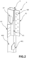
- connection system also includes an assembly fitting system 6 fixed, preferably welded, to the peripheral wall of the upright 4.
- the assembly fitting system 6 comprises a first assembly wing 61, for assembly by riveting with the assembly wing 5314 of the beam 31 of the ceiling frame 3; and a second assembly wing 62, for assembly by riveting with the assembly wing 5324 of the crosspiece 32 of the ceiling frame 3.
- the assembly fitting system 6 comprises a wing 61 which extends orthogonally to a face 461 of the upright, and a wing 62 which extends orthogonally to a face 462 of the upright, adjacent to the face 461.
- Each wing is thus extends in a vertical plane, orthogonal to the face of the upright to which it is fixed, preferably at a distance from the planes of the faces of the upright which are close to the fixing face.
- each wing 61, 62 extends along a median longitudinal axis of the face 461, 462 to which said wing is fixed.
- the fitting system 6 comprises a connecting part 63 which connects the two wings 61, 62.
- the two wings 61, 62 extend orthogonally relative to each other.
- the assembly fitting system 6 is made in one piece by cutting and folding a sheet metal blank.
- the wings 61, 62 it is possible for the wings 61, 62 to be formed from two separate pieces welded to the upright 4.
- the wing 62 extends below the opening 47 made in the face 462 of the upright to which it is fixed, said opening 47 being intended to collect water from a channel of the construction.
- the other wing 61 has a passage orifice 68 for a hooking member 8.
- Each of the wings 61 and 62 extends parallel to the longitudinal axis of the upright, orthogonal to the face of the upright 4 to which it is fixed. When the construction is on a horizontal floor, each upright is then vertical and the wings 61, 62 also extend vertically and from the upright towards a crosspiece or a beam of the ceiling frame.
- an assembly fitting system which may be identical to the assembly system 6, is fixed in the lower part of the upright.
- the terms high, or upper, and low, or lower are defined with reference to a positioning of the construction on a horizontal ground, the amounts then being vertical.
- the assembly fitting system in the lower part of the upright has a wing parallel to the wing 61, and another wing parallel to the wing 62 of the upper assembly fitting system.
- the through hole 68 is located opposite the through hole 58 of the corresponding assembly wing 5314 of the fitting system d assembly 5 for the passage of a hooking member 8 through said orifices 58, 68.
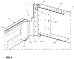
- the assembly wing 5314 of the assembly fitting system 5, through which the through orifice 58 is provided, is spaced from the interior vertical face of the spar 31 to which said assembly wing 5314 is fixed, to leave a reservation between the upright 4 and said spar 31, for the insertion of the hooking member 8 into the facing orifices 58, 68.
- the interior vertical face of the spar 31 is the face of the spar which faces the other spar of the chassis.
- the spar has an exterior vertical (or lateral) face, parallel to the interior vertical (or lateral) face, but whose normal is oriented towards the exterior of the chassis, and upper and lower (horizontal) faces.
- the spacing distance D5 between the assembly wing 5314 of the first assembly fitting system 5 and the interior vertical face is illustrated in the Figure 3 and to the Figure 4 .
- the assembly wing 61 of the fitting system 6 is assembled by riveting with the assembly wing 5314 of the fitting system 5.
- the assembly wing 62 of the fitting system 6 is assembled by riveting with the assembly wing 5324 of the crosspiece 32.
- the facing of the orifices 58, 68 allows the passage of the hooking member 8 through said orifices.
- the hooking member 8 can be a hook as in the example illustrated in Figure 3 .
- the hooking member may be another member, such as a link capable of receiving a hook.
- the spacing of the wing 5314 relative to the interior vertical face of the spar 31 leaves a space which forms a reservation allowing the hooking member 8 to pass freely through the orifices 58, 68, without being hindered by construction elements.
- the orifices 58, 68 are located at a height which remains lower than the upper end of the upright, which makes it possible to limit the bulk and the number of parts necessary for lifting in comparison with the solutions known from the state of the art which require adding a dedicated lifting piece above the upright.
- the through holes used for the passage of the hooking member are made in the assembly wing fixed to the crosspiece of the ceiling frame and in the corresponding wing fixed to the upright and assembled by riveting to said assembly wing fixed to the crosspiece.
- the lifting function is thus obtained by a space reserved on the parts ensuring the mechanical connection in which a cutout, preferably circular, is made to produce said through holes 58, 68.
- This design makes it possible to distribute the forces to be transmitted during lifting between the wings of the two fitting systems 5, 6.
- the wings fixed to the ceiling frame take up the forces due to the own weight of the ceiling (roof) and the wings of the upright take up the forces. forces due to the weight of the posts and the floor.
- the method is described for fixing a fitting system 6 to an upright 4 (in the upper part of the upright) with a view to assembling the fitting system 6 by riveting with a fitting system 5 fixed to a spar 31 and to a crosspiece 32 of the ceiling frame.
- the beam 31 is a crosspiece and the beam 32 a spar.
- the method also applies to the fixing of an additional 6' fitting system, in the lower part of the upright, with a view to assembling by riveting the additional 6' fitting system (in the lower part of the upright) with another 5' fitting system attached to a spar and a cross member of the floor frame.
- the fitting systems used in the lower part of the upright may be identical or similar to those used in the upper part. It should be noted that the fitting systems for the connection in the lower part of the upright with the floor frame may or may not have holes for the passage of a hooking member. It can be planned that the fitting systems used at the top and bottom are identical (therefore with facing holes in at least two wings of the fitting systems) to limit the number of different parts to be used.
- the method thus comprises the following steps for each amount.
- the terms high, or upper, and low, or lower are defined with reference to a positioning of the construction on a horizontal ground, the amounts then being vertical.
- the assembly fitting system 6 is welded to the upright in the upper part of the upright.
- the two wings 61, 62 extend orthogonally relative to each other and parallel to the longitudinal axis of the upright.
- the wing 62 is below the opening 47 intended to collect water from a construction channel.
- the other wing 61 has the passage orifice 68 for the attachment member.
- an assembly fitting system 6' which may be identical to the assembly system 6, is fixed in the lower part of the upright.
- the assembly fitting system has a wing parallel to the wing 61, and another wing parallel to the wing 62.
- the entire upright and fitting systems can then be galvanized.
- the entire upright and the fitting systems which are welded to it (before assembly by riveting with the other fitting systems fixed to the frames), preferably by welding, retain a limited size which allows it to be easily transported and galvanized.
- the corrosion resistance of the assembly is also high due to the fact that the weld beads applied to the fitting systems are protected by the zinc of the hot-dip galvanizing.
- the wings of the fitting systems pre-welded to the post which are intended to be riveted to the corresponding wings of the fitting systems of the floor and ceiling frames make it possible to avoid having to carry out welding at the assembly site (yet called 3D rendering) of the construction module during the assembly of the uprights with the floor and ceiling frames.
- assembly site yet called 3D rendering
- the assembly When put into 3D, the assembly by seamless riveting of the wooden frames, fitted with fitting systems fixed to the beams of the frames, with metal uprights fitted with pre-welded fitting systems, also makes it possible to pre-equip parts of the frames. construction such as ceiling and floor frames, before the assembly corresponding to the 3D setting, without risk of damage to said equipment which could occur (during the 3D setting) if the assembly was carried out by welding, due to possible projections.
- An assembly wing 5314 of the fitting system 5 is fixed to a spar 31 of the ceiling frame by a fixing part 5310 which is inserted into a slot provided in one end of the spar 31, preferably in the vertical median plane of the spar 31.
- the fixing part 5310 is in the form of a plate which extends vertically inside the spar and which is extended by the assembly wing 5314 which extends projecting from the end of the spar.
- the entire assembly wing 5314 and the fixing part 5310 extend along the longitudinal axis of the spar 31.
- a space remains free between the assembly wing 5314 and the plane of the interior lateral (vertical) face of the spar to which the assembly wing 5314 is fixed by the fixing part 5310.
- the assembly wing 5324 is fixed to the crosspiece 32 of the ceiling frame by a fixing part 5320 which is inserted into a slot provided in one end of the crosspiece 32, preferably in the vertical midplane of the crossing.
- the fixing part 5320 is in the form of a plate which extends vertically inside the crosspiece and which is extended by the assembly wing 5324 which extends projecting from the end of the crosspiece 32.
- the entire assembly wing 5324 and the fixing part 5320 extend along the longitudinal axis of the crosspiece 32.
- Fastening elements such as pins or screws, are pressed into the corresponding beams (spar and crossmember) of the chassis to fix each fixing part 5310, 5320 engaged in a spar slot 31 or crossmember 32.
- the fixing elements are 'extend transversely to the spar or to the crosspiece and pass through said fixing part 5310, 5320.
- Orifices can be preformed in the fixing part 5310, 5320 for the passage of the fixing elements or can be formed by the fixing elements themselves even during their installation (for example with self-drilling screws).
- the wings 5314, 5324, and the fixing parts 5310, 5320 are made of metal, preferably steel, as are the wings 61, 62 to which the wings 5314, 5324 are riveted.
- the wings 5314, 5324 are positioned opposite the wings 61 respectively 62 of the upright.
- the wing 5314 is then riveted with the wing 61, and the wing 5324 is riveted with the wing 62.
- Several rivets are used to ensure proper attachment of the wings to each other.
- the connecting part 533 is superimposed on the connecting part 63.
- the wing 5314 is in particular positioned against the wing 61 so as to position the orifices 58, 68 facing each other to allow the passage of the hooking member 8 through all of the two orifices 58, 68.
- the assembly wings 61, 62 and 5314, 5324 do not exceed the upper end of the upright 4.
- the orifices 58, 68 usable for the passage of a hooking member 8 remain included in the overall dimensions (volume) of the construction delimited by the uprights and ceiling and floor frames.
- the size of the construction thus remains limited and the fact of providing orifices for the passage of a hooking member in connecting fittings between the upright and beams (preferably the longitudinal members) of the chassis ceiling, avoids having to add a dedicated part to the upper end of the upright.
- the connecting fitting formed by the assembly of the fixing part 5310 and the wing 5314, and that the connecting fitting formed by the assembly of the fixing part 5320 and the wing 5324, extend along the longitudinal axis of the spar 31, respectively of the crosspiece 32, and in particular extend in the vertical mean plane of said spar or of said crosspiece, allows good distribution of forces during lifting, and a limitation of parasitic moments.
- the assembly by riveting of the wings of the lower part of the upright with the corresponding wings of a spar and a crosspiece of the floor frame can be carried out as described above for the wings of the upper part of the upright with the corresponding wings of a spar and a crosspiece of the ceiling frame.
- the construction can be lifted by hanging sling hooks (connected to a crane) either directly through the holes 58, 68 provided in the assembly wings between each upright and a longitudinal member of the ceiling frame, or to elements of hooking 8, such as rings, which extend through said orifices 58, 68.
- the presence of the metal posts 4 as uprights, and the arrangement of the connecting fittings between posts and beams of the frames in the beam axis, make it possible to ensure good rigidity of the construction and good resumption of efforts, which avoids having to use a spreader bar.
Landscapes
- Engineering & Computer Science (AREA)
- Architecture (AREA)
- Physics & Mathematics (AREA)
- Electromagnetism (AREA)
- Civil Engineering (AREA)
- Structural Engineering (AREA)
- Joining Of Building Structures In Genera (AREA)
Applications Claiming Priority (1)
| Application Number | Priority Date | Filing Date | Title |
|---|---|---|---|
| FR2210102A FR3140386B1 (fr) | 2022-10-03 | 2022-10-03 | Construction, de préférence modulaire, comprenant un châssis de plafond en bois et un châssis de plancher en bois |
Publications (2)
| Publication Number | Publication Date |
|---|---|
| EP4350095A1 true EP4350095A1 (de) | 2024-04-10 |
| EP4350095B1 EP4350095B1 (de) | 2024-11-06 |
Family
ID=84331490
Family Applications (1)
| Application Number | Title | Priority Date | Filing Date |
|---|---|---|---|
| EP23200148.7A Active EP4350095B1 (de) | 2022-10-03 | 2023-09-27 | Konstruktion, vorzugsweise modulares, mit einem holzdeckenrahmen und einem holzbodenrahmen |
Country Status (3)
| Country | Link |
|---|---|
| EP (1) | EP4350095B1 (de) |
| ES (1) | ES3007994T3 (de) |
| FR (1) | FR3140386B1 (de) |
Cited By (1)
| Publication number | Priority date | Publication date | Assignee | Title |
|---|---|---|---|---|
| EP4628667A1 (de) * | 2024-04-03 | 2025-10-08 | Cougnaud | Konstruktion, vorzugsweise modulares, mit einem holzdeckenrahmen und einem holzbodenrahmen |
Families Citing this family (1)
| Publication number | Priority date | Publication date | Assignee | Title |
|---|---|---|---|---|
| CN118979564B (zh) * | 2024-10-22 | 2025-02-07 | 山东佳邦机械设备有限公司 | 一种模块化建筑连接节点及连接方法 |
Citations (2)
| Publication number | Priority date | Publication date | Assignee | Title |
|---|---|---|---|---|
| FR2951213A1 (fr) * | 2009-10-09 | 2011-04-15 | Exaitec | Structure de construction modulaire parallelepipedique munie de moyens de prise en charge par le dessus |
| WO2012129601A1 (en) * | 2011-03-30 | 2012-10-04 | Blue Arc International Pty Ltd | Building system |
-
2022
- 2022-10-03 FR FR2210102A patent/FR3140386B1/fr active Active
-
2023
- 2023-09-27 ES ES23200148T patent/ES3007994T3/es active Active
- 2023-09-27 EP EP23200148.7A patent/EP4350095B1/de active Active
Patent Citations (2)
| Publication number | Priority date | Publication date | Assignee | Title |
|---|---|---|---|---|
| FR2951213A1 (fr) * | 2009-10-09 | 2011-04-15 | Exaitec | Structure de construction modulaire parallelepipedique munie de moyens de prise en charge par le dessus |
| WO2012129601A1 (en) * | 2011-03-30 | 2012-10-04 | Blue Arc International Pty Ltd | Building system |
Cited By (2)
| Publication number | Priority date | Publication date | Assignee | Title |
|---|---|---|---|---|
| EP4628667A1 (de) * | 2024-04-03 | 2025-10-08 | Cougnaud | Konstruktion, vorzugsweise modulares, mit einem holzdeckenrahmen und einem holzbodenrahmen |
| FR3160987A1 (fr) * | 2024-04-03 | 2025-10-10 | Cougnaud | Construction, de préférence modulaire, comprenant un châssis de plafond en bois et un châssis de plancher en bois |
Also Published As
| Publication number | Publication date |
|---|---|
| ES3007994T3 (en) | 2025-03-21 |
| FR3140386B1 (fr) | 2024-09-06 |
| FR3140386A1 (fr) | 2024-04-05 |
| EP4350095B1 (de) | 2024-11-06 |
Similar Documents
| Publication | Publication Date | Title |
|---|---|---|
| EP4350095B1 (de) | Konstruktion, vorzugsweise modulares, mit einem holzdeckenrahmen und einem holzbodenrahmen | |
| EP2347057B1 (de) | Modulares konstruktionssystem | |
| EP2674538B1 (de) | Modulkonstruktion und entsprechendes Verfahren zum Zusammenbau | |
| BE1011185A5 (fr) | Ossature de batiment. | |
| EP2767499B1 (de) | Laschenverbindungsvorrichtung zur Verbindung von zwei Mastelementen, und Anordnung, die zwei Mastelemente und solche Laschenverbindungsvorrichtungen umfasst | |
| FR3005669A1 (fr) | Panneau de construction bois-beton | |
| EP0864702B1 (de) | Traggerüst für Gebäude hergestellt von kaltgewalzten Profilen | |
| WO2021099593A1 (fr) | Module d'habitation préfabriqué | |
| FR2914117A1 (fr) | Montant ouvert renforce pour armoire electrique | |
| EP4628667A1 (de) | Konstruktion, vorzugsweise modulares, mit einem holzdeckenrahmen und einem holzbodenrahmen | |
| FR3033584B1 (fr) | Construction modulaire a partir d'elements prefabriques | |
| FR2689555A1 (fr) | Ensemble de fixation sur le sol d'éléments de structure d'une enceinte démontable. | |
| FR3025503A1 (fr) | Ensemble de construction pour pylone d’ascenseur et pylone d’ascenseur associe | |
| FR2952663A1 (fr) | Profiles de maintien mecanique et recouvrement des modules | |
| WO2021099591A1 (fr) | Procédé de construction d'un bâtiment et systèmes pour sa mise en oeuvre | |
| EP3619379B1 (de) | Satz von strukturelementen zur bildung eines mehrgeschossigen, oberirdischen parkhauses und entsprechendes mehrgeschossiges oberirdisches parkhaus | |
| BE1015141A3 (fr) | Ossature de batiment. | |
| FR3057289B1 (fr) | Element de construction pour poutre mixe acier-beton arme, ensemble de construction et kits de construction | |
| EP0826840A1 (de) | Bauzelle | |
| EP2549025B1 (de) | Baumodul eines Gebäudes | |
| BE1028180B1 (fr) | Structure habitable préfabriquée et transportable | |
| EP1849930B1 (de) | Stützarm für modulares Gerüstsystem sowie modulares Gerüstsystem mit einem solchen Stützarm | |
| EP2871298A1 (de) | Modulsystem zum Bau von Gebäuden, das mit Platinen befestigte Module umfasst | |
| FR3155847A1 (fr) | Pergola comprenant un système d’assemblage et procédé de montage associé | |
| FR2991696A1 (fr) | Ossature de plancher pour construction de preference modulaire |
Legal Events
| Date | Code | Title | Description |
|---|---|---|---|
| PUAI | Public reference made under article 153(3) epc to a published international application that has entered the european phase |
Free format text: ORIGINAL CODE: 0009012 |
|
| STAA | Information on the status of an ep patent application or granted ep patent |
Free format text: STATUS: THE APPLICATION HAS BEEN PUBLISHED |
|
| AK | Designated contracting states |
Kind code of ref document: A1 Designated state(s): AL AT BE BG CH CY CZ DE DK EE ES FI FR GB GR HR HU IE IS IT LI LT LU LV MC ME MK MT NL NO PL PT RO RS SE SI SK SM TR |
|
| STAA | Information on the status of an ep patent application or granted ep patent |
Free format text: STATUS: REQUEST FOR EXAMINATION WAS MADE |
|
| 17P | Request for examination filed |
Effective date: 20240516 |
|
| RBV | Designated contracting states (corrected) |
Designated state(s): AL AT BE BG CH CY CZ DE DK EE ES FI FR GB GR HR HU IE IS IT LI LT LU LV MC ME MK MT NL NO PL PT RO RS SE SI SK SM TR |
|
| GRAP | Despatch of communication of intention to grant a patent |
Free format text: ORIGINAL CODE: EPIDOSNIGR1 |
|
| STAA | Information on the status of an ep patent application or granted ep patent |
Free format text: STATUS: GRANT OF PATENT IS INTENDED |
|
| RIN1 | Information on inventor provided before grant (corrected) |
Inventor name: DEFURNE, CHRISTOPHE Inventor name: SUAUDEAU, ERIC Inventor name: TAHA, HABIB Inventor name: GUERIN, ALEXANDRE |
|
| RIC1 | Information provided on ipc code assigned before grant |
Ipc: E04B 1/24 20060101ALN20240610BHEP Ipc: E04B 1/26 20060101ALI20240610BHEP Ipc: E04B 1/348 20060101AFI20240610BHEP |
|
| INTG | Intention to grant announced |
Effective date: 20240626 |
|
| GRAS | Grant fee paid |
Free format text: ORIGINAL CODE: EPIDOSNIGR3 |
|
| GRAA | (expected) grant |
Free format text: ORIGINAL CODE: 0009210 |
|
| STAA | Information on the status of an ep patent application or granted ep patent |
Free format text: STATUS: THE PATENT HAS BEEN GRANTED |
|
| AK | Designated contracting states |
Kind code of ref document: B1 Designated state(s): AL AT BE BG CH CY CZ DE DK EE ES FI FR GB GR HR HU IE IS IT LI LT LU LV MC ME MK MT NL NO PL PT RO RS SE SI SK SM TR |
|
| REG | Reference to a national code |
Ref country code: GB Ref legal event code: FG4D Free format text: NOT ENGLISH |
|
| REG | Reference to a national code |
Ref country code: CH Ref legal event code: EP |
|
| REG | Reference to a national code |
Ref country code: DE Ref legal event code: R096 Ref document number: 602023000942 Country of ref document: DE |
|
| REG | Reference to a national code |
Ref country code: IE Ref legal event code: FG4D Free format text: LANGUAGE OF EP DOCUMENT: FRENCH |
|
| REG | Reference to a national code |
Ref country code: LT Ref legal event code: MG9D |
|
| REG | Reference to a national code |
Ref country code: NL Ref legal event code: MP Effective date: 20241106 |
|
| REG | Reference to a national code |
Ref country code: ES Ref legal event code: FG2A Ref document number: 3007994 Country of ref document: ES Kind code of ref document: T3 Effective date: 20250321 |
|
| PG25 | Lapsed in a contracting state [announced via postgrant information from national office to epo] |
Ref country code: IS Free format text: LAPSE BECAUSE OF FAILURE TO SUBMIT A TRANSLATION OF THE DESCRIPTION OR TO PAY THE FEE WITHIN THE PRESCRIBED TIME-LIMIT Effective date: 20250306 Ref country code: PT Free format text: LAPSE BECAUSE OF FAILURE TO SUBMIT A TRANSLATION OF THE DESCRIPTION OR TO PAY THE FEE WITHIN THE PRESCRIBED TIME-LIMIT Effective date: 20250306 Ref country code: HR Free format text: LAPSE BECAUSE OF FAILURE TO SUBMIT A TRANSLATION OF THE DESCRIPTION OR TO PAY THE FEE WITHIN THE PRESCRIBED TIME-LIMIT Effective date: 20241106 |
|
| PG25 | Lapsed in a contracting state [announced via postgrant information from national office to epo] |
Ref country code: NL Free format text: LAPSE BECAUSE OF FAILURE TO SUBMIT A TRANSLATION OF THE DESCRIPTION OR TO PAY THE FEE WITHIN THE PRESCRIBED TIME-LIMIT Effective date: 20241106 Ref country code: FI Free format text: LAPSE BECAUSE OF FAILURE TO SUBMIT A TRANSLATION OF THE DESCRIPTION OR TO PAY THE FEE WITHIN THE PRESCRIBED TIME-LIMIT Effective date: 20241106 |
|
| REG | Reference to a national code |
Ref country code: AT Ref legal event code: MK05 Ref document number: 1739491 Country of ref document: AT Kind code of ref document: T Effective date: 20241106 |
|
| PG25 | Lapsed in a contracting state [announced via postgrant information from national office to epo] |
Ref country code: BG Free format text: LAPSE BECAUSE OF FAILURE TO SUBMIT A TRANSLATION OF THE DESCRIPTION OR TO PAY THE FEE WITHIN THE PRESCRIBED TIME-LIMIT Effective date: 20241106 |
|
| PG25 | Lapsed in a contracting state [announced via postgrant information from national office to epo] |
Ref country code: NO Free format text: LAPSE BECAUSE OF FAILURE TO SUBMIT A TRANSLATION OF THE DESCRIPTION OR TO PAY THE FEE WITHIN THE PRESCRIBED TIME-LIMIT Effective date: 20250206 |
|
| PG25 | Lapsed in a contracting state [announced via postgrant information from national office to epo] |
Ref country code: GR Free format text: LAPSE BECAUSE OF FAILURE TO SUBMIT A TRANSLATION OF THE DESCRIPTION OR TO PAY THE FEE WITHIN THE PRESCRIBED TIME-LIMIT Effective date: 20250207 Ref country code: LV Free format text: LAPSE BECAUSE OF FAILURE TO SUBMIT A TRANSLATION OF THE DESCRIPTION OR TO PAY THE FEE WITHIN THE PRESCRIBED TIME-LIMIT Effective date: 20241106 Ref country code: AT Free format text: LAPSE BECAUSE OF FAILURE TO SUBMIT A TRANSLATION OF THE DESCRIPTION OR TO PAY THE FEE WITHIN THE PRESCRIBED TIME-LIMIT Effective date: 20241106 |
|
| PG25 | Lapsed in a contracting state [announced via postgrant information from national office to epo] |
Ref country code: PL Free format text: LAPSE BECAUSE OF FAILURE TO SUBMIT A TRANSLATION OF THE DESCRIPTION OR TO PAY THE FEE WITHIN THE PRESCRIBED TIME-LIMIT Effective date: 20241106 |
|
| PG25 | Lapsed in a contracting state [announced via postgrant information from national office to epo] |
Ref country code: RS Free format text: LAPSE BECAUSE OF FAILURE TO SUBMIT A TRANSLATION OF THE DESCRIPTION OR TO PAY THE FEE WITHIN THE PRESCRIBED TIME-LIMIT Effective date: 20250206 |
|
| PG25 | Lapsed in a contracting state [announced via postgrant information from national office to epo] |
Ref country code: SM Free format text: LAPSE BECAUSE OF FAILURE TO SUBMIT A TRANSLATION OF THE DESCRIPTION OR TO PAY THE FEE WITHIN THE PRESCRIBED TIME-LIMIT Effective date: 20241106 |
|
| PG25 | Lapsed in a contracting state [announced via postgrant information from national office to epo] |
Ref country code: DK Free format text: LAPSE BECAUSE OF FAILURE TO SUBMIT A TRANSLATION OF THE DESCRIPTION OR TO PAY THE FEE WITHIN THE PRESCRIBED TIME-LIMIT Effective date: 20241106 |
|
| PG25 | Lapsed in a contracting state [announced via postgrant information from national office to epo] |
Ref country code: EE Free format text: LAPSE BECAUSE OF FAILURE TO SUBMIT A TRANSLATION OF THE DESCRIPTION OR TO PAY THE FEE WITHIN THE PRESCRIBED TIME-LIMIT Effective date: 20241106 |
|
| PG25 | Lapsed in a contracting state [announced via postgrant information from national office to epo] |
Ref country code: RO Free format text: LAPSE BECAUSE OF FAILURE TO SUBMIT A TRANSLATION OF THE DESCRIPTION OR TO PAY THE FEE WITHIN THE PRESCRIBED TIME-LIMIT Effective date: 20241106 |
|
| PG25 | Lapsed in a contracting state [announced via postgrant information from national office to epo] |
Ref country code: SK Free format text: LAPSE BECAUSE OF FAILURE TO SUBMIT A TRANSLATION OF THE DESCRIPTION OR TO PAY THE FEE WITHIN THE PRESCRIBED TIME-LIMIT Effective date: 20241106 |
|
| PG25 | Lapsed in a contracting state [announced via postgrant information from national office to epo] |
Ref country code: CZ Free format text: LAPSE BECAUSE OF FAILURE TO SUBMIT A TRANSLATION OF THE DESCRIPTION OR TO PAY THE FEE WITHIN THE PRESCRIBED TIME-LIMIT Effective date: 20241106 |
|
| REG | Reference to a national code |
Ref country code: DE Ref legal event code: R097 Ref document number: 602023000942 Country of ref document: DE |
|
| PG25 | Lapsed in a contracting state [announced via postgrant information from national office to epo] |
Ref country code: SE Free format text: LAPSE BECAUSE OF FAILURE TO SUBMIT A TRANSLATION OF THE DESCRIPTION OR TO PAY THE FEE WITHIN THE PRESCRIBED TIME-LIMIT Effective date: 20241106 |
|
| PLBE | No opposition filed within time limit |
Free format text: ORIGINAL CODE: 0009261 |
|
| STAA | Information on the status of an ep patent application or granted ep patent |
Free format text: STATUS: NO OPPOSITION FILED WITHIN TIME LIMIT |
|
| PGFP | Annual fee paid to national office [announced via postgrant information from national office to epo] |
Ref country code: MC Payment date: 20250923 Year of fee payment: 3 |
|
| 26N | No opposition filed |
Effective date: 20250807 |
|
| PGFP | Annual fee paid to national office [announced via postgrant information from national office to epo] |
Ref country code: LU Payment date: 20250930 Year of fee payment: 3 |
|
| PGFP | Annual fee paid to national office [announced via postgrant information from national office to epo] |
Ref country code: BE Payment date: 20250929 Year of fee payment: 3 |
|
| PGFP | Annual fee paid to national office [announced via postgrant information from national office to epo] |
Ref country code: FR Payment date: 20250929 Year of fee payment: 3 |
|
| PGFP | Annual fee paid to national office [announced via postgrant information from national office to epo] |
Ref country code: DE Payment date: 20250929 Year of fee payment: 3 |
|
| PGFP | Annual fee paid to national office [announced via postgrant information from national office to epo] |
Ref country code: IT Payment date: 20250930 Year of fee payment: 3 |
|
| P01 | Opt-out of the competence of the unified patent court (upc) registered |
Free format text: CASE NUMBER: UPC_APP_0017291_4350095/2025 Effective date: 20251212 |
|
| PGFP | Annual fee paid to national office [announced via postgrant information from national office to epo] |
Ref country code: ES Payment date: 20251030 Year of fee payment: 3 |